
Just a 8000-8100 rpm limit iincrease
Redline increase and sport mode always on
Slight power bump (stockish car) ~10whp
Mid power bump (you have headers, euro or aftermarket) ~30whp
Larger power bump (headers/full exhaust/CSL style intake) ~40+whp
 Lurker
BMW CCA Member
Lurker
BMW CCA Member
Bump for updates.
-Ed Hands
MaxPSI Stg2 Turbo
R.Forbes magic F&R
100K Original owner miles.
Proud member of the BF.c FI - Big Torque Club (>500wtq Dyno Results)
:facepalm
I posted this in the performance and power rankings thread.
~295HP/240tq
This is interim progress. I will be going back for another go. They think there is a good bit more to extract. We only spent about 2 hours and maybe 13-14 dyno pulls.
The sport mode change was made and tested. We have to work up a small circuit to implement it in our cars because the ECU outputs 5v that normally lights up the small green led on the sport button itself and our dash light needs 12v. If anyone wants to help design this, get in touch. I've heard several different options from a simple relay to a power transistor and a few others.
Interim dyno graph.
Scott_dyno.jpg
Member
I have used the stock tune, Shark Injector, and Jailbreak Tuning as well on the S54 Z3.. Would be very interesting to see if this makes a difference!
ONLY BMW Content is +
Moderator
Can you swap the 5v LED with a 12v one, avoiding the circuit?
Terry
Edit: Circuit
Last edited by Terry F.; 07-15-2014 at 09:55 PM.
Stuff. I got stuff.
:facepalm
Humm...not sure if it's possible to take the bulb out of the fixture and replace it with an LED somehow. That's an interesting thought.
Don't think that's the circuit we need!
ONLY BMW Content is +
Moderator
It's only six components.Originally Posted by fmcfad01

Postage stamp-sized pc board if you wanted to really do it right.
Yeah, bulb swap sounds a lot easier. Hope it works.
T
Stuff. I got stuff.
:facepalm
Ah, i plead ignorance then...what's the component in the middle?
We were hoping to get rid of the need for a PC board in order to bring the cost down.
I'll try to find the info on it using the link in the image.
If it's the right way to do it, thanks!
Coupe Cartel Forever!
BMW CCA Member
I was in the middle of moving... so my availability has been minimal at best.
However I am not about 2.5 miles away from the shop and can stop by soon to get my car on the rollers as well.
Hoping for next week sometime right now; but I have to schedule it with everyone involved still.
~Ken~ '99 M coupe THE "original" TT Stage 3 - HTA3586R; 701 whp 672 wtq @ 26.5 psi ; NeverSell - CoupeCartel
ONLY BMW Content is +
Moderator
The component in the middle is the 8-pin IC that does the voltage conversion. There are numerous 5-12v converters. Capacitors and resistors are super-cheap. The IC will be under 10 bucks, maybe way under. I can design your pcb, if you want to go that route. PCBs will run maybe two hundred if you want to do that. Custom pcb.
Here's a complete solution for $1.25 on eBay. This might be the best way to go if you don't replace the LED:
http://www.ebay.com/itm/5v-to-12v-St...item5b02826102
5V LEDs are under a buck if you decide to swap the bulb.
Terry
Stuff. I got stuff.
:facepalm
Thanks for the offer. I'm sure there is a correct solution, I've just forgotten all of my EE homework.
The Sport Mode Controller I'm using now is made on a custom PCB and costs less than $100, so anything more expensive than that is a non starter.
Was really hoping to use something as simple as a relay to pass 12v to the bulb. That may work, I just need help identifying the correct relay that uses sufficiently low current such that the ECU can drive it.
ONLY BMW Content is +
Moderator
Just to clarify, 200 is for a few quick turn boards. Not per board. These are simple pcb boards, a few bucks if in mass production.
Good luck, thanks for the updates
Stuff. I got stuff.
Dave
That is an interesting idea Terry. Do you know what the current requirements are of the circuit and the rated output current of the ECM channel transistor/output? Its been a while, but I don't think you can more than double the output voltage without limiting the output duty cycle and/or increasing the input current. I would be concerned about blowing an output transistor in the ECM. I wouldn't mind playing with this circuit when my schedule allows.
I've purchased several LED's including PWM LEDS from superbrightleds for electronic projects around the house and IMO is a LED would be the more ECM friendly option. The only question with an LED solution is getting the switch open.
Scott how much was the switch?
Last edited by Mach Tuck; 07-16-2014 at 09:29 PM.
01 M S54 Estoril Coupe (Fun)16 Mini Clubman S(Daily)03 325i (Wifes Car)Your never further away from oblivion than a distracted soccer mom in a SUV.
:facepalm
What switch? The asc or dsc button? $70 or less, bought mine used.
My other concern is, we need to send 12v to the light which is already grounded. Do we have to use the ground on this circuit to get 12v? This is why a power transitor or relay solution may work better.
:facepalm
I have a notional circuit for this but needed a competent EE's help to pick exact part numbers and components. I forgot all of my circuit analysis long ago.
Pm if you can lend a hand.
ONLY BMW Content is +
Moderator
Hey Dave,
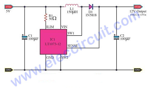
How are things down the block? That circuit I displayed was more of just an example that it is pretty easy to generate the 12V. Whether that circuit/device can provide the current necessary to drive an LED, I don't know. It just came up early on Google Images. I can't see it producing 5W or anything like that, like some LEDs need, I think. There seem to be a lot of 5->12 PMIC like this 1073. There's got to be a solution out there.
Here's a datasheet to the LT1073-12.
http://cds.linear.com/docs/en/datasheet/1073fa.pdf
Terry
Stuff. I got stuff.
:facepalm
The best way to design this would be to completely isolate the DME/ECU from the rest of the circuit.
The idea would be to use an OPAMP (because they isolate and draw 0 current) to drive a P-Channel MOSFET. The DME output is Low (0v) when the light is supposed to be on and High (5v) when the light should be off. The OPAMP has the job of driving the FET at 12v because 5v from the DME would be too low to close the FET. When the signal is low, the FET is open and allows 12v to flow through to the sport mode light.
Thus, the correct OPAMP, MOSFET, and resistor need to be selected. Then a smart way to package this up for use needs to be considered.
OPAMP has 5 pins (V+ Pin 16 from DME, V- Ground, Ground, +12v, and Vout). MOSFET has 3 pins (+12v, input from the OPAMP, and output to the sport light).
Making a small box like the Island controller might be the best. The inputs to the board would only be +12v, GND, Input, and Output.
Dave
Sorry, I missed the reply. The one your going to use for the sport mode.
I agree.
- - - Updated - - -
Doing fine. I've been doing a lot of contract work that's keeping my schedule full.
Interesting. I'll check it out.
- - - Updated - - -
I totally agree.
Yes, this would be a relatively small circuit and the best way IMO, a little more work than replacing a bulb but worth it. A small shrink wrapped hobby board would work and fit behind the panel nicely. I may also use this circuit for an enhancement to my Star Trek pinball machine that I've had on the back burner.
Man, I'd love to play with this but I'm booked solid till the second week of August so I wouldn't be able to put anything together till I got back. I've tried dragging my O-Scope, Soldering Station, etc. around the country once before modifying some PWM Amps for my home automation/lighting systems and it was a total PITA, not to mention some very strange looks from hotel housekeepers!
Let me know what you plan to do. I still owe you for helping me with the sub-frame bushings.
I won't be on the forum regularly for a while so email me with you can.
01 M S54 Estoril Coupe (Fun)16 Mini Clubman S(Daily)03 325i (Wifes Car)Your never further away from oblivion than a distracted soccer mom in a SUV.
:facepalm
Well, remember, you've still got to run wires, make something like the wiring harness I detailed in the sport mode clean install thread, and hide all that stuff around the shifter/under the shift boot. This would basically mean replacing the traditional sport mode controller with this small/cheap circuit. It's really no more work at all than installing sport mode the way we've always had to. I probably wouldn't put it behind the instrument panel.
I'm not really in a rush...my sport mode button works! I do think this is a cool feature of this tune we're working on though. Mid august would be fine if you have the expertise to select the exact components. I guess I can use his name now since it should be obvious from the dyno I posted, but Nick may want to build the circuit and select the components. In the event he's too busy/doesn't care to, I'd love some help and can wait. I'm comfortable soldering and building the thing...it's the selection of components, circuit analysis, and ideal way to put it together/package it that I'd appreciate some help on. My last fundamentals of EE class was sophomore year and probably over 11 years ago.
I don't think you owe me anything after almost killing you that day...On the upside, the M5 is still alive and well and in my garage!
Lurker
BMW CCA Member
I was hoping it was Nick all along, we really are fortunate to have him in the BMW circle. Perhaps he can incorporate some of this into the Max Psi kit.
-Ed Hands
MaxPSI Stg2 Turbo
R.Forbes magic F&R
100K Original owner miles.
Proud member of the BF.c FI - Big Torque Club (>500wtq Dyno Results)
:facepalm
He does the tunes for those kits and Mike at maxPSI said only small changes need to be made to fit one up to our cars. He basically said, if you're ready, I'm ready.
That said, I don't think I'd put one on my car, but if I ever found a high mile s54 at a bargain (non cartel) price, I'd hop on it.
Member
Wow, you're really digging in here.
Personally, I'm much more interested in the real tune than sport mode functionality. Could be because I've had it for years, though I still think it would be nice if I actually turned sport mode ON when driving hard instead of OFF.
-Todd
:facepalm
Lol, yes, part of the tune increases normal mode throttle response and decreases sport mode throttle response (because it's too touchy).
Agree, sport mode is not really the point of this tune, however, I do see it as a feature. If the next session improves the numbers and curves, that alone would attract interest. If sport mode comes along with the tune, i see it as a perk to choosing this over others that people consider similar.
Member
Holy Hell. Ok, looks like I need to get back in the game and pick up an S54 M coupe! Was waiting for something like this. THANK YOU Scott and Z3Speed for your efforts with this.
Member
Realistically, how much of an increase will you see with a canned tune?
I'm interested in a tune for a more linear throttle response. I'm not planning on changing much engine-wise to the car, so I don't need a tune for an aftermarket intake or exhaust, although I will have to install headers and code out the cat inefficiency codes thrown out by aftermarket cats- that will need aftermarket software tuning.
:facepalm
We shall see. Ken and I are working together using both our cars, so the tune I started a few weeks ago will be canned for Ken next week and the end result will be canned for me after Ken continues the effort.
The next step is to get someone with a stock car to volunteer to help develop a tune for cars without euro headers.
We will report back and be fully transparent. Ken and I aren't making any money off this, so if it turns out there aren't gains for stock cars on a canned tune, we'll let it be known and post the dyno to prove it.
Like you said, drivability is a benefit of a tune along with better power. We're hoping to get both.
We're working with the right people to make it happen.
 Posting Permissions


 Reply With Quote


Bookmarks