
 Member
Hi all, 1st post on this forum so I've thought of making it a bit substantial. Tackling the E46 known weak subframe issue.
Below you will find my latest project; being the COMPLETE rear subframe reinforcement. In this guide you will find EVERYTHING required to drop the subframe, perform the reinforcements, and bolt everything back including torque values and parts needed. This project is a result of a lot of research (especially on deciding which kits to purchase) and took me from A to Z, 4 days (12h/day work). Feel free to ask me whatever you want.
Since this is a very lengthy guide, I have uploaded it on my GDrive as a DOCX document, which contains embedded lots of TIS guides and the torque values. This also acts as a printable version or if the hosting decides to take the pictures down. I didn't convert to PDF yet/
https://drive.google.com/open?id=1Gi...GAgw4Afj64fA6L
BMW E46 Complete RACP Reinforcement
This project tackles the weak subframe mounts found on all E46 vehicles. The approach is to reinforce the mounts in a holistic way, from both sides. Top side is from inside the car and bottom side from outside the car. Since the subframe is being lowered, it is great opportunity to also reinforce the weak sway bar (antiroll bar) mounts, especially if aftermarket kits are used. Replacement of bushes and of other worn parts can be done but are not covered in this project. It is unnecessary to say that if you find a rotten hose or something broken, it makes sense to replace it.
Reinforcement Kits:
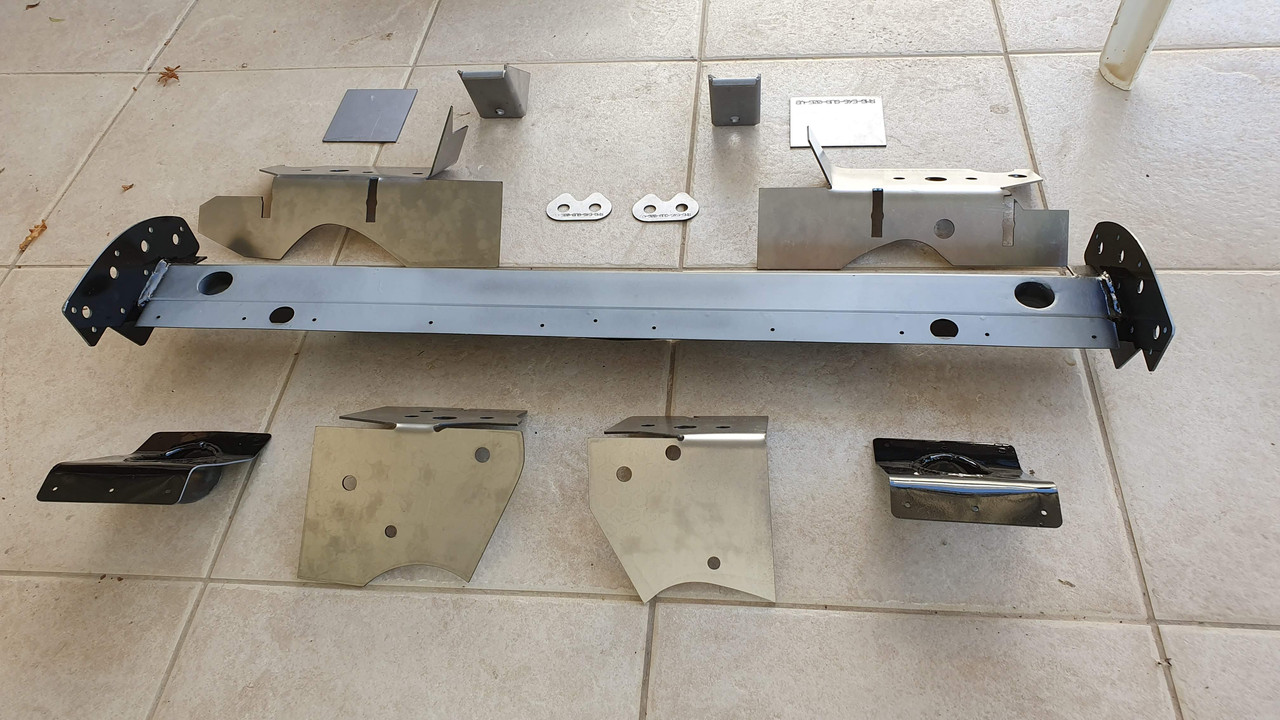
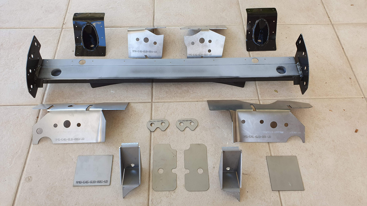
Top Side: PPRND Vincebar v2 Epoxy/Rivet Reinforcement Bar & Gussets.
Bottom Side: Redish Motorsport Weld-On Plates.
Antiroll bar mounts: Garagistic E46 Non-M sway bar kit.
Additional Parts:
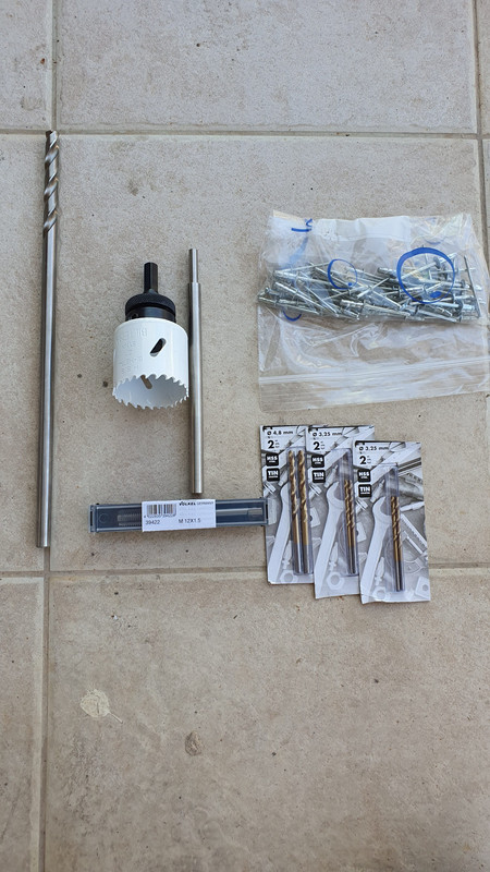
2x 50ml Araldide 2014 Epoxy Gel With dispenser. Link here
1x Vincebar tooling kit (hole saw, drill bits, thread tap, brushes, extended drill)
1L Rust-oleum Anti-rust epoxy paint
Underseal
1x Bitumen undercoating
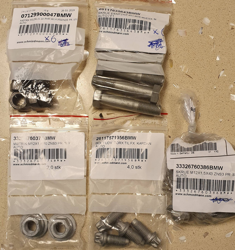
New bolts/nuts/clips of everything that are being removed
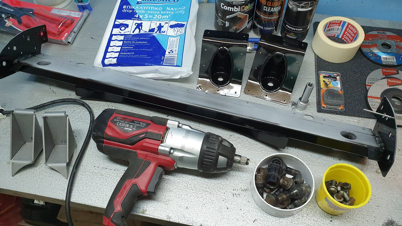
Tools Needed:
1. Angle grinder with thin cutting disks suitable for steel and grinding disks as well
2. Dremel with reinforced disks suitable for steel cutting
3. Heavy duty riveter (Vincebar uses steel rivets)
4. Sandpaper / files / cleaning rugs / brake cleaner / vacuum cleaner / body protection / WD40
5. MIG welder (or someone suitable to weld 2mm steel plates on the E46 body)
6. Powerful drill (as it will need to drive the holesaw through sheet steel)
7. ½ Torque Wrench (20Nm 120Nm range)
8. Impact wrench (helps!)
9. ½ drive wrench
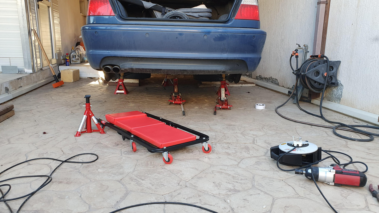
10. Hydraulic jacks, jack stands, mechanics creeper, fire extinguisher
11. Assortment of sockets & spanners, pliers, various sizes from 10mm to 18mm, E12 for driveshaft
12. Rubber mallet, hammer, punches, copper grease, silicone grease, Loctite
13. Eye / Ear / Nose protection, latex gloves, mechanics gloves
Initial Preparation:
Drove the car until no fuel left in tank. Soaked all bolts/nuts overnight with WD40
Parts to be removed:
1. Rear seats and trunk lining
2. Exhaust & heatshield
3. Driveshaft
4. Subframe
5. Fuel tank (for good all-round weld without fire risks)
Consider maintenance on the following:
1. Subframe/differential/trailing arm/control arm bushings
2. Center support bearing
3. Guibo
4. Fuel tank hoses, clips, fuel lines, fuel neck, fuel lid rubber cover
5. Differential output flange seals, diff cover gasket, diff fluid
6. New brake fluid
7. All bolts/nuts (I replaced them with genuine parts)
The top reinforcement is from Practical Performance RnD (PPRND), aka the famous Vincebar. The subframe removal guide and the steps to install the kit are from the online posts from PPRND, which I try to gather and assemble into a more diy-friendly manual. I took many pictures throughout the project but I also used some pictures from Practical Performance RnD to fill some gaps or to provide more elaborations. Of course credit goes to PPRND for giving permission to use the pictures and guides. Obviously if some pictures seem that they are from a different car, its because they are, they are the ones used to provide more detail/fill gaps. The process does not change at all, neither the order of steps.
After discussing with Vincent from PPRND, I decided to get the Epoxy/Rivet kit instead of the weld kit. The arguments were a cleaner install, no metal weakening due to heat, less chances of rust.
The lower reinforcement was purchased from Redish Motorsport. The kit came with printed instructions on what items to remove and where to weld the kit. It is a straightforward job once youve taken everything apart. Please note that I was considering the epoxy kit from Practical Performance at first, but due to availability and my own very tight schedule I went with the weld kit from Redish.***8195;
Part 1 - Main Preparation:
Step 1 Jacking the car
Set the car on stands. I am obsessed with safety. I used 2 jack stands on the rear jack points, cinder blocks on frame, the removed wheels, and 2x hydraulic jacks just preloaded on the frame. Front wheels on ramps and locked with chocks and also another jack preloaded on the front central jack point. Intensively attempt to tilt the car to make sure its steady and secure. I recommend getting it as high in the air as you can.
Step 2 Rear Wheels removal
Remove the rear wheels. Set them under car for safety as mentioned. Set aside 4 wheel bolts as they will be used throughout the project for stabilizing the top bar and bottom plates.
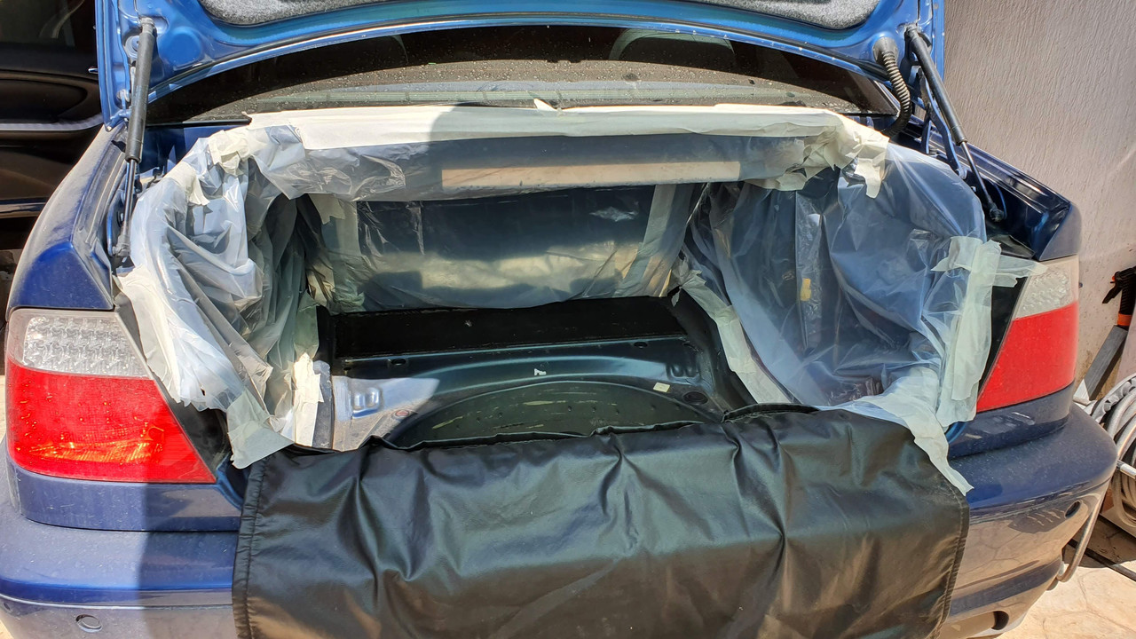
Step 3 Trunk lining and rear seats removal. Trunk lining is secured by plastic clips, I have the folding seats which are only held together by a bracket.
Step 4 Covering stuff. There will be a lot of metal cutting and grinding. Grinded particles are magnetic. Cover as much area as possible, leaving only the place where the actual cutting will happen. I like to put a couple of magnets around my working area, especially near the grinder, it is amazing how much particles they catch.
Subframe Removal:
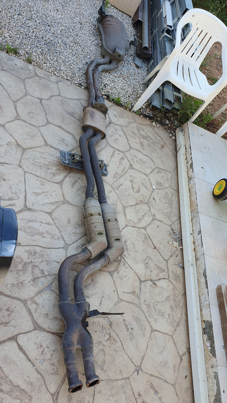
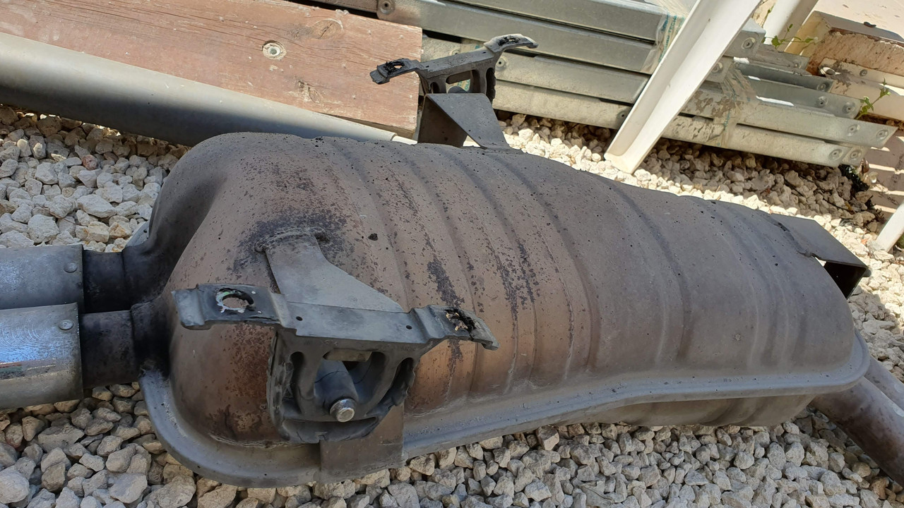
Step 1 Exhaust
Remove the exhaust. There are 4 - 13mm bolts in the rear, 8-13mm bolts on the middle cross members, 2-13mm bolts with rubber spacers that mount to the transmission, and 4-14mm bolts attaching the exhaust to the headers.
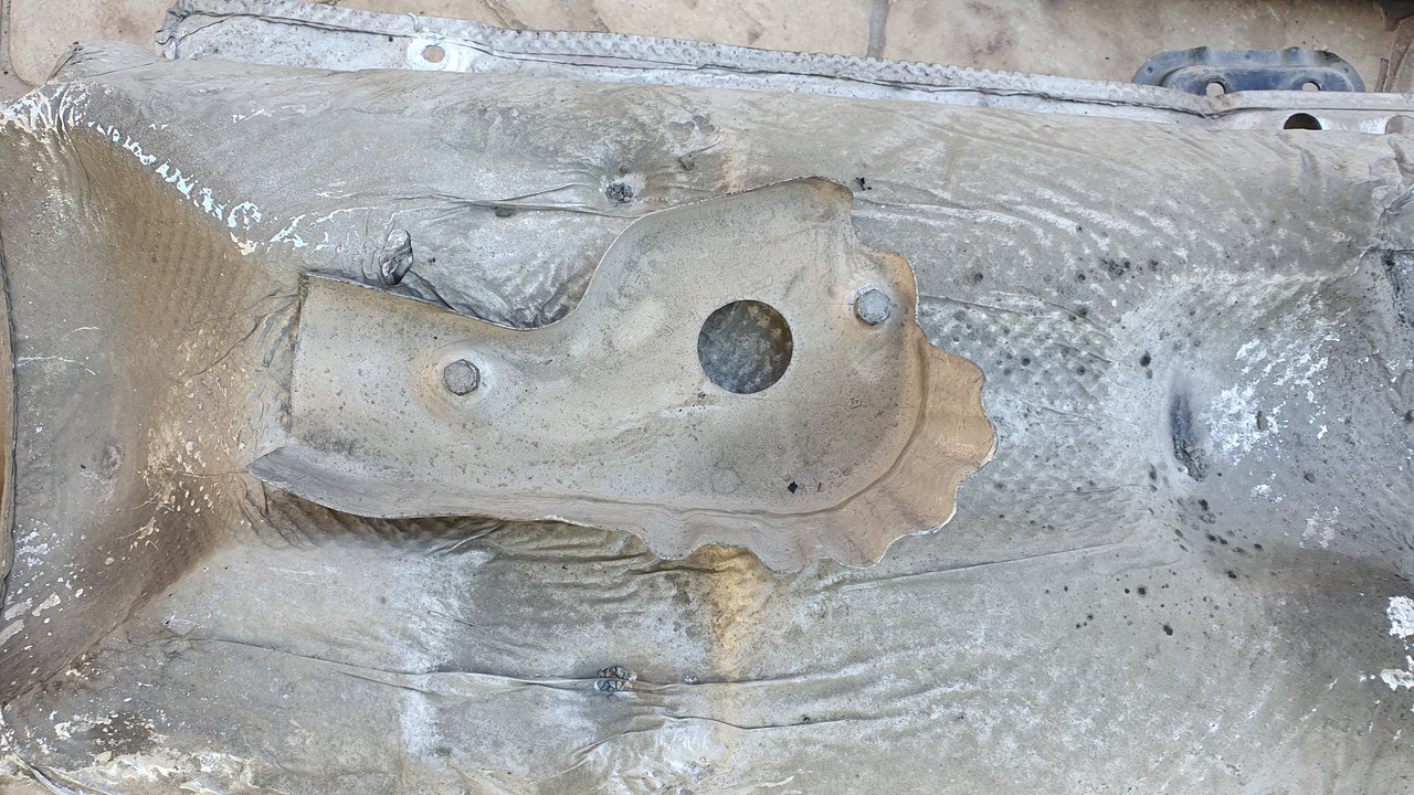
Step 2 Heatshield
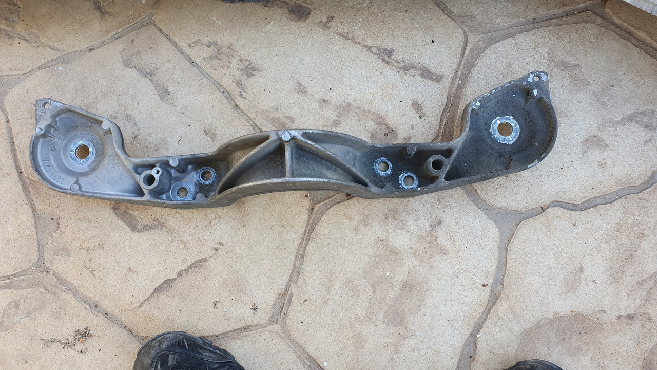
Remove Driveshaft heat shield. 4-10mm bolts, 2 front/2 rear - will need extensions. These screws are probably rusted and beyond reuse.
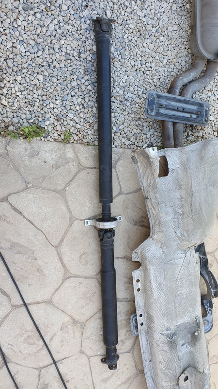
Step 3 - Driveshaft
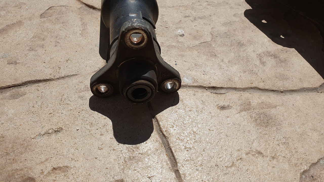
a. Disconnect the driveshaft from guibo. There are 3-18mm nuts/bolts (60 Nm) that will require two wrenches to remove.
b. Disconnect driveshaft center carrier mount. 2-13mm (20 Nm) nuts that attach to chassis.
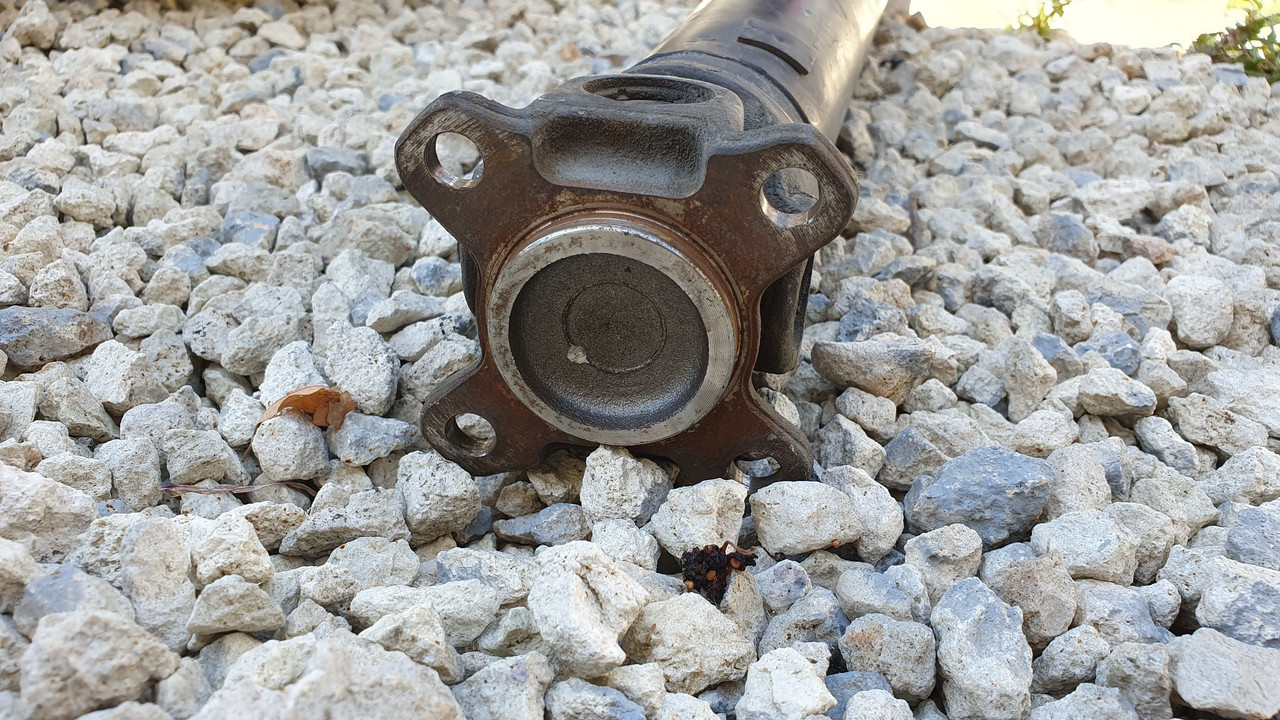
c. Disconnect driveshaft from differential. You will need an E12 torx to remove these bolts. Get whichever ones you can get to. Then, release the e-brake from inside the car, rotate the driveshaft, and re-engage e-brake to get the other bolts. There are 4 total. (82 Nm)
d. Remove small aluminum shield. There are 2-10mm bolts holding it on.
e. Remove the aluminum guard at the end of the driveshaft. It has 4-13mm bolts (30 Nm) and 2-18mm bolts. (77 Nm)
f. Separating the driveshaft from the differential will be difficult. There is a lip (as pictured) securing the driveshaft to the differential.
g. A few taps of a rubber mallet and some elbow grease should do the trick. The driveshaft should now be removed.
Step 4 Shocks
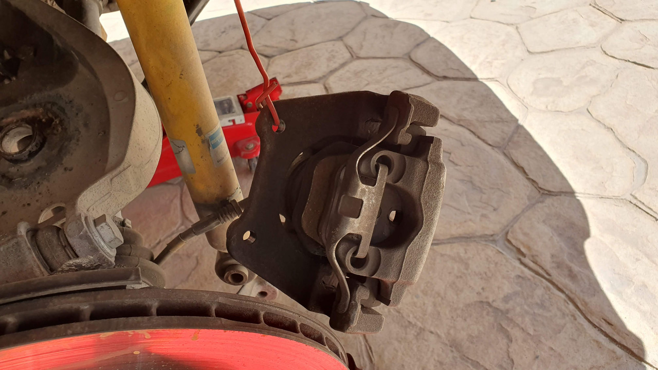
Unbolt shock from the hub on both sides. There is 1-18mm bolt (100 Nm) on each side. Support the hub with a jack before you loosen to prevent the hub being sprung down and damaging the brake lines. Repeat on opposite side.
Step 5 Brake Calipers
Disconnect brake caliper and hang. Disconnect the flex brake line from the steel line using a combination of 14mm (flex side) and 11mm spanner (steel side). Repeat on opposite side. I use a small piece of rubber hose that is blocked to one end, and with a clip I secure it on the steel brake line. This prevents spillage of brake fluid and eventually draining the system. The initial pressure will be inevitably relieved so have some rugs ready and some brake cleaner.
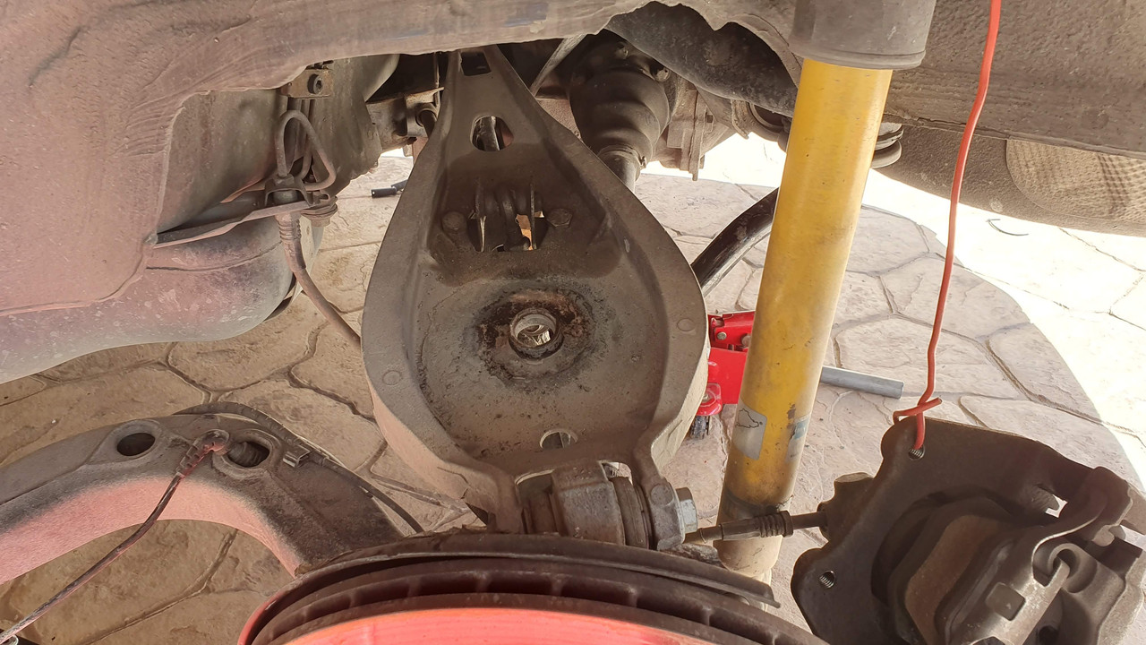
Step 6 Trailing arms
Unbolt rear trailing arm from body. There are 3-18mm bolts (77 Nm) on each side. Make notes on their position. Car will need an alignment at the end, this is just to get it approximately back to where it was. Also take out the springs once the trailing arm is free. To remove the springs, just slide them away.
Step 7 - Electrics
Coming from each brake assembly, there will be one or two wires leading to a black box mounted on each inner fender. Open these boxes and disconnect the wires. These are the brake pad wear sensor and the ASC/ABS. My car had 2 wires on one side and 1 pair on the other side.
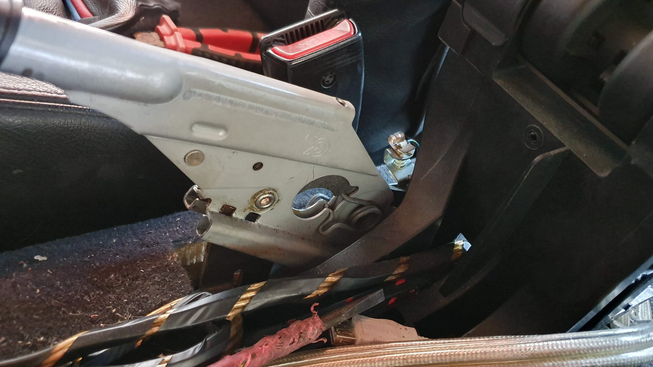
Step 8 Parking Brake
a. From inside the car, remove the parking brake boot. You will see 2-10mm nuts under the lever. Remove these nuts and washers. I used a long tubular socket.
b. From underneath the car, pull on the two parking brake cables you see going into the body. Once pulled through, grip them by the control arm and pull them through the other body piece. I had some difficulty removing the cable as it was catching on the tubes end inside the cabin. So to make things easier, I removed the center console and used my assistant to wiggle the cable a bit while I pulled from below the car.
Step 9 Dropping the subframe
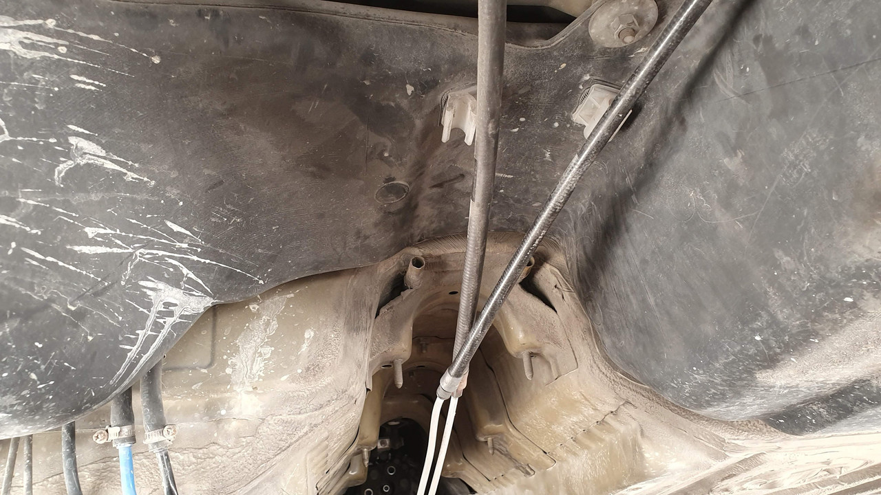
Support the sub frame and everything else left. Remove the 4-18mm bolts (77 Nm) holding the sub frame to the body (the 2 nuts should have already been removed already during the driveshaft removal process). The front mounts may need a little crowbar encouragement to slip loose. Slowly lower the jack and roll the sub frame out from under the car. Do not forget the handbrake lines to be fully out of the car body. The bushes aluminum core easily catches on the threads of the studs so the lowering must be as vertical as possible.
###pic limit####
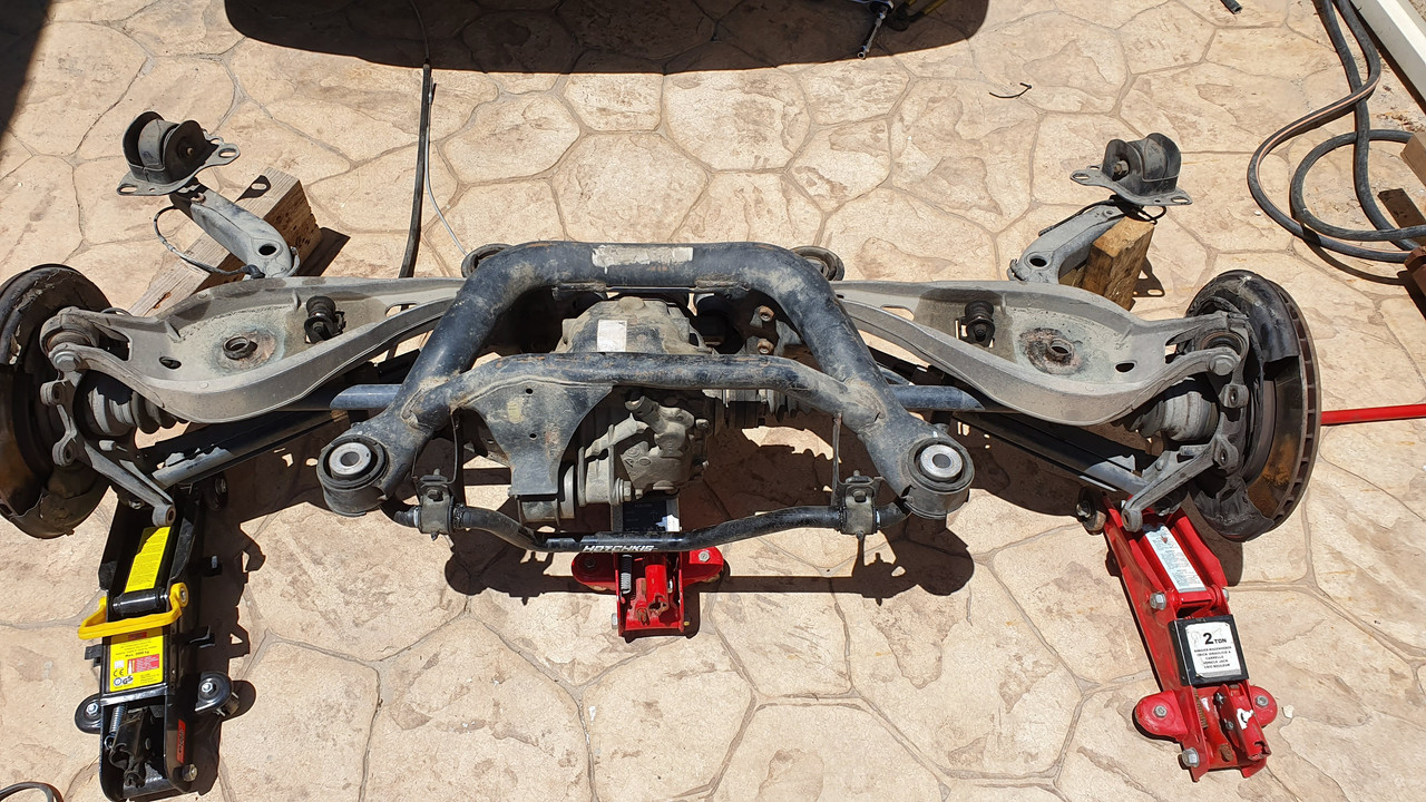
This is the whole subframe with everything still attached on it removed. If you dont have any work planned here, you can leave it aside or completely disassemble it.
Step 11 Fuel tank removal. Good idea to leave as less fuel as possible in the tank. I drove my car until I had about 6L left. This makes it lighter to remove.
a. Disconnect the 2 flex hoses (supply/return) of fuel lines. Discard the clips as new ones are needed.
b. From inside the car, remove the 2 caps located below the rear seat. There are 4x8mm nuts holding each cap. Disconnect the fuel pump wiring and the fuel level sender wiring (other side). Vacuum away any dust.
c. Remove the protective splash guard (inner fender) to reveal the fuel tank neck. The fuel tank neck connects with the remaining fuel fill tube using a flex hose (40mm diameter) and 2 clips. Remove one of the 2 clips to allow the tank to be separated. Again, clips to be discarded. Also good idea to replace the flex hose as mine was rotten.
d. Support the fuel tank over a large surface with an appropriate jack and a piece of wood etc.
e. Remove 1x13mm nut located centrally
f. Remove 2x13mm nuts that hold the fuel tank metal straps. Tank is now loose.
g. There are some additional lines leading to the activated carbon fuel vapor canister which need to be unclipped. Personally, I chose to lower the fuel tank and twist it 90 deg. to the side, in parallel with the vehicle. This gives ample space to work.
h. Slowly lower the fuel tank and have someone hold it to remain balanced.
i. The clips that secure the fuel vapor lines on the body will probably be rusted and break upon removal. Plan for replacements.
Step 12 Cleaning
Using a brush and my pressure washer, thoroughly clean the underbody of the car. There will be a lot of road debris and dust accumulated everywhere. It is important to have a clean area to work on. Using the grinder to remove the undercoating is a dirty job, no need to add dirt and dust on it.
Part 2 The reinforcements
Considering the amount of work that needs to be done, I chose to first do the underside with the Redish kit, then the upper side with the Vincekit and then the swaybar kit as it was irrelevant with the first two. Finally do touchups with the welder for anything else found.
Installation of Redish Plate Kit [Phase 1]
1. Use some RTV and the factory bolts with a couple of washers to secure the spacers provided. The spacers aim to bridge the gap that will be created with the plates in relation with the aluminum diff/driveshaft reinforcement crossmember.
2. Use 4 wheel bolts and large washers if available to temporarily secure all 4 plates to the rear floor. Make sure its tight so that there is no gap between plates and body.
Remove the fuel vapor lines by undocking them from the body. Can be bent to keep out of way.
3. Use a marker or something else suitable, to mark the perimeter and the various holes/cutouts of the plates. This is done in order to remove the insulation around to ensure a proper weld and avoiding scrapping insulation in other places. I used my angle grinder and my Dremel to take out the insulation. Wear proper protection as the insulation flies of in a burning style. Take out at least 30mm insulation from the weld seam.
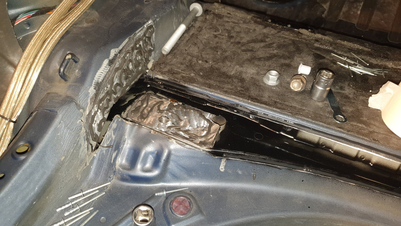
4. Although the plates are shaped to match the floor, some additional shaping is required in order to conform 100% to the contour of the floor. I used a small hammer and a block of wood. End result should look like the below.
5. As per instructions, the 1st layer of Sheetmetal needs to be removed where the holes on the plates exist. This is to access the 2nd layer of metal and weld the plate on that.
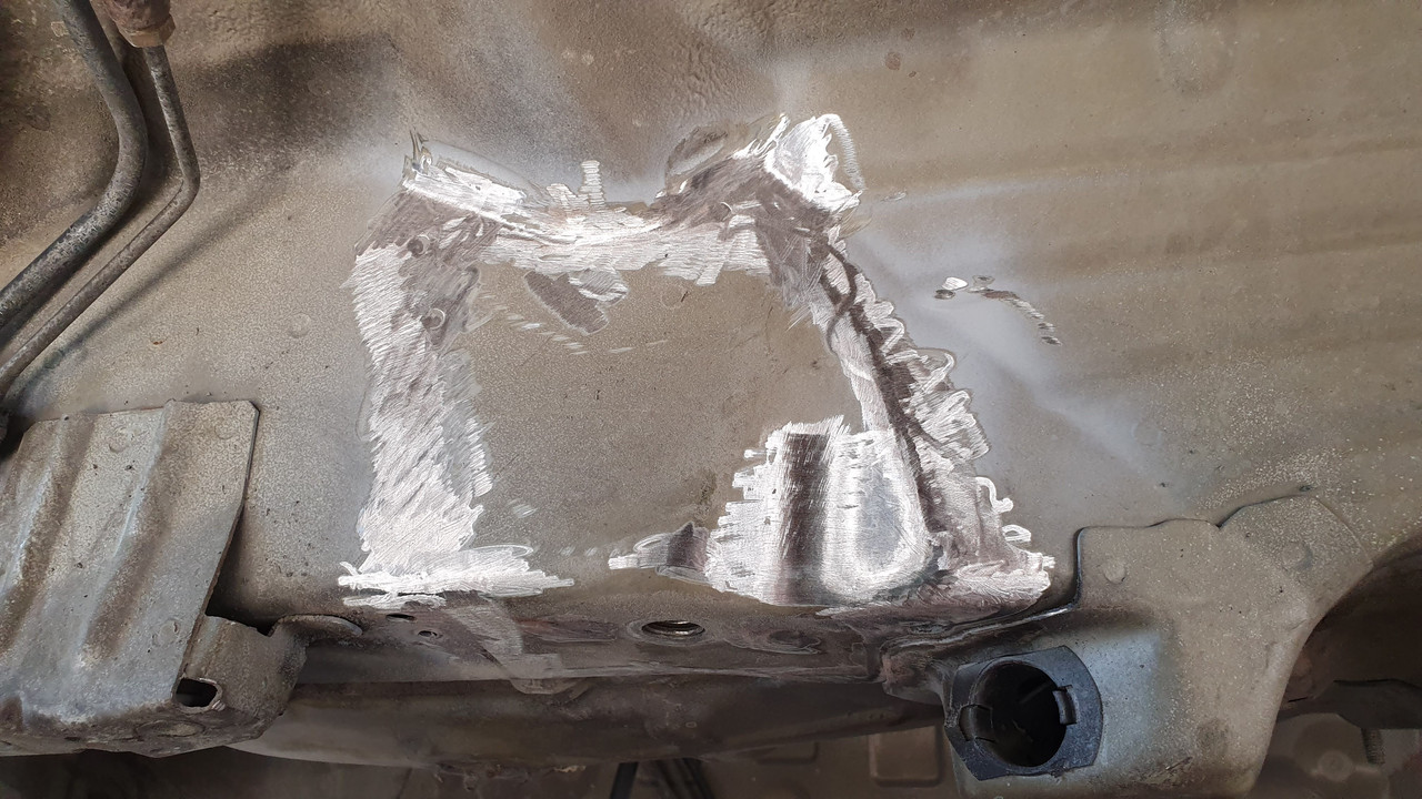
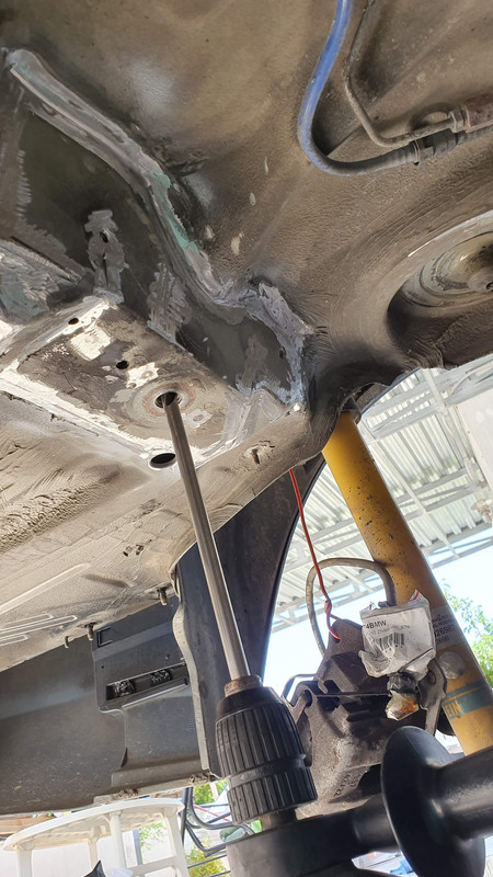
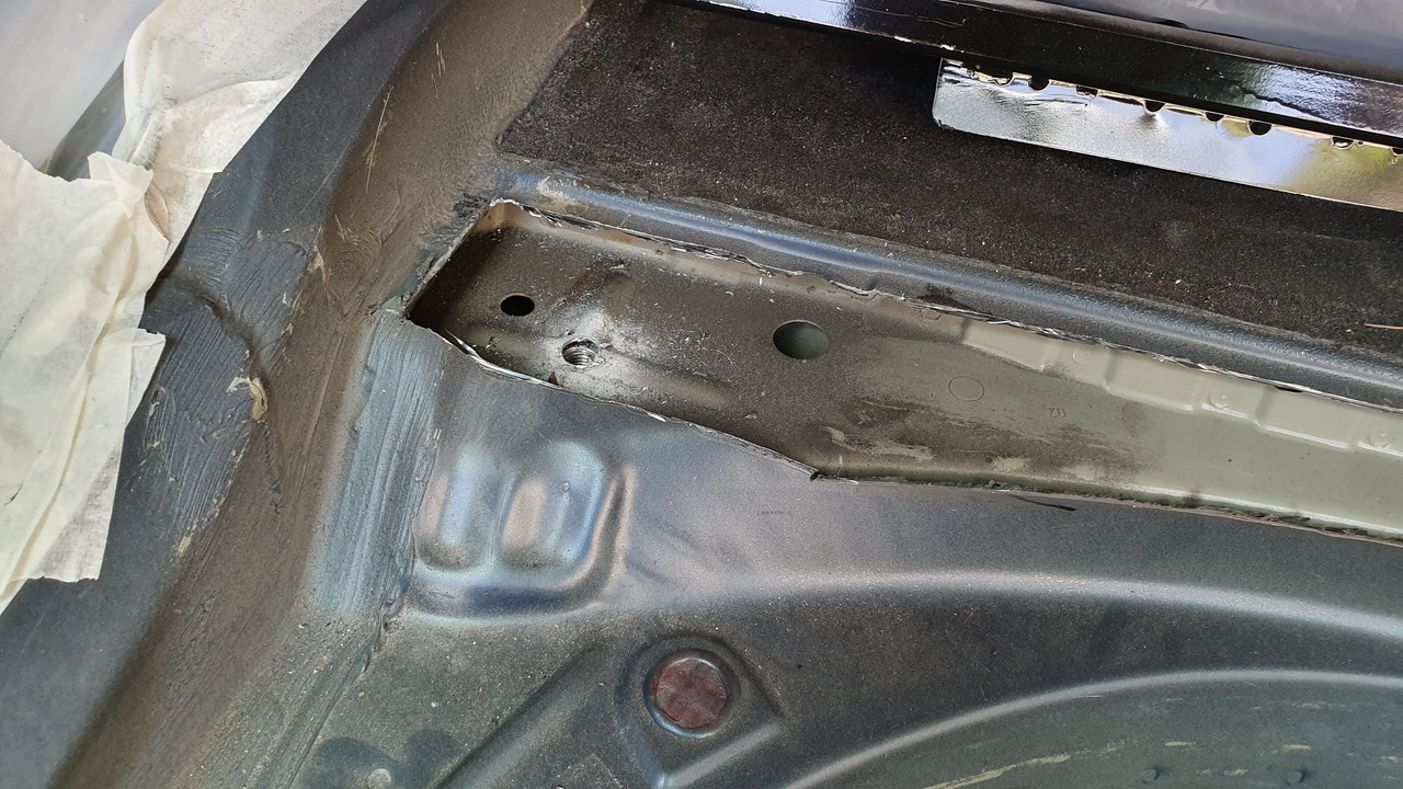
6. Surprise, during the insulation removal, the first crack is revealed. This was not visible at all. You can see the cracked metal and a hairline crack being formed as well.:
7. Made 2 small holes at the crack ends so that it doesnt spread. During welding, the crack was repaired and grinded so that the plates sit on top of it flush.
8. Welding in progress. For this, I brought a friend of mine to do the job. Used a Kemppi Minarc 180 MIG weld. We did the work taking mini breaks to allow the metal to cool down. Tip: I had a fan inside the trunk blowing air outside. Lots of smoke from the weld will enter the car and the fan helps to push it out. Helps to avoid odor staying inside.
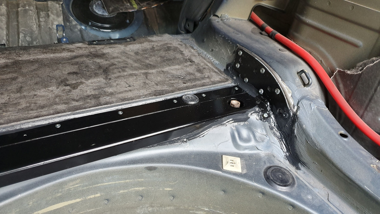
9. Use a grinder to smooth any imperfections, to make this look more aesthetically pretty.
At this point, the installation of Redish Motorsport plates is considered complete. Treatment of the welds and other painting is in the last steps once all of the metal work is complete. With the Redish kit, there are 2 additional plates that cover the holes opened within the trunk to access the subframe mounts top side. Since we are using the Vincekit, those plates are not needed.
Installation of Vincebar kit [Phase 2]
1. Remove the factory front subframe studs. Use the 2 nuts removed before, wedged together to remove the stud. It came out pretty easy. Repeat on other side.
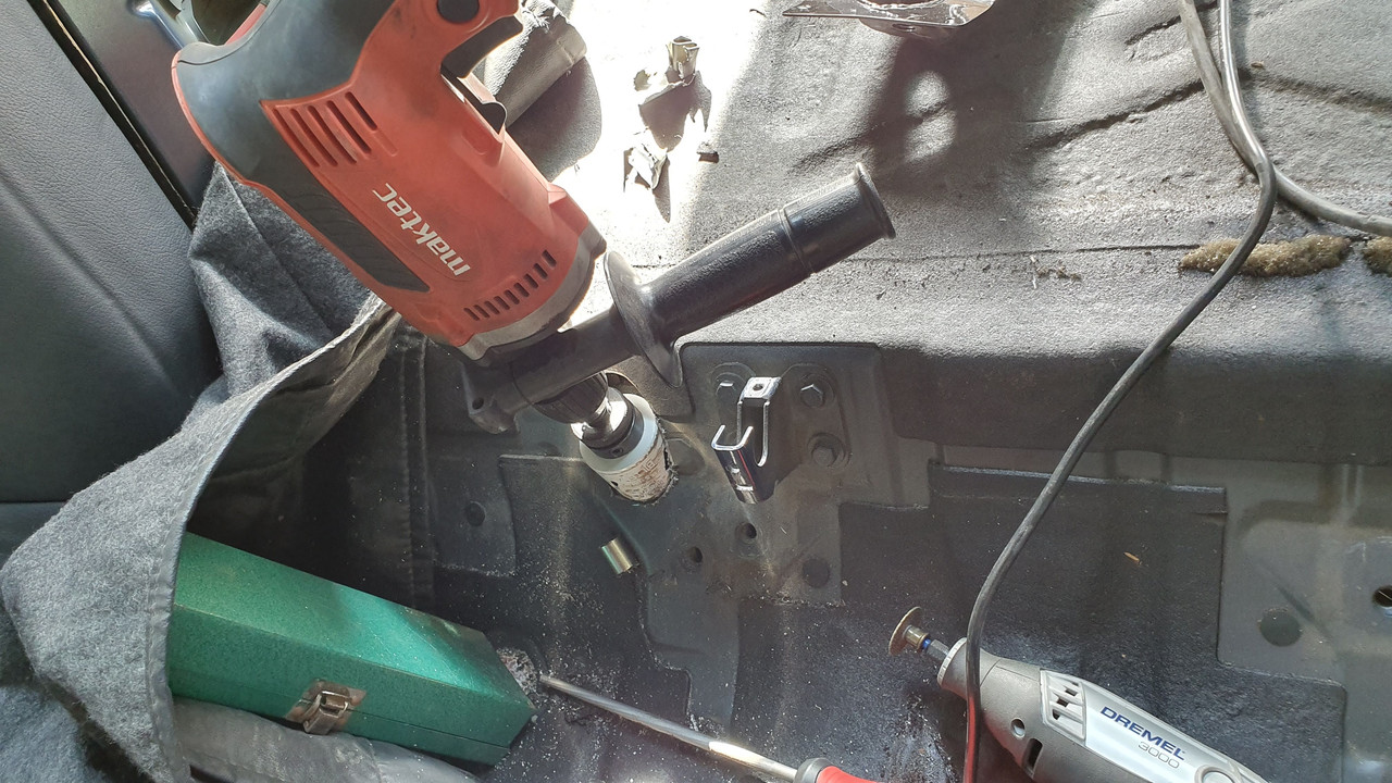
2. Use the supplied drill bit to drill through ALL 4 subframe mounts. The objective here is to create a hole that will be threaded and also mark the positions inside the car for the installation of the kit. There is about 10mm of threadable material in the mounts.
3. You should be able to drill vertically (the existing holes/threads act as a guide) and the end result should allow you to see the car inside.
4. Use the supplied M12 tap to create threads in the remaining subframe mount. Use compressed air / brake cleaner afterwards to blow any metal shavings away.
For now, the work under the car is complete. Moving to prepare the body inside the trunk
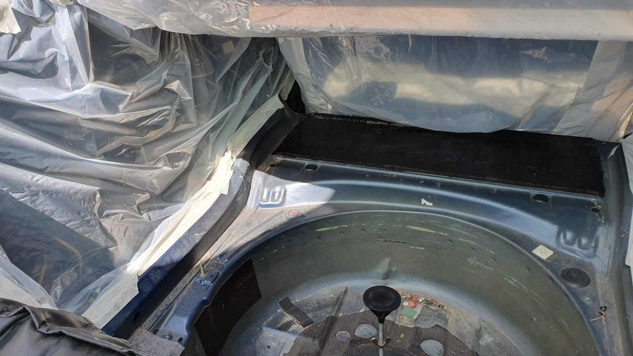
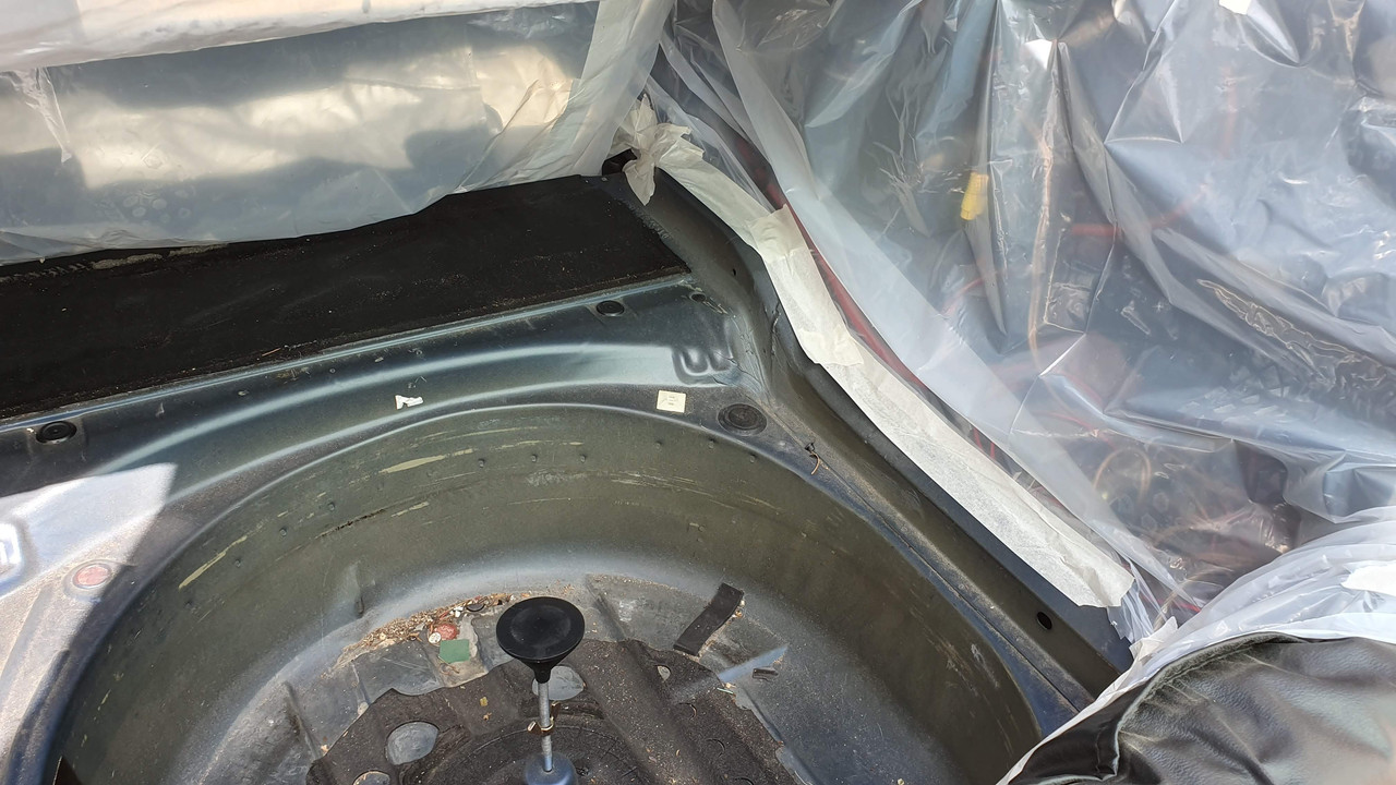
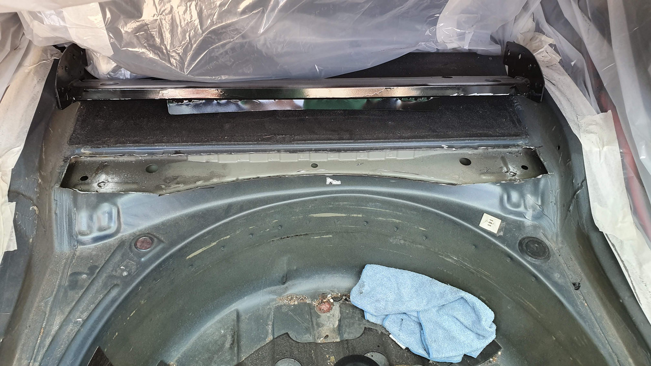
5. The holes where the long drill bit came out will show on 4 points within the cabin/trunk. If you didnt remove the rear seats, you are going to need a new upholstery.
6. Use the removed studs and thread them into the trunk rear mounts as seen below. This is why it is important to create the threads before moving to this step. This is to create a guide for the Vincebar to sit on and allow to mark the cutting area correctly. Measure twice, cut once.
#####pic limit#####
7. Mark the initial cutting area following the contour of the vincebar:
8. Reseat vincebar and mark the remaining cutout to follow the shape of the vince bar
9. Use a marker and the cutting disc to further cut the wheel well area so that the cutout is at the same level as the inside metal. You can see on the left side some shaving of the inner metal as the cutting wheel surface touched a bit.
10. Use a Dremel with a quality cutting disk to make the more detailed cuts around the frame rail area etc.:
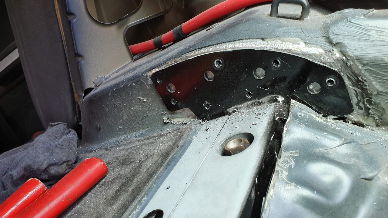
11. Reseat bar and mark the 2 endplates over the frame rales. Cut between the frame rail and the sheet metal and also grind away all paint to expose bare metal.
12. Cut through the elevated section of the mount, creating a T-cut. Use a hammer and a punch to even out the surface. This is to allow the plates to sit flush. Watch not to cut through the thread. Use the M12 tap to make another cleanup round to ensure the thread is proper.
Use the supplied plates to mark the area to grind. The plates will be epoxied here. Grind away until rough bare metal is achieved.
13. Test fit again. The lower trim of the vincebar, that goes around the wheel well should be on the inside part, not on the outside as in the picture. It was corrected afterwards.
14. Use a file, sandpaper, grinder, etc to cleanup the cuts, make it pretty, ensure the bar goes vertically down to the mounts and there are not obstructions.
15. Vacuum everything! Please do. The grindings are magnetic and get everywhere.
At this point, the vincebar is ready for installation.
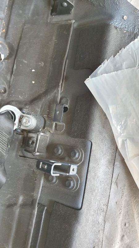
16. Move to the front subframe mounts now. Use the supplied 51mm holesaw and the supplied guide rod to cut through the sheet metal. The guide hole is already there from the bottom drilling. For ease of access I removed both seat belt buckles and ISOFIX. T50 Torx.
17. Bolt down the 2 reinforcement cups using 2 wheel bolts and a washer. Mark the area to be grinded, use a small hammer and a piece of wood to mold them to the contour of the sheet metal.
#####pic limit#########
18. Once all parts have test fitted, the metal preparation needs to be performed to ensure a proper bonding of the epoxy. For this, I used the grinder wheel and let it jump on all surfaces to create a rough finish. Afterwards, I washed everything with brake cleaner to remove any oily and other residues.
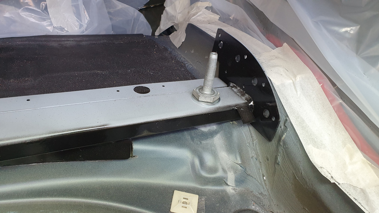
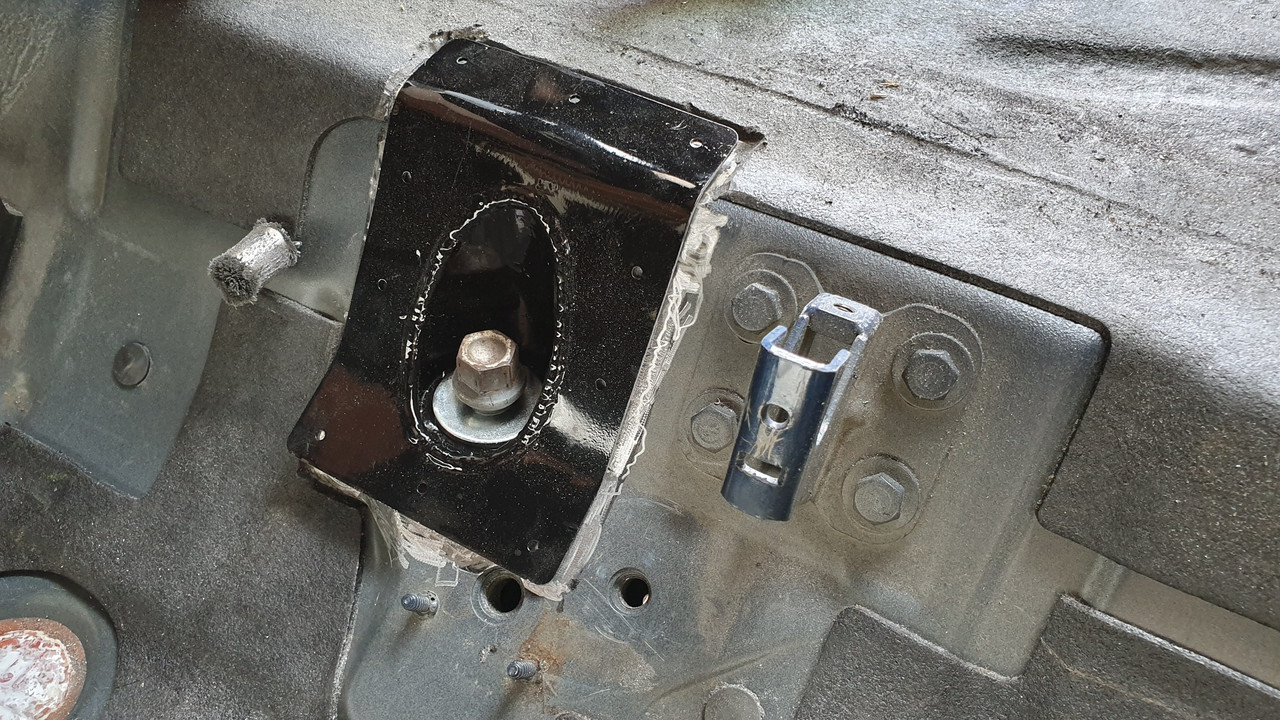
19. Install the supplied studs with the aluminum washer into the 2 front subframe mounts. I used a 2-nut method to bolt them in. The correct length of the stud to protrude is 95mm from the body. This ensures enough thread within the car and enough thread for the bush to be secured.
20. Bolt down the vincebar to the rear section and the 2 gussets to the front section. Use the supplied drill bits (2 different sizes) to drill wherever the holes on the plates exist. The rear section holes need to be aprox. 15mm of depth, so the drill bit was marked.
21. Test fit that ALL rivets can sit in the final position.
22. Remove vincebar and gussets and clean again.
23. Attach the epoxy cartridge to the dispenser, open it and install the mixing nozzle. Have a heavy-duty riveter ready with the correct diameter head installed. The rivets are steel and very hard to snap.
24. Start by applying epoxy on all surfaces to be glued. Use the supplied brush to spread the epoxy to make 100% surface coverage. I emptied the remaining cartridge to places where some unevenness was present.
25. Install the remaining rivets on the remaining parts of the vincebar, tying it to the wheel well area and to the upper sheet metal. I also used a lot of industrial seal to close any gaps and make it look more tidy. If you need it to be factory looks, then a bodyshop can fix it.
26. Once the gluing and riveting is complete, it is now time to take a break. Step away from the car and leave everything there, bolted down, for at least 3 days. This will allow the epoxy to cure and permanently fix the reinforcements.
Installation of Swaybar reinforcement kit [Phase 3]
I had the rear/left mount snap a few months ago at the welds, from metal fatique and the right mount started to tear the subframe metal itself, towards the rear/right bush. The reinforcements take care of these issues. Its a must especially if you use aftermarket antiroll bars. The factory slots remain untouched.
1. Clean all surfaces of the subframe, from loose particles and rust using a metal brush / wheel.
2. Install the reinforcement plates and bolt them down using a nut/bolt so that they stay secure.
3. Apply a uniform, perimetrical weld, fill any cavities.
Fixing of other things while we are there [Phase 4]
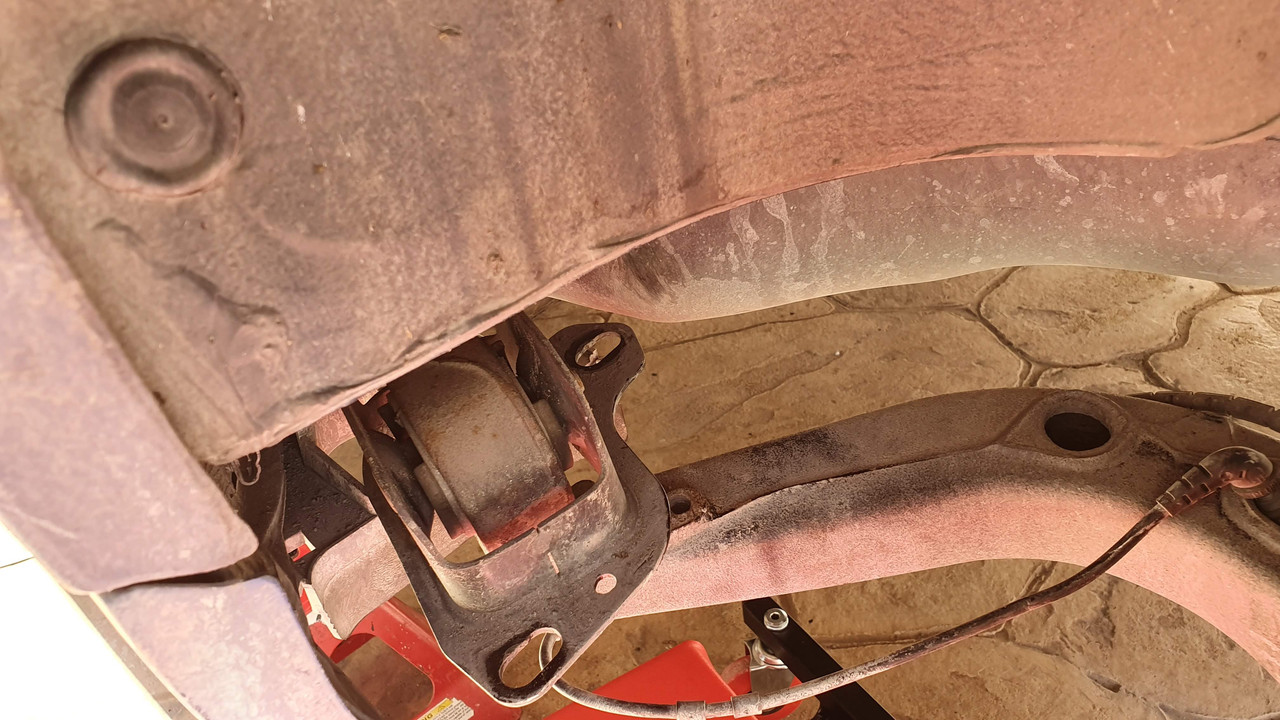
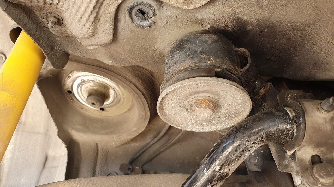
Repair of rear differential mount. As seen from the picture, a crack has started to form. If I was going to change the diff bushing Id have done a better job, but the welding produces a lot of heat and would likely destroy the bush.
Painting / Insulation [Phase 5]
Treatment of all parts with Rust-oleum paint-on-rust / rust prevention paint. I did 3 coats of pant and allowed to fully dry. This prevents rusting of all exposed metal. The insides of the Redish plates were spray painted using high-temp paint. Hopefully it survived the welding process.
####pic limit#####
The next step is to use proper underbody protection; a bitumen-based product that is very thick, and creates a weatherproof (also soundproof) coating on the surface applied. This is the same as the insulation used by the factory. I was not able to find the same color so I went with black. It can be applied using a brush, as if youre applying grease. I did 2 coatings, which made a thicker than factory layer. It does need 1-2 days to allow installation of nearby parts. 1L is enough to do this job plus touchups. I found that the area of the frame near the spring pads was also starting to rust, so I also applied anti-rust paint and underbody coating.
At this point, you can start the re-assembly process or perform more maintenance/repairs. The subframe with everything attached can be rolled back in place and start bolting things down, exactly the reverse process of removal.
The 2 front bushes on my subframe were shot, so it was logical to have them replaced. All of the torque values of this process are in the embedded PDF document, taken from TIS.
1. Removed brake disks (to refresh handbrake components)
2. Disconnect halfshafts (E12) from differential
3. Removed trailing arms / control arms from the subframe, both sides, 18mm
4. Removed differential 2 bolts (front) and the huge, 21mm rear bolt (170Nm), set the diff aside.
Subframe follows with cleaning and rust-proofing, to cover all welds and existing rust.
1. Cleaning with degreaser / pressurized water
2. Paint
***8195;
Part 3: Assembly
The assembly process is exactly the reverse of removal.
1. Install the fuel tank. Slide it in place, assemble the 2 straps, then the middle 13mm wide bolt. Reconnect fuel lines and also install the fuel neck. I chose to replace the fuel neck flex hose and the gas door gasket. Ensure the peripheral connections are also nice and tight (fuel carbon cannister).
2. Support the sub frame and everything else left. I used a motorcycle lift, it worked great but make do with whatever you have handy. Slowly roll the subframe below the car and lift it until it goes to the correct position. This is if you want to do it with everything pre-assembled.
As mentioned, in my case, after removing the subframe and finding worn bushes, I took everything apart, so I was left with a bare metal subframe.
a. Bare metal subframe (with preinstalled new bushes)
i. Install subframe on rear chassis. Install 2x nuts (temporary) and 2x bolts (permanently)
ii. Install left & right trailing/control arms assemblies, at the same time sliding the handbrake cables to the body.
iii. Install antiroll bar brackets (if they were removed) on spring mounts (easier when springs are not there)
iv. Install springs. I took note which was left and which was right.
v. Bolt rear trailing arms to body. Use the marked areas to get as close as possible to alignment. I had to use a hydraulic jack to push the trailing arms in place as the springs need to be slightly compressed.
vi. Install the differential and connect the halfshafts. New bolts as per TIS.
vii. Install brake disks
viii. Install calipers and bleed system
ix. Connect shocks
x. Install the sway bars
xi. Go inside the car and clamp the handbrake cables, adjust handbrake.
3. Install the driveshaft. Dont forget the bitumen anti vibration over the center support bearing. Align the driveshaft so that its on the diff flange and on the guibo. Bolt the guibo, then center support bearing then differential.
4. Install the heatshields
5. Install the exhaust. First slide the front section in the 4 studs coming out of the headers, then middle section, then rear section.
6. Connect left/side wiring
7. Install plastic wiring protections / covers (left/right)
8. Lower the car and drive it to settle everything down.
9. Check for leaks etc.
10. Get an alignment.
Enjoy.
Member
Wow, amazing write up!
Im also doing a full rear end refresh with plates and Vinces front gussets cups! This will really come in handy when I start installing the gusset cups.
Thanks!
Sent from my iPhone using Tapatalk
 Posting Permissions


 Reply With Quote
Bookmarks