
 Member
I've come across a lot of threads with CCV operation in M52 and M54 engines, but there is not much info about older, M50 engines.
I need help understanding how everything flows. The goal is to get rid of oil in the intake boot and manifold. I will be using a catch can as a solution. I just need to understand the operation in a M50 engine.
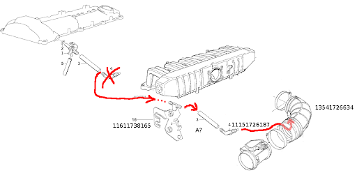
1. There are 2 hoses running from the valve cover port:
Smaller hose that connects to the intake manifold behind the throttle body.
Larger hose that connects to the air boot in front of the throttle body.
What is the reason for running both hoses? What is their function?
2. Unlike M52/M54, it seems that M50 do not require negative pressure in the crank case in order to seal the rings properly.
Does ventilation occur due to positive pressure in the crank case?
3. A lot of PCV videos/guides show that ventilation occurs due to fresh air flow through the crank case, that picks up all the vapors.
Where is the inlet for that fresh air located, in we only have an outlet through the valve cover port?
4. Is there any vaccum created and necessary in this circulation implementation on M50?
Any information that will help shed some more light on PCV in M50 is welcomed and highly appreciated. But please OBD1 M50 implementation only, let's not mix with CCV in M52/54 which is completely different beast.
Thanks!
Member
I have an m52 but I should be able two explain the m50 setup. Fresh air is never sucked into the crankcase, only positive blow-by gasses are present after getting past the rings. Those gasses are sucked into the intake manifold via the hose that connects after the throttle body. The other hose that connects in front of the TB is a carrier gas that aides in sucking up the oil vapor in the other hose (you can delete this line when switching to a catch can).
Attn. NEWBIES: Use the search feature, 98% has already been discussed.
Click the search button, select "search single content type", select the "e36 sub forum" specifically, try the "search titles" then try the "search entire posts".
Member
Thanks Eric!
Can you please elaborate on the bigger hose, that connects into the air boot between MAF and TB? Does it just take the extra load or has a separate function? Also, it seems that the hose going behind the TB has a very small diameter for the job (compared to hoses used on catch cans)?
Do you know if the connector at the valve cover is just a pass through for both hoses and they communicate?
I just don't get why there is this 2 hose setup before and after the TB when the air boot (between MAF and TB) has a bypass hose to ICV that goes to the same spot where the smaller breather hose connects to manifold? What's the point?
Thank you very much for replying!
Member
The bigger hose takes measured air (measured by the MAFS) that goes to the connection at the valve cover and then that air runs up to the manifold via the small hose. That air simply helps the oil vapor air (air is blow by gasses) to flow better and clean that smaller line and help it from clogging. Its called a carrier gas, its just helping move that dirty air. Yes, your idle air control valve also brings measured air to allow the engine to idle. They probably use a smaller hose to restrict the flow but increase it's velocity, to help keep it clean and flowing.
When you make or buy a catch can, you would block off the connection at the intake boot and not use that line at all (remove the large line). Use a new hose at the valve cover (diameter doesn't matter but you don't want anything to clog), that line will go to the catch can and should terminate inside the catch can internally around the half way point. The hose leaving the catch can should leave at the very top and then run up (needs to be orientated properly) so it has to be at the top of the can and go up to the manifold connection. Inside the catch can it should have something with a lot of surface area to catch and allow the oil to condense onto, something like brass wool that's been pulled apart (fluffed up). Finally the can should have a drain at the bottom to occasionally drain the oil. I don't know what people do with the oil, if it's synthetic you can probably put it back into the engine, whatever you do don't pollute with it.
- - - Updated - - -
Something like this to put inside, but this is like a 10pk, you would only need one stretched out.
https://www.amazon.com/Thermaltronic...dp/B00NS49LPU/
Attn. NEWBIES: Use the search feature, 98% has already been discussed.
Click the search button, select "search single content type", select the "e36 sub forum" specifically, try the "search titles" then try the "search entire posts".
Member
If I understand correctly, the air flow direction inside the larger hose is from air elbow towards the connector on valve cover and then through the small hose into the manifold? Does that mean that all blow by gases always bypass the TB directly into the manifold?
Member
Can you please clarify why is it suggested to delete the "helper" airflow? As I see it, deleting this passage will create negative pressure in the crank case due to vacuum in the intake manifold? And if we leave the large hose in place, then crank case will be releasing its pressure at its own pace, while the intake vacuum will keep sucking air through the large hose, therefore calibrating the ecosystem? No?Originally Posted by Eric93se

Member
If it were me, I would go with something like this. You could still add the mesh but it may not be needed, it would help the design though. Other draw back is the size, I don't know how long it would take to fill it. You wouldn't want to use any of the designs with the breather filter at the top, that would let in un-metered air.
https://www.ebay.com/itm/New-Black-A...4/302580119651
- - - Updated - - -
The manifolds job is to create that negative pressure, it's there to suck, while the crankcase blow-by is creating the blow.
- - - Updated - - -
In the M52 there is no helper line. Blow-by gasses are directed to the oil separator valve, oil vapor hits a diaphragm and drips down to a line that runs to the oil pan, the somewhat clean blow-by gases then travel around the separator valve and get sucked into the manifold to get burned.
- - - Updated - - -
If your small line gets clogged, oil vapor will go through and collect in your large line and collect in whatever it connects to. In the M52 the drain line from the oil separator can get clogged with sludge, the oil and vapor will all go into manifold (similar to your M50). On E46 cars they have an different setup that's actually worse because when it clogs it will choke out the engine, I don't know what the design looks like only that it wreaks havoc when it clogs.
Last edited by Eric93se; 11-06-2018 at 06:40 PM. Reason: spelling
Attn. NEWBIES: Use the search feature, 98% has already been discussed.
Click the search button, select "search single content type", select the "e36 sub forum" specifically, try the "search titles" then try the "search entire posts".
Member
That could be beneficial, actually, hmm... I agree that the blockage in the small hose will cause the blow by to exit via the large hose, but that is the "safety valve" right there. Isn't it much better than just let the pressure build up in the crank case to the point where seals are leaking?
What is your opinion? Thanks for keeping this conversation going!
Last edited by make it easy; 11-06-2018 at 06:53 PM.
Member
No pressure is going to build up, not sure where you got that from. With an oil catch can (without the larger hose used) will have dirty/oil air leave the valve cover, enter the oil can and get cought/condensed in there, then somewhat clean air will leave and get sucked into the manifold to get burned. That is as simple as it gets. Some people don't let the engine suck in the somewhat clean air and simply put a filter (air filter also called breather filter or something) at the top of the catch can and vent it out.
Attn. NEWBIES: Use the search feature, 98% has already been discussed.
Click the search button, select "search single content type", select the "e36 sub forum" specifically, try the "search titles" then try the "search entire posts".
Member
You mentioned that
If your small line gets clogged, oil vapor will go through and collect in your large line and collect in whatever it connects to.
So I assumed that if you eliminate the large hose, and the small hose gets clogged, then the pressure will build up in the crank case.
Now I do understand that the catch can should overcome the clogging issue, at least past the catch can, but then why remove the large hose if clogging is unlikely to occur?
All I am trying to figure out is the benefit of removing the large hose with a catch can setup. Isn't it better if I just cut the small line and added the catch can to it, no other modifications?
Member
It's not necessarily better but you can "I just cut the small line and added the catch can to it, no other modifications?"
People remove stuff that isn't necessary. On my car I removed a bunch of vacuum lines, that improves the engines vacuum and makes leaks a lot less likely.
"So I assumed that if you eliminate the large hose, and the small hose gets clogged, then the pressure will build up in the crank case." No, because the large hose simply vents to the main intake, no pressure is created.
Attn. NEWBIES: Use the search feature, 98% has already been discussed.
Click the search button, select "search single content type", select the "e36 sub forum" specifically, try the "search titles" then try the "search entire posts".
Member
Thanks Eric for clarifying!
~Max
Member
Is the E34 m50 same as the E36 ?
http://www.johnrogers.com.au/bmw/cra...ntilation.html
Member
Great info. Following this thread as I ordered a catch can to run on my OBD1 M50. Looking forward to eliminating some of these "unneeded" vacuum lines.
Member
Follow up after yesterday's discussion. My findings.
I inspected the valve cover connector and it appears that the 2 lines are separated. The large hose connects to a nipple that is basically a pass through tube, straight into the valve cover. The small hose connects to a nipple that has a port into a chamber inside the connector. See pictures.
20181107_091109.jpg
Ok, so far makes sense. Let's take a look through the hole on the valve cover. Wait, what?? Further inside, the orifice narrows down to a smaller hole, through which only the long tubing from the large hose can fit! WTF?? Why? Why do we even have a small hose with a chamber in the connector if it has nowhere to go??
20181107_090401.jpg
Now another important thing to mention is that the hole doesn't go right under the valve cover. Instead, there is a sealed chamber under the valve cover. Referred to as "Air Baffle" on PelicanParts website. I couldn't find any other references and I have no idea how it works. Some other valve cover baffles act as oil separators, but I have no idea if this one does the same job. I don't have my VC out to inspect.
pic6.jpg
So far I know that:
1. The chamber for the small hose goes NOWHERE. So no idea how anything can flow through the small hose...
2. Valve cover port narrows down to a smaller orifice through which only the "large hose tubing" can fit.
3. This orifice enters the sealed chamber under the valve cover referred to as Air Baffle.
I'll keep digging...
Last edited by make it easy; 11-07-2018 at 06:00 PM.
Member
UPDATE: Two things.
1. Fact.
The diameter of the plastic tubing that runs through the valve cover orifice is 10 mm. I wanted to confirm the size of the orifice. So I grabbed a socket of similar size, just a bit smaller and applied a layer of electrical tape to match the diameter of the orifice. Ran the socket through the orifice to make sure it was a snug fit. Measured the diameter of the socket w/tape on it: 12mm.
20181107_090934.jpg
20181107_091024.jpg
The orifice is bigger than the tubing by 1 mm all around. Meaning that the chamber from the smaller hose DOES have access to the same air baffle space.
Time to figure out how vapors get inside the air baffle chamber.
2. Assumption.
I think that there are some hidden lines going from the access ports (encircled in the pic below). This network then goes into the air baffle chamber. I suspect that if we open the cover, we'll see a few entry ports. Then there is a filter inside that is supposed to stop most of the oil, and it does so, but not all of it. I've seen on other auto forums people saying that after removing those baffled chambers (in hopes to get a better ventilation), they ended up flooding their intakes with oil.
pic6_1.jpg
There is only one way to confirm this: take out the valve cover and open this mysterious box...
Member
Inside the valve cover that is going to be an oil separator. The fact that the small link is so narrow means they expect fairly clean air to exist the valve cover. But over time the small line will clog and then the oil vapor will travel through the large line and collect, get on the throttle plate and the idle air valve.
- - - Updated - - -
There's two bolts on that chamber so its serviceable, its meant to be cleaned of sludge.
Attn. NEWBIES: Use the search feature, 98% has already been discussed.
Click the search button, select "search single content type", select the "e36 sub forum" specifically, try the "search titles" then try the "search entire posts".
Member
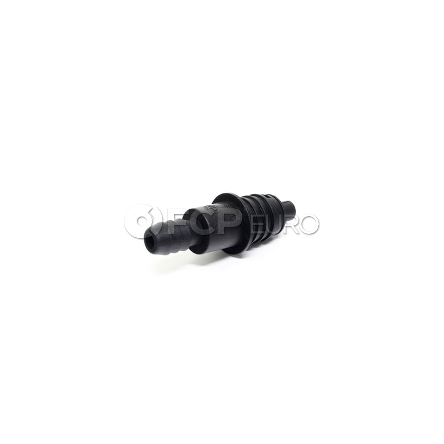
I have a 1995 325i and I ordered a ccv breather kit for the M50 that came with the valve cover connector and the small and large hoses you have mentioned, but it also came with this connector, which I can’t seem to find where it goes. It has a chamber on the inside clearly because you cant see through it. Neither the small or large hose connect to anything like this on the other end. Any idea what this is and where it belongs?
The valve cover connector and both hoses were caked with old oil build up on the outside but nothing was blocking the inside of the hoses or the connector. I could see some very light build up inside the hoses but could see through end to end on both hoses. The car has been running rough off and on. Some days it’s great and others it wants to stall at every red light and breaks up under power, oddly especially when I hit bumps??? I was hoping replacing these lines and connectors will solve the issue. Haven’t button everything back up yet till I know where this piece is meant to live. 7EEA3018-C8CF-46F0-94BB-F08A839DD7B1.jpgCFFAF59D-626F-42BA-AE59-DD04F10668A7.jpg108C2200-55FE-4908-8F7D-29942E06AD60.jpg
Member
1995 Valve cover vent
Small hose goes under the intake manifold to a vent tube
and the large hose is under the intake boot elbow with that adapter connector.
Member
Thanks for the help. The large hose was connected to the throttle body in my car and the connector that is there for the large hose was much different than the piece I have pictured. I was able to pass a small wire straight through the hole inside the throttle body and straight out the connector so it isnt chambered like the piece I have pictured.
Member
A newer version has a one piece large hose right to the intake boot like you show I do not think there is a baffle in it either. I would prefer one since most PVC valves only draw in when a vacuum is present. An open connector is a possible intake leak
the newer diagram E36 95 but the reducer is not bent
Sponsored links
Last edited by gc325is; 06-29-2021 at 08:52 PM.
Member
I replaced mine with this and the valve cover and always notice the hose still has oil film where it connects to the connector. It suggests the connector doesn't have a good seal to the valve cover (which is also new). Anyone know if this is a common behavior?
the newer diagram E36 95 but the reducer is not bent
Member
The design of the system always has the hoses connected from the engine to intake. There is no "PVC valve" to open or close like other cars. Thus oil vapors are being drawn in while at idle or at open throttle. Oil is not separated well and will get on the hoses. Old car will have increase blow by gas and more oil will collect and burned. E46 have a oil separator added but that system seems to have problems too. What you do not want is an air leak in this system. Note this also includes the connection under the intake manifold vent tube.
Member
I removed mine completely and just ran the valve cover hole to a catch can. I made a new fitting that seals to the valve cover with an o ring. Its just a cylinder with a hole in the middle, no fancy stuff going on. It goes to a catch can that vents to atmosphere. The catch can fills up at a reasonable rate, and there's no more oil in my intake manifold. I replaced the little fitting on the bottom of the manifold with the rallyroad one that doesn't have the nipple for the small hose.
When I first took my throttle body off there was an insane amount of oil in the intake manifold, they might as well have run that hose from the elbow right into the oil pan. Make sure to also plug the hole in the elbow if you're going to do what I did.
I have to assume a fully working stock system would do fine, but the catch can ensures I'll never have issues and simplifies things a lot.
Member
This is my issue. literally the only part of the engine bay that has traces of oil weeping. Engine is completely resealed, new valve cover, new hoses under the intake manifold. suffice to say this is normal behavior?
Crankcase
 Posting Permissions


 Reply With Quote
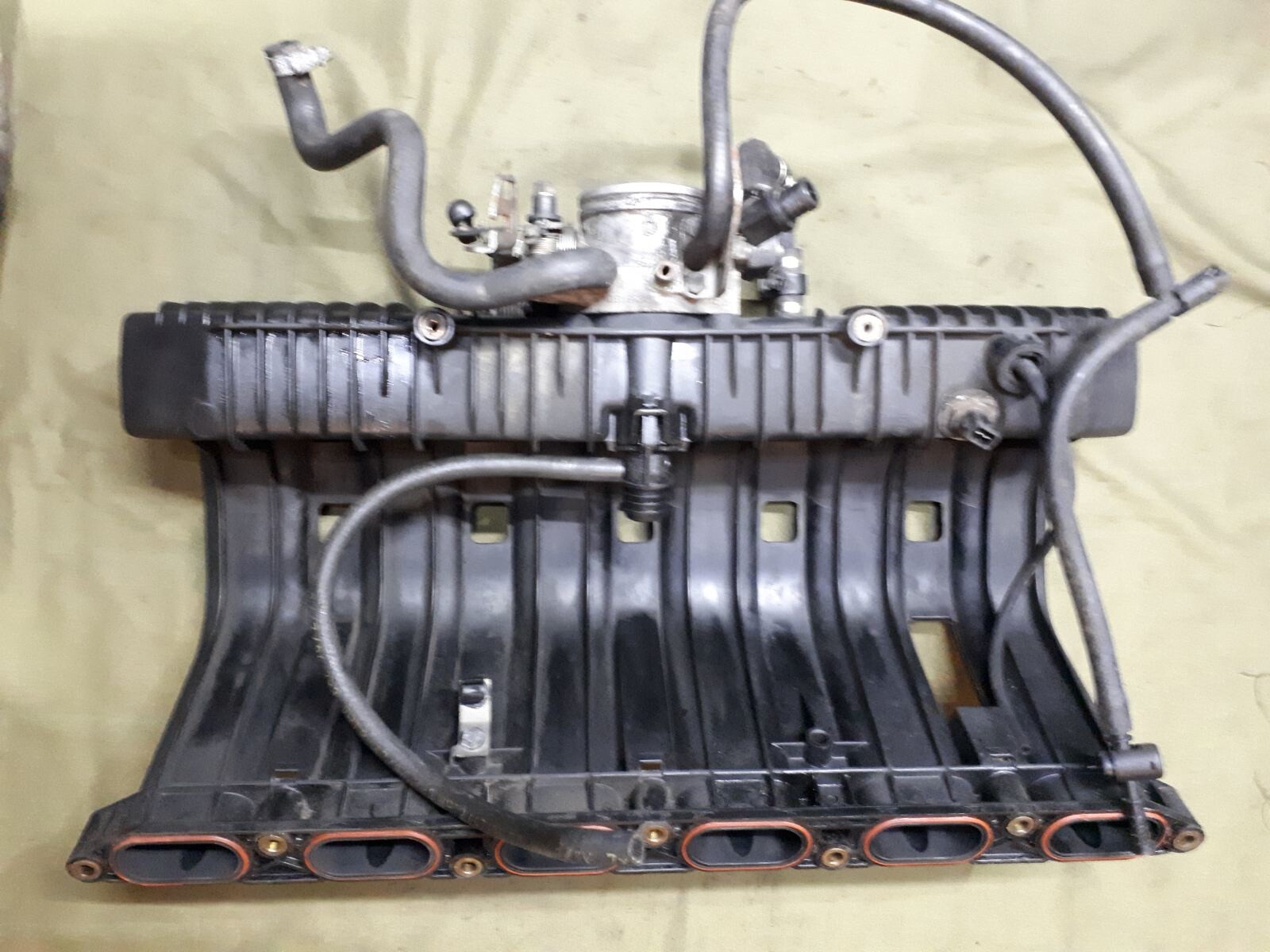

Bookmarks