
 senior LOUNGE creator
Awesome progress Scott
Sent from my iPhone using Tapatalk
If liberty means anything at all, it means the right to tell people what they do not want to hear.
― George Orwell
 Member
Nice cage! Mind explaining your seat and trans tunnel setup? I'm looking at caging my 97 and with my height getting the seat lower is a toppriority, but also have to be able to mount it pretty far back. Curious if you or your cage builder had any insight to share with that.
Member
Thank you!Originally Posted by 5speed300

Similar situation to you. Im 63 with most of my height above the waist; needed to get the seat as low as possible. Additionally, the seat mounts I bought shifted the seat significantly towards the door, no beauno.
Cage builder cut out the factory supports and welded in angle iron for the mounting base. Also seen it done with square stock that has helicoil inserts. To shift the seat to be more centerline, he just notched the tunnel. If you go this route, make sure you set up time to test fit the seat. Im gonna need to go back and have him extend the notched section a few inches. I sit comfortably but Id like to get it an inch farther back. Just ran out of time and couldnt test it before hand.
Member
I've really been enjoying this thread.
Member
Thank you!
Small set of updates. Just been plugging away on the harness; have the ABS, lights, and fuel completely separated at this point. I just need to order breakers, switches and few other items and put it all back together. Does anyone have recommendations on a panel to replace radio/hvac/etc area? Will likley pick up a carbon panel from A.J Hartman but would like to see if there are other options. Only other thing I found was Hard Motorsports but I was really unimpressed with their brake duct kit and would prefer to not use them again.
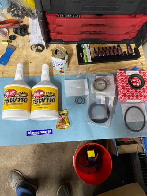
Picked up a diff and a set of scales/ramps last weekend. Diff is a DiffsOnline 3.64 4-clutch with 30/60 ramp angles. Neither of these items were in my budget for this year but I got such a great deal on them that I had to go for it; likely will cost me a race weekend but I consider it money well spent.
That's it for now. Front and rear glass should go back in within the next week. The more I look at it, the mechanical work is not too daunting so I will try to bang it out over a few ironman weekends.
senior LOUNGE creator
I have a panel for you. Shoot me a text
Sent from my iPhone using Tapatalk
If liberty means anything at all, it means the right to tell people what they do not want to hear.
― George Orwell
Member
Been a while since I did an update and I wrapped up three projects between last weekend and today so I thought I would share.
Knew I needed to get my baffled oil pan on at one point so I figured that it would also be a good opportunity to do motor mounts and would probably be easy to tackle headers with the subframe out of the way.
Borrowed an engine support bar from a buddy and got to it. Taking the subframe off was quite easy. It also gave me a good opportunity to take off and inspect all the suspension components
Getting the oil pan off was also quite easy. The hardest part was realizing after I needed to remove the PS pump as well.
With that out of the way, I turned my attention to the headers. Taking these off was not particularly hard. A few studs backed out but nothing gave me any trouble. I did soak everything in PB Blaster the night before and had sprayed it once a few weeks earlier when I was initially going to tackle this. Imagine that helped a bit.
Out with the old.
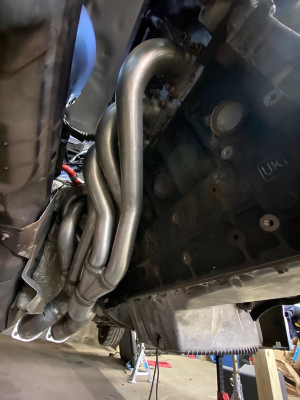
In with the new. I picked up a full SuperSprint Race exhaust back in 2017 as part of a GB. I've been waiting since then to get this on.
While getting the stock headers off was easy, getting the long-tubes on was a sadistic exercise. First, I realized I have to remove the engine support arm (that bolts to the block) to get the front set of heaters on. I honestly don't think it's possible to get these on without dropping the subframe. There just is no clearance at all. Since I had the subframe out, getting the support arm off and the headers test fitted was easy enough. Getting all the nuts back on was another challenge. I have very large hands, this made it very hard to get all the nuts back on the rear set of headers as the pipes snake close to the studs. Also, several of the studs require a crescent wrench to start the nut; the nuts are 11mm, I have a 10mm and a 12mm but no 11... and because I live in NNJ, stores are closed on Sundays. Thankfully, after the nightmare that was using an adjustable on the first nut, I realized there was an SAE size I had that was close enough to work well. Everything else went rather smoothly just time-consuming to get all 24 nuts on and tight with such limited room. After I got the headers tight I threw the engine support arm back on; the headers BARELY fit over the support arm. Check out pictures two and three below to see how "much" clearance I had. That said, I am SUPER stoked to have these on!
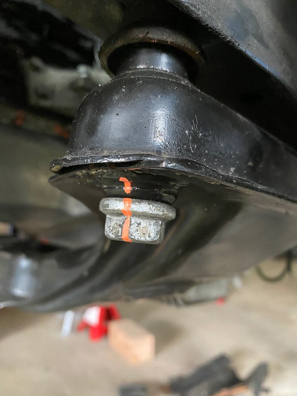
Finally, it was time to get the subframe back in. While the subframe was out, I took the opportunity to install Vorshlags Nylon motor mounts. I picked these over solid metal on the advice of a friend. Honestly, I don't remember what he said to convinced me not to go metal but in the end, he did. He and his family have been racing for 30 years so I trust his advice over my own. I was worried about the effects of heat on the non-metal so, in addition to the stock heat shield, I also covered the passenger side mount in some heat reflective fabric I got from BimmerWorld. I am also using this stuff to cover the gas tank where the exhaust crosses over.
I thought it was going to be easy to get the subframe back in but it was not. First, given its size and weight, it was hard to balance it and get the screws all in. On top of that, I couldn't for the life of me get the motor mount holes to line up. The gap it was off by was even more frustrating.
After a lot of pushing and pulling and a lifetime supply of swearing, I ended up taking the subframe back out to reaccess. I ended up removing the driver side engine support arm and loosely bolting the subframe to the body and the passenger side mount to that side's support arm. I then attached the detached support arm to the engine mount and used the longer bolts used by that mount to pull the engine into place. Worked perfectly! Bolted everything up and marked the bolts with a paint pen, and with that, I was done!
That's it for now. Obviously, there are some other things on in the pictures but I will update you on those projects once they are completed!
- - - Updated - - -
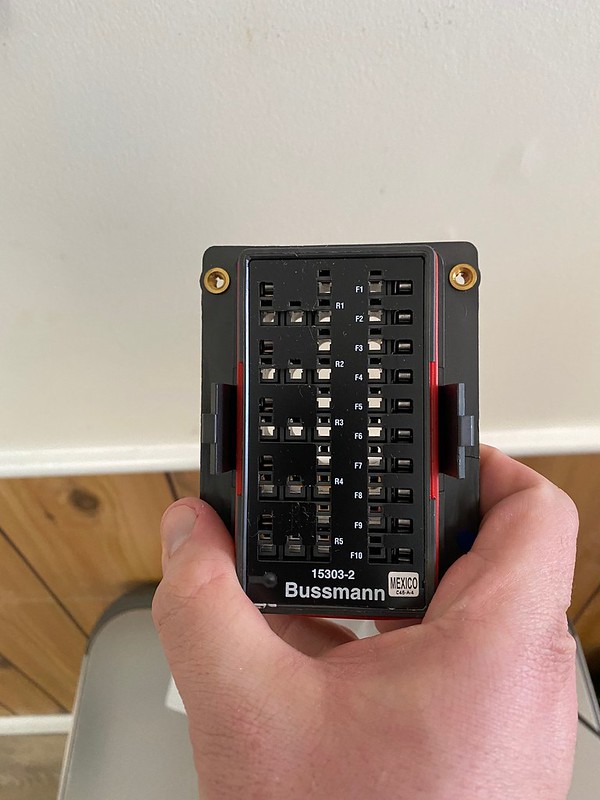
OH! We couldn't have an update without something wiring related. Picked up this Bussman relay/fuse box a few weeks ago. I am going to use two of these to run everything in the car. Super quality project, very excited to get this incorporated. If anyone is interested in learning more about it, this thread was a world of value:
https://www.tacomaworld.com/threads/...-block.399454/

Member
Your quality build continues! Nice find on the Bussman box, wish I'd known about that a few months ago.
Can the relay sockets be used with 5 connector relays?
Member
Thank you! There are two relay variations of the box, one that can incorporate 5 micro relays (pictured) and one that can incorporate 3 typical mini relays; you can get them in further variations of busses and non-bussed units. I did not realize it before but the ABS relays are more complex vs a normal 5 pin relay; because of this, I can't use this model for the ABS relays; that least that is what I think. The ABS relay is a 6 Pin that incorporates positions 30 and a 30a. I have tried searching for what the 30a is/does but the search only get items that relate to 30 amps. The ABS pump is a 5 pin but the 87a is located in a different potion (corner) compared to the normal 87a (center); I don't know if/how this changes the relay but I don't want to risk it and will just try to use the stock configuration.
The pictured box will be used to convert the headlights (2), spal fan, and defroster relays into micros since they are conventional. I want to move over the fuel pump and engine DME relays to inside the cabin but with the way they tie into the rest of the engine harness, it is not an exercise I am willing to take on right now.
Last edited by BlackHawkRacing; 04-20-2020 at 11:12 AM.
Member
Yea, that's the issue I was wondering about (the various relay-pin configurations we have on these cars). Those 6 pin relay sockets are hard to find. I left 3 relays in the engine bay (DME, Fuel Pump, and O2 sensor heat), and put the 2 ABS relays in the cabin. All fuses (got those down to 7) in the cabin.
Member
Those headers clearances give a new meaning to the thickness of a hair....
that link to the electrical info is pure gold. So many rig up unsafe and illogical wiring. Teaching beautiful and artful car electrical craft. All in a well written article that is clean and easy. Pics are bonus! Bookmarked for the V8 swap wiring.
Member
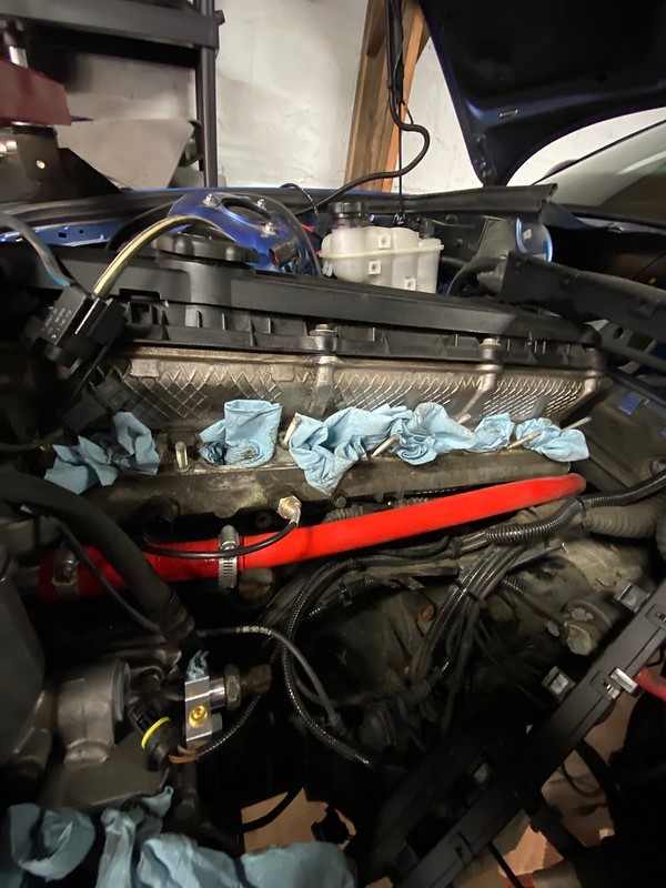
Back in 2017, I acquired the euro cooling kit from BW with plans to convert my car over from the stock cooling system. The kit, which is NLA, is pretty nice and includes the euro hard pipe, expansion tank (same as on the e30s), the radiator vent line, and the various rubber hoses needed to complete the kit. At the time, the reason I wanted to switch over to the euro system was the ease of bleeding the system, freeing up space near the radiator, and, to be honest, coolness. With the transition to racecar and deletion of the heater core and associated items, I really just wanted to simplify the system and free up space near the radiator.
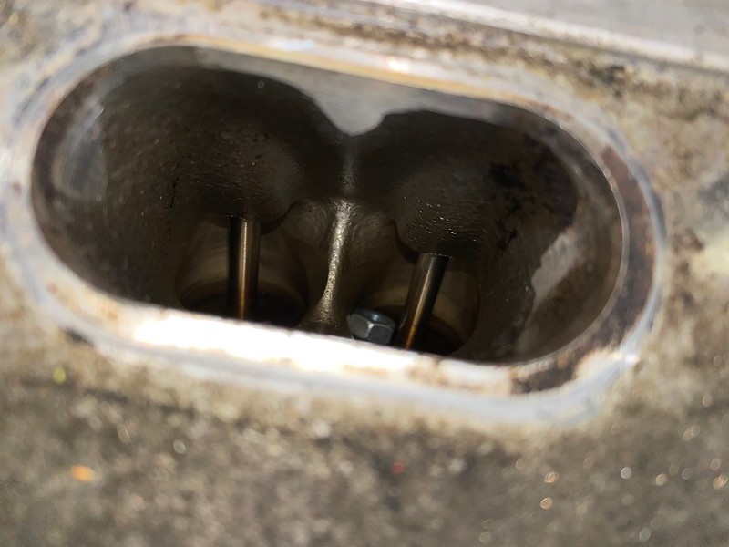
I had taken the intake manifold off to swap over the M50 and figured this was as good as a time as any to tackle the cooling project. With the manifold off the first thing I did was remove the heater core valve that directs the coolant either back into the block or into the core and then back into the block, no pictures here but it was just a few bolts and off it came (remember, all the other heater items were removed long ago). I then went about plugging the back of the head utilizing the block off plate from BimmerWorld. Top bolt was pretty easy but the bottom bolt was a bit encumbered and took some finger yoga to get it out. Plugging the hole was very easy, with the plate being flat, it was just a matter of finding the holes, and getting the bolts threaded properly; because of the position of the part, only have this photo.
Getting the US-spec hard pipe out was another hard exercise, it requires you to remove the intake manifold supports, along with some other bolts, and then dislodge the pipe from the block port, which is held in by an o-ring. This is made more difficult as the pipe spiders out under the intake manifold and is underneath all of the engine harness wiring in the area. This is the best photo I have, ignore the red hose, more on that later. The pipe ran under all the wiring you see in the left side of the photo.
To install the euro kit, on OBD-II cars, you first need to install this adaptor pipe into the hole where the US hard pipe once sat. It was at this point that I realized I had either never purchased this, or lost the one I did purchase. Thankfully, a friend had an extra. Install is pretty easy, you just scour the surface of the adaptor, spread the epoxy, and press it in hand.
After it cured, I put on the adapter hose that came with the kit and went to test fit the euro hard pipe. It was then immediately apparent that this was not going to be straight forward or easy. Here is a short video of me explaining the issue.
Between the fitment issue, and unsureness about how I was going to block off the portion of the hard pipe that would typically connect to the heater core, I abandon my plans and tried to figure out how to do a custom system. With this application, all that is needed is to run a pipe/hose from the outlet in the block to the expansion tank and also a smaller vent line from the radiator to the expansion tank. The vent line is covered via the euro kit. I don’t have any pictures but it mounts nicely just above the radiator and runs up the passenger quarter panel where the windshield wiper fluid lines once ran.
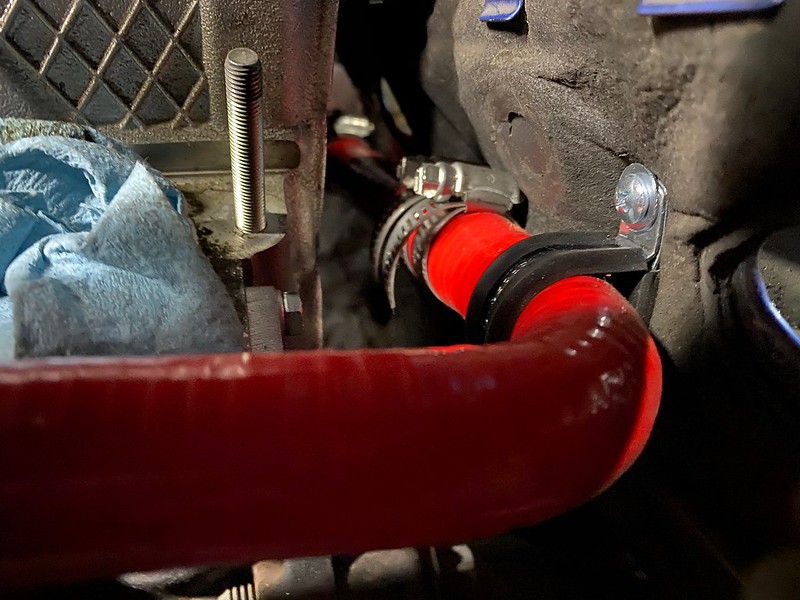
To connect the block to the expansion tank, I figured the easiest way to achieve this was by copying the routing of the Euro hard pipe. I would run a hose straight back to the firewall, around the block, and then create an S-bend to connect it to the expansion tank, which was going to be mounted in the standard Euro location by using the Euro brackets I got with the BW kit.
For sizing, I measured the diameter for the hard pipe to be 15mm (~5/8th). I also needed to get a reducer as the adaptor pipe I had already installed into the block was a bit bigger (22mm or ~7/8th). Jumping ahead for a second, in retrospect, I could have run 7/8th hose everywhere as I later realized that I needed to increase the hose size back to 7/8th to fit onto the expansion tank port; this also would have reduced the number of potential failure points as I wouldn’t need to cut and join the hose as many times as I did. I should have paid better attention when I was laying everything out.
Back to real-time: to connect everything I would use standard hose joiners and clamp it all together with worm gear clamps. I got all of the materials from Pegasus and the final BOM list was as follows:
1x - Red Silicone Hose, 5/8 x 7/8 inch Straight Reducer (Part Number: SR22.16-RED)
1x - Red Silicone Hose, Straight, 5/8 inch ID, 1 Meter Length (Part Number: SHL16-RED)
1x - Red Silicone Hose, 5/8" I.D. 90 degree Elbow, 4" Legs (Part Number: E90.16-RED)
1x - Red Silicone Hose, 5/8" I.D. 180 degree Elbow, 4" Legs (Part Number: E180.16-RED)
6x - 16mm (5/8 inch) Pegasus Pro Design Aluminum Hose Joiner (Part Number: HJ16)
13x - Lined Hose Clamp, 0.69 to 1.375 inch diameter (Part Number 3613-1.38)
3x - Cushioned Metal Cable Clamp, 1 inch dia.(Part Number 4350-1.000)
Building and install was generally straight forward: I installed the reducer to the adaptor pipe then measured out how much hose I needed to reach the first 90* elbow. I then cut it appropriately using a razor blade; I found that installing a clamp on the cut line and using that as a guide helped keep the cut straight and clean. I then installed the 90* turn to the freshly cut hose and measured how much hose I needed to bridge the back of the block, cut, and repeat.
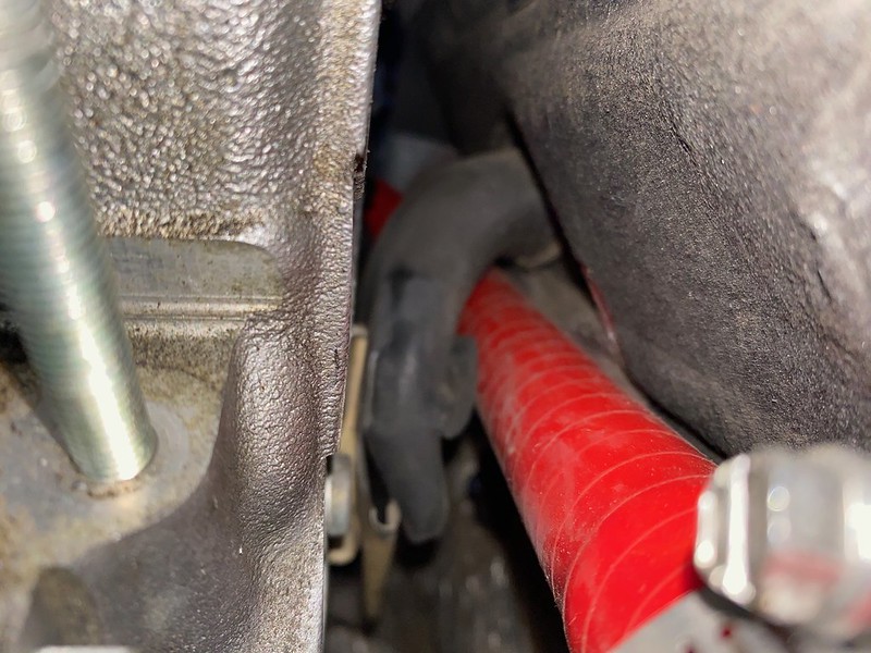
A bad shot but as you can see, plenty of clearnace between the firewall and the back of the block.
The passenger side of the firewall does a bit of an S curve around where the block ends, and with the location of the expansion tank I was going to need to follow this curve. First, I needed to finalize the mounting location of the expansion tank before trying to measure/cut any more hose.
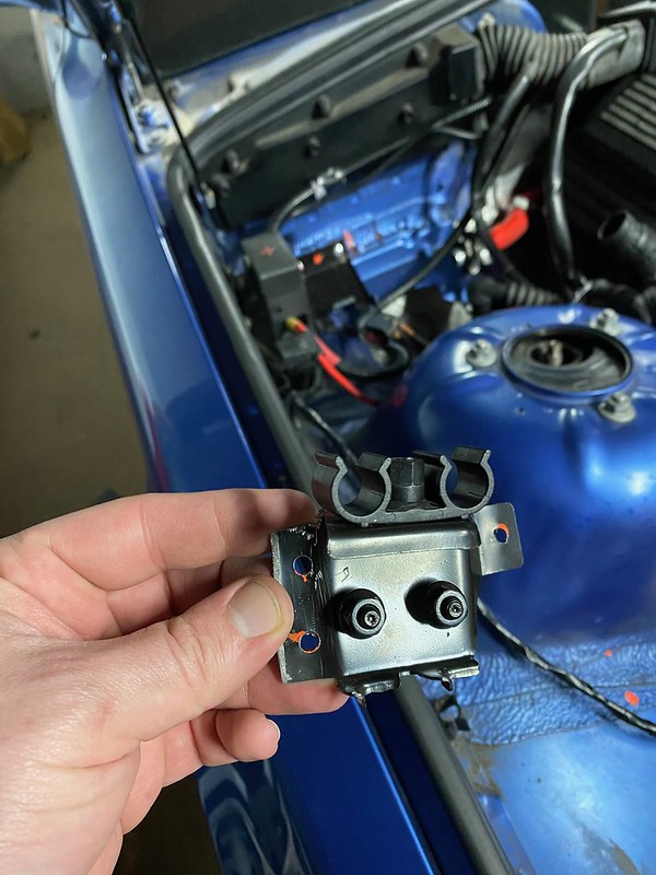
To mount the expansion tank, I utilized the OEM brackets that were included in the BW kit. One of the brackets includes the mounting for the round diagnostic port that is already welded to my shock tower, so this bracket needed to be cut to fit appropriately. My tin snips made quick work of the bracket.
Firewall Bracket:
Shock Tower Bracket Before:
Shock Tower Bracket After:
With it properly trimmed I spent more time than I care to mention trying to mock this thing up. The tank uses a duckbill to fit into one bracket and then snaps into the second bracket. As such, it was important that the fitment was both aligned and kept tight so the tank can’t slide out of either. To determine the mounting position, I first matched up the bracket that I cut with the portion that was already installed on the shock tower and then marked the approximate location of where both brackets would have to go. I then marked the holes for the brackets, drilled, and then riveted them on. TBH, I am not 100% with how it’s mounted. It is not entirely straight and I had to re-drill two of the firewall holes because I mismarked them. I also think I mounted it a bit higher than it should be but, then again, it doesn’t seem to interfere with the hood. At this point, I didn’t want to Swiss cheese the car anymore so it will stay as it is for the time being.
With the tank mounted, I turned my attention to finishing up the hose. As I mentioned earlier, the expansion tank requires me to upsize the hose from the 5/8’s I am using to route everything. Thankfully, the BW kit came with a reducer so I installed it onto the expansion tank port that would connect to the rest of the assembly.
To make the S-bend I utilized a 180* elbow, cut it right at the 90* mark, and rotated one half 180*. There was a bit of trimming to get the curvature to more closely match the firewall but you get the gist of what happened here.
With the entire hose assumedly mocked up, I tested fitted it, made a few small adjustments to the clocking, and tightened up the clamps. I don’t know if I really needed to use two clamps on each joint but I look at it as cheap insurance; again, it would have been nicer/cleaner if I just used 7/8th hose throughout. Here is a shot of the entire assumply before final install.
To keep the hose from potentially flopping around I used a cushioned metal clamp and a self-tapping screw to mount the hose to the firewall. I was going to do this again on the passenger side but there just isn’t enough room to get the drill in there. Finally, there is one portion of the hose that was resting atop one of the metal brackets the routes the engine harness, I was worried about excess wear from this point so I zip tied on one of the cushioned metal clamps to the hose where they meet and then zip-tied both items to this bracket so it can’t move and wear on an area not covered by the clamp. Here are some final install pictures, you can see the cushioned metal clamps i mentioned in these pictures.

Last edited by BlackHawkRacing; 04-28-2020 at 07:18 AM.
senior LOUNGE creator
Nice work. Where did you mount it on the strut tower?
Sent from my iPhone using Tapatalk
If liberty means anything at all, it means the right to tell people what they do not want to hear.
― George Orwell
Member
If you look at the first picture below, the bolt on the top left of the strut tower, follow that straight up to the expansion tank, you can kind of see the bracket. Those two round cylinder looking things in the dead center of the expansion tank lock into the top of the small bracket (second picture below).

senior LOUNGE creator
Crazy question, but couldnt you just run a connection from the hose that was connected to the US spec expansion tank if you werent getting rid of the heater core?
Sent from my iPhone using Tapatalk
If liberty means anything at all, it means the right to tell people what they do not want to hear.
― George Orwell
Member
If you weren't getting rid of the hard pipe, yes, you could absolutely do it that way.
Member
A lot has happened since the last update. One thing that has not happened in abundance is the amount of documentation I wanted to do on the build. I was rushing to try to make a June 20th event and did not take nearly as many pictures as I wanted to. Will try to catch everyone up but apologize for the lack of/non-existent detail on several items. Will kick this off directly following wrapping up the cooling system; which wasnt actually done
With the intake manifold off I decided to send the injectors off to South Bay Injector for cleaning. As it turns out they were pretty clean but I am happy I did the service as piece of mind. Highly recommend South-Bay, they were great to deal with.
I also swapped over the M50 manifold. This was an absolute nightmare. I had a harder time with this than any other aspect of the build. It also almost resulted in catastrophic failure. As I was about to install one of the last nuts, it slipped and disappeared into the abyss; I had a deep fear it had dropped into the engine. After searching underneath the manifold with a magnet for a good chunk of time, I finally took the manifold back off. Low and behold, my fear was confirmed. Im very happy I took the time to find it. The number 6 fuel injector has popped off as one point and the nut had just happened to fall into that hole. Honestly, I never want to take this thing off again but think I am going to have to this winter.
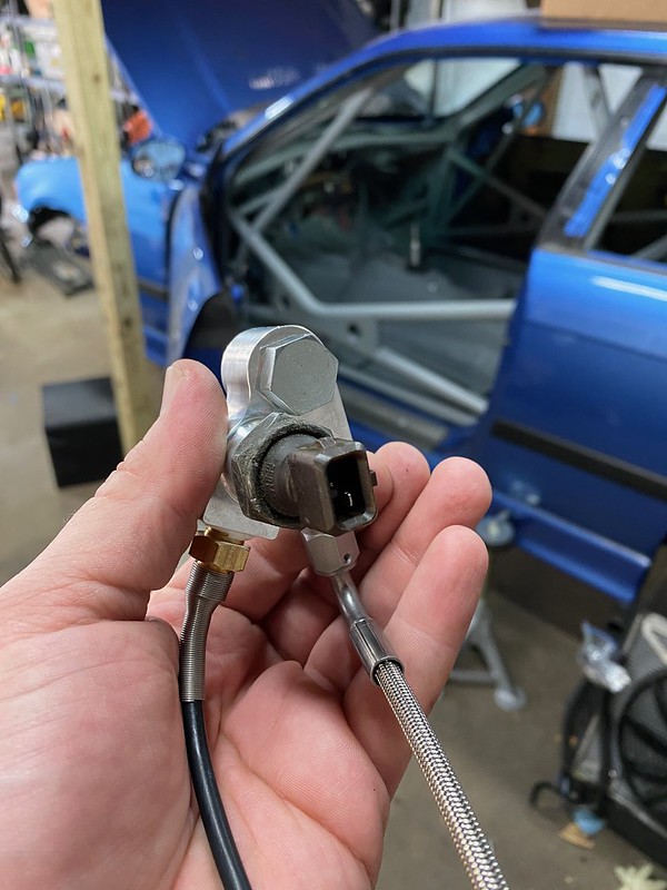
While the manifold was off, I also installed a water temp sender into the port where the throttle body coolant hoses went, and an oil distribution block for oil temp/pressure. Easy enough to do. At this point, all of the engine items are done. If I end up going IP, the head will come off for cams and other hardware. If I end up going IS, I will have to take the manifold and headers off.
I was cruising eBay one day and spotted a killer deal for a set of TCKline camber plates. I was saving for a set of Vorshlags but I got these at 50% off so I am not complaining. I will upgrade to the Vorshlags if/when I get a set of high-end dampers. Out they came, and back in they went.
IMG_7093 by Scott Stirling, on Flickr
IMG_7092 by Scott Stirling, on Flickr
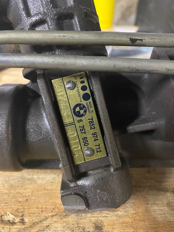
Another item I scored a good deal on was a Yellow Tag steering back. No pictures install pictures here. The hardest part was getting the steering shaft back it but overall, the install was pretty easy. While I was in there I replaced all the steering fluid lines and replaced the steering shaft join with a new OEM piece.
Since the car didnt start at this point, I had to improvise on how to prime the steering system.
Next, I turned my attention to the rear of the car to install the diff I purchased, as well as the new rear shock mounts and the exhaust system. With COVID running wild in Bergen County, I would have to tackle all of this myself. Shock mounts, not really much to talk about here. A few bolts and out they came, a few more and back in they went; kind of. On re-install, I stripped the trailing arm thread for the lower shock bolt. I have a Helicoil to fix it but just havent gotten around to it. Not overly concerned, just one more thing to do.
One item I will point out is to make sure you order the correct diameter spacers for your brand of shocks. I ordered the 12mm set but I meant to order the 10mm. BW will sell you the spacers as a standalone item so now I have a spare set if I upgrade to a shock with a different diameter.
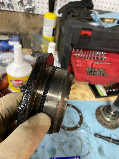
When I purchased the new diff, the prior owned mentioned the output flange seals might need to be replaced. As preemptive maintenance, I took the time to replace them. Pretty easy and straight forward job. Drain the fluid (which looked brand new), undo some bolts, change some o-rings, a seal and a snap ring, and bolt it all back up.
Got the stock diff out by myself just balancing it on a jack.
Getting the new one back in was a bit harder. Thankfully, my fiancé was gracious enough to captain the jack while I guided it from under the car. After getting it pretty close, I had to strong man it up and into the subframe. Was terrified about dropping it but thankfully did not. Sorry, no pictures here.
With most of the heat shielding removed I was concerned about the heat from the exhaust warming the fuel tank. As such, I covered most of it in the gold foil fabric that BimmerWorld sells. Same stuff I covered the engine mount in. No idea how well this work, and I have no way of telling since I am not tracking fuel temps, but I trust BW to sell quality products. Picture is not the best but hope this gives you an idea. Also installed the remaining fabric around the muffler area on the rear; no pictures.
I'll stop here for part 1 of this update. Will try to post part 2 later today.
Member
Great update!
Let us know how those TCK camber plates work. I always wondered about those.
Member
I will kick off part two with a generally pictureless update. After I got the diff in, I took a stab at installing the exhaust. While this should have been easy and straight forward, I naturally made it harder than it needed to be. To start, because I was using the euro-style exhaust, I needed euro style gaskets between the headers and mid-pipe. This is a euro-only part that does not have any cross over to US cars. The main reason this exhaust was not installed sooner was because it took ECS 6 months to get me the gaskets. By I time I got them, we were deep into track season and I never had time to do the install. Well low and behold when I went to grab them for this install, they were nowhere to be found. Keen on never giving ECS a dime of my money again, a friend found me some MLS gaskets that were only a MM of the ID spec I needed. I drilled some new holes in them and we were good to go.
Unfortunately, I realized during the test fit process that the washers SuperSprint supplied with the mid-pipe do not sit flush on the exhaust. The outside of the washer comes into contact with the weld bead between the flange and the exhaust pipe. Dremel makes work of them albeit a timelessly process since the washers are hardened SS. I had to remove about double the length and wide of the indent from each washer to get them to sit flush.
After this small delay, the mid-pipe mounted without issues other than the fact I broke the ceramic gasket on the muffler side of the mid-pipe and had to source a new one. Thankfully this is shared with the E46 M3. The only other issue I ran into was replacing the muffler hangers. I purchased new H J Schulte branded hangers from FCP, and the bolts they supplied were too short to mount. Only one thread engaged. I typically would have let them know but I was under a deadline and just got new hardware from ACE.
As some point in the above, I installed all new ABS sensors in the car.
At this point, the rear is done; sans Helicoil. I then went back to the front of the car to built a radiator baffle. I had created a separate thread on this with the idea of building an overly complex thing that perfectly directed air to the oil and PS coolers I ended up not upgrading too/purchasing. A number of you (correctly) convinced me to keep it simple; so that is what I did. This is made of thin gauge aluminum, bent from a single piece, and cut to fit the area. I used aluminum tape to seal it to the euro oil cooler and patch up some excess spaces. I secured it to the chasses with some coarse screws that initially held in the stock baffling.
This is the first time the front bumper has been on in almost two years. I had a giant smile on my face when I took this picture.
Happy with how this turned out, I started to fill the cooling system with water, only to find out that I had punctured the radiator at one point. Quick order from FCP and I had a new one in less than 24 hours.
During all of this work, I was also finishing the wiring of the car. I will write a separate post on that but while I was plugging away, and waiting almost a month to get my tune, I started to install my safety systems. The seat is an OMP HRE XL, harness and center nets are Schroth. I have to say, I have never had Schroth harnesses before but I wont be buying anything else again. These are so much easier to work with and adjust.
- - - Updated - - -
Absolutely. Thus far, I am happy with them but have nothing to compare them to. From my research, people seem to wear the bearings out quickly so I will be keeping an eye on that.
Member
Yea, there IS a difference between a $200 harness and a $500 harness. I've owned one Schroth setup, and it just felt SOOOO smooth and easy to adjust. It makes a big difference when it's 100 deg and you're sitting in the paddock rushing to get strapped in.
Member
One thing I am happy with the result of is the door and door pulls. If you recall, I thought that cutting up the door was a waste of time when you compare it to the amount of effort needed to cut them out and the amount of weight saved. One thing I HATED was how rough the edges were, even after sanding. I was browsing for an edge guard to use and was unable to find anything locally. What I did find is this awesome flame-retardant plastic trim from McMaster (Part Number 24175K61). It has a thin, pliable metal core, coated in rubber, with a lip on the inside to prevent it from slipping off. Highly recommend.
For door pulls, I used 3/8 inch, coated wire rope, and SS clamps. I mounted it with an eye-bolt and some nylon insert nuts on one side. On the other side, I bent the OEM door wire on to form a loop to connect to. I have not done it yet but I plan to move the driver side mounting point up to just below the window triangle that sticks up on the door. The passenger side is like this and I like how it holds the wire higher up. As its mounted in the pictures, the wire is in line with my door bars and I dont want to have to panic-search for it in an emergency. I stole the idea for the orange door pulls from aeronaut; thanks again for the idea.
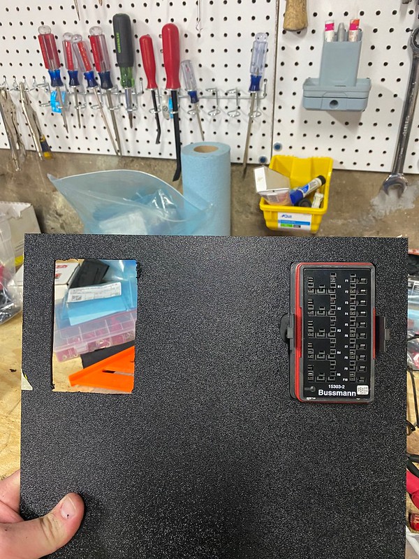
The last time I posted about wiring, I had decided to move the entire fuse box into the main cabin. I ended up with two fuses boxes; both Bussmann RTMRs, but in different configurations.
The first box I purchased is a 15305-2-2-4. It allows for 5 Micro Relays and 10 mini fuses; both sides are bussed internally. This box will hold the relays for my lighting, puller fan, secondary fuel pump, and other accessories.
Since both sides are bussed, it presented me with a great way to clean up the power and ground sides of the wiring for these items. In a typical setup, the relay would receive power via the internal bus; and then you would run your wire to an inline fuse and then on to your accessories. Since I already had a side of fuses receiving power, I instead leveraged the internal bus on the relay size as a ground bus. With the micro-relays, this is as simple as running the relays upside down and installing a jumper wire from the powered fuses to where the 30 pin would sit when installed upside down. Here is a picture with the jumpers installed. Again, highly recommend this thread if you want to learn more about what I did here.
https://www.tacomaworld.com/threads/...-block.399454/
The second box I purchased is a 15303-6-2-4. It holds either 3 mini relays or 5 micro relays on one side, and 10 mini fuses on the other. On this one, only the relay side is bussed. The reason I picked up a second box was that I needed several fuses for items that were already receiving power from another area (main fuel pump etc). Additionally, there were several items that I wanted to be powered on the ignition and I was unable to wire it properly if the entire fuse block was bussed. As far as the relay side, Eaton does not sell a version of this that is 20 fuses, one side bussed, one side non-bussed. So I picked a bussed relay side and am using it as my ABS fuse power. Each bus can take up to 80 amps, and with no plan to use this side of the box, it seemed like a good idea to put these two high amperage items on a separate bus.
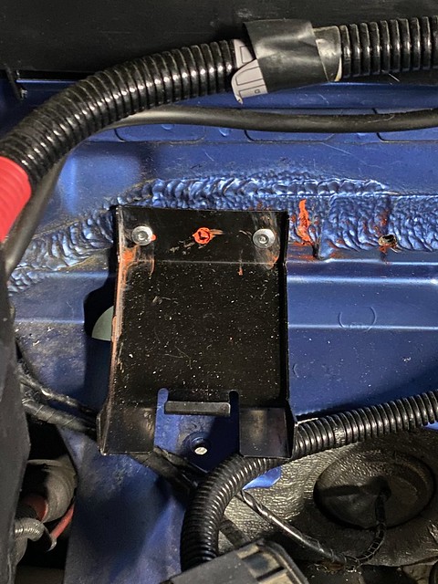
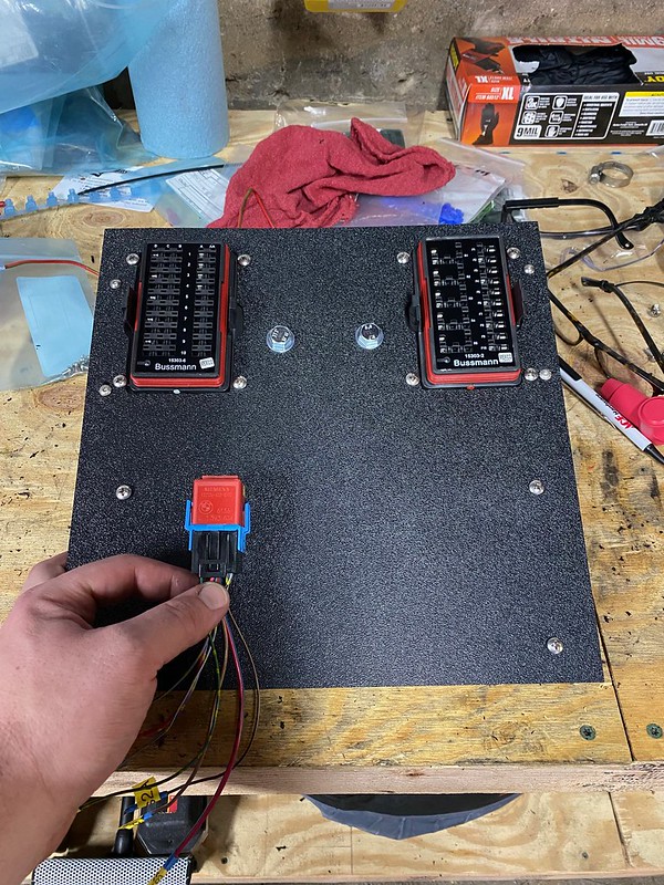
Other items I purchased were the BimmerWorld master kill solenoid and 4 Blue Sea mini busbars. To mount everything, I purchased a 12x12 panel of ABS plastic off amazon and a Longacre panel bracket. The goal with this panel was to hold all wiring related items: fuse boxes, master solenoid, external relays, and busbars. I started by marking where I wanted to fuse boxes to go and then used a Dremel to cut the appropriate size holes.
Given the size and weight of the master solenoid, I wanted it to be mounted close to the mounting brackets of the panel and decided between the two fuse boxes would work best. Mounting was very simple, drilled some holes, and attached with bolts. I also mounted the busbars with some basic hardware.
A quick test fit made me realize that the master solenoid interfered with my dashbar. I decided to mount it to the front of the panel and cut an access hole for the wiring.
The reason I wanted the solenoid close to the rest of the wiring was to leverage the open power terminals where the battery cable connects. These serve as a tap point for several wire leads without having to further cut up the battery cable. Here is the panel with the power wires. In addition to the battery cable running to the solenoid, I have a 3, 10 AWG wires connected to a ring terminal that supplies power to two of the internal busbars on the fuse box and a separate bus bar I can tap into for power. The second bus bar you see on the left is for my grounds. I ended up having to add a second ground busbar after this picture was taken.

Member
Here's a pretty well done video of a bussman build for a race car https://www.youtube.com/watch?v=p6CU9Dsw_R0
I was planning to do this as well, but now the dream is to try an AIM PDM8/32 if they ever become available
Member
Thank you! that guy did a great job. My end product is not nearly as clean.
Hear you on the PDM. for me MoTec everything is the goal. One day... in the far away future. I hope.
Member
Hey everyone, I have more updates to post but am lacking motivation to upload pictures and type it all out. Essentially, the car is done. Aside from the headers and M50 manifold, which i'll address in a second, I am only a rain light away from going out and racing CCA IS class tomorrow.
There has been a lot going on in the background and I have unfortunately come to the conclusion that any track days this year is unlikely and that IP class is unattainable for at least the next 18 months. So this is now going back to an IS build. Thankfully, that is straight forward; I just need to remove the headers and the m50 manifold. The only issue is that I need to find a way to bridge the stock headers to my mid pipe. No one sells anything off the shelf so I will have to have something build, or I can sell the full system in favor of the BW exhaust, which is what I am doing.
If anyone is interested, the full SuperSpring race exhaust is listed here:
https://www.bimmerforums.com/forum/s...4#post30524324
Member
It's been a while, let's get this thread rolling again. I am gonna start this off again going through pictures I have and will probably going to miss or skip over a few things. If anyone has any specific question, please ask!
Fire system - As much as I wanted a novec system, COVID fucked my budget for this year so I ended up going with a foam system. Specifically, I went with the Lifeline Zero 2000 Fire Marshal 4.0 ltr Steel Fire Suppression System.
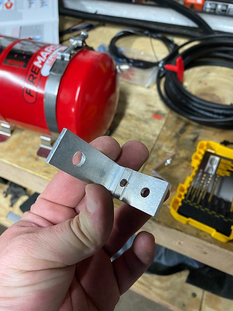
To mount the nozzles, I make these little brackets out of some 90* aluminum I had laying around. Just drilled some holes and then used rivets to secure them.
For placement, I went with two on the driver and two in the engine bay. I only used four as I wanted to maximum the amount of time the fire system would continue to spray. A reminder, the point of a fire system is to suppress the fire enough for you to bring the car to a stop and GTFO. That is why it's called a Suppression System, not an Extinguisher System.
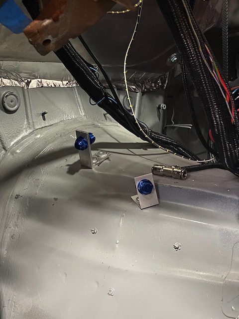
For the driver nozzles, I wanted one at my feet and one at my legs and lower torso. Ignore how the picture makes it look like the closer nozzle looks like its point down, I have since bend it back so it points up more. Generally, I am happy with this placement for now but might move one nozzle to the steering column so it better gets my lower torso. NOTE - the direction specifically say NOT to have it spraying at your face, please keep that in mind when installing.
For the engine bay, I wanted one pointed at the headers and one at the coils. The one pointed at the coils also will coat the top of the engine and intake manifold. Simple enough.
To cut all the tube, I used a simple pipe cutter. Had to be careful to not crush the metal liner in the tubing though, its rather delicate. Running it was simple enough, lay it out and bend lightly to match the profile of where you want it to go.
Fire bottle mounts with some simple nuts and bolts. You can see the pull handle locations in a post I am going to make shortly; one is located just to the right of the shifter, and the other just next to my passenger side

 Posting Permissions


 Reply With Quote
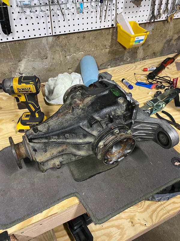


Bookmarks