
 Member
Wowzah!
1000+RWHP, Lab22 Built Turbo S54 - BMW Half Mile Record Holder
u owe my mule an apology
subbed for plasma cutter pics! This is going to get exciting!
86 325es, 2.8L m50, S476sxe, ProEFI 128 ecu, e85, solid rear axle, TH400 trans, 28x10.5w slicks, zip ties, popsicle sticks, tape
best time 9.06 @ 151.8 mph, best 60 foot 1.30
M54B30 Inside
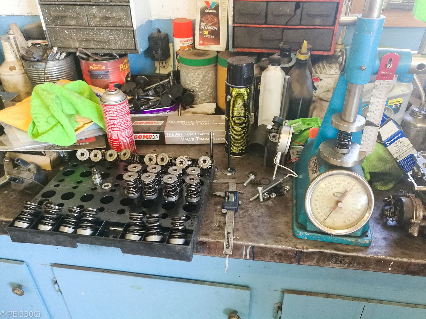
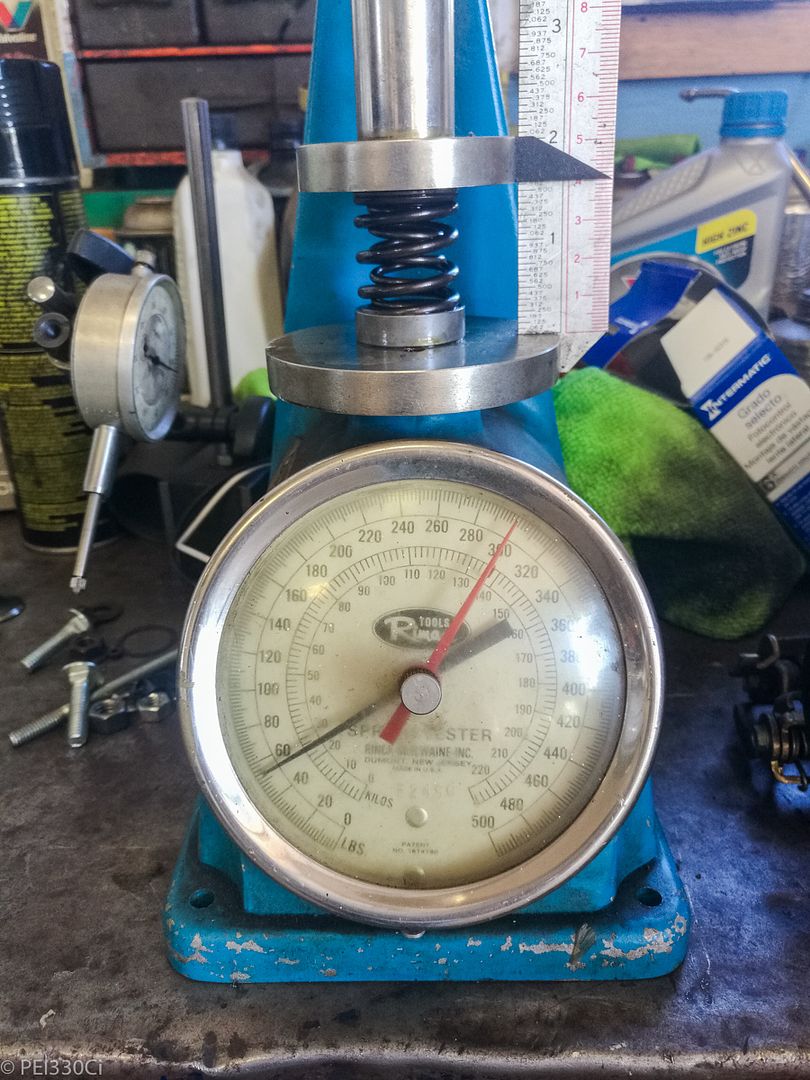
Has anyone ever tested their valve springs?
What you're looking at above are the valve springs being compressed to the installed height. This is known as "seat pressure". I found that with intake valves, the seat pressure was around 52-54 Lbs, and with the exhaust valves (which are about 1mm shorter) the seat pressure was 60-62 Lbs
M54B30 Inside
Using a value of 10.9mm of lift on the Intake, I found the open pressure of all the springs to be 148 to 150 Lbs.
Using a value of 10.5mm of lift for the Exhaust, I found the open pressure of all the springs to be 154 to 158 Lbs.
I believe many years ago I tested some OEM M54 springs, and some Behive springs from Metric Mechanic....but I can't recall where I documented that. I'm looking at taking apart a stock head that I have in the shop, and testing what the OEM M54 valve springs do as well.
I don't know that this is an issue, but the advertised "seat pressure" of Supertech and also Ferrea are much higher. Both of them offer a spring package rated at 80 Lbs of seat pressure, and Supertech has a package rated at 94 Lbs of seat pressure.
I'm not a valve train expert, so I'm looking to get some professional advice on this situation.
u owe my mule an apology
There is a thread on here from years and years ago where someone tested a bunch of stock valve springs, m50nv, m50, m52, s52, ect... They tested them all from 2" though so you have to know the installed height and do some math to make any sense of it. The m50nv ones they didn't test with the lower spring perch inside the inner spring so they are off as well. I can't remember what the installed height is on the M50 and M50nv, I don't think I ever wrote it down. I have a spare NV head on the shelf I can measure but I think its slightly different from the vanos installed height.
86 325es, 2.8L m50, S476sxe, ProEFI 128 ecu, e85, solid rear axle, TH400 trans, 28x10.5w slicks, zip ties, popsicle sticks, tape
best time 9.06 @ 151.8 mph, best 60 foot 1.30
M54B30 Inside
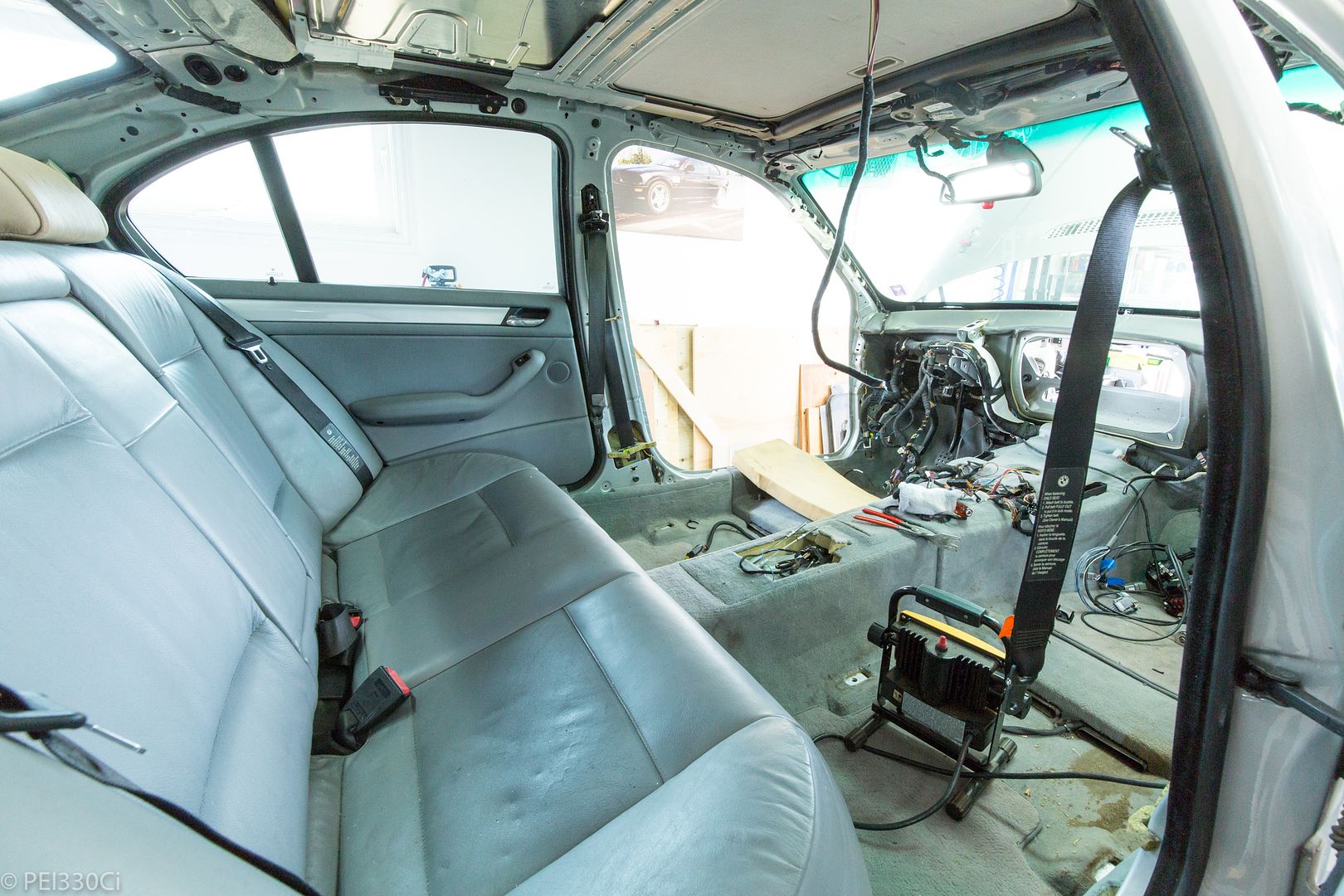
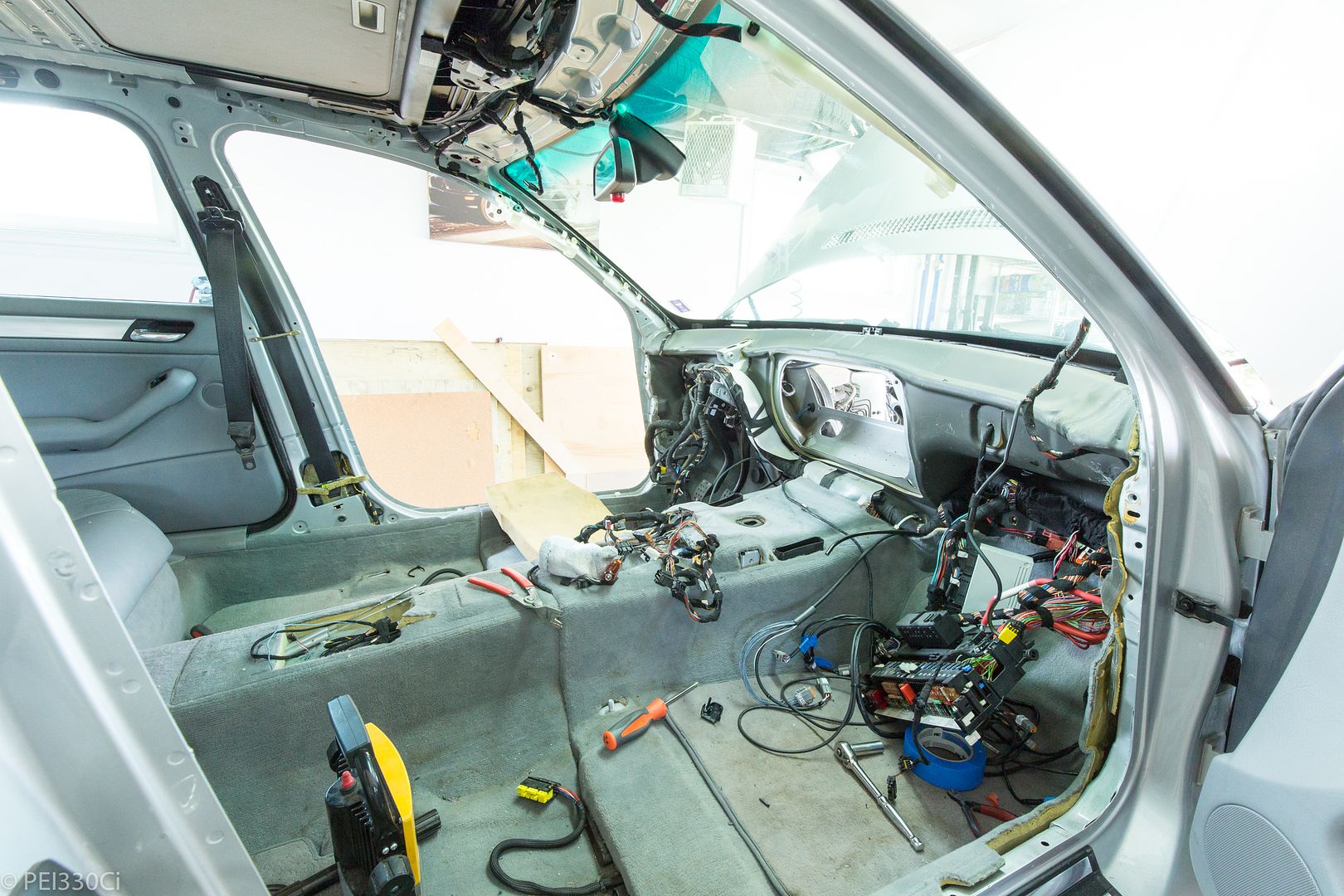
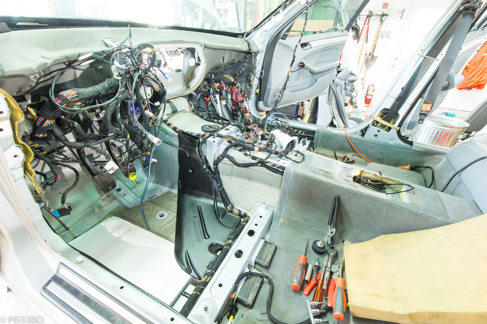
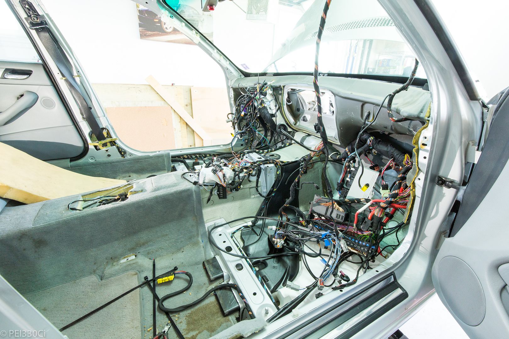
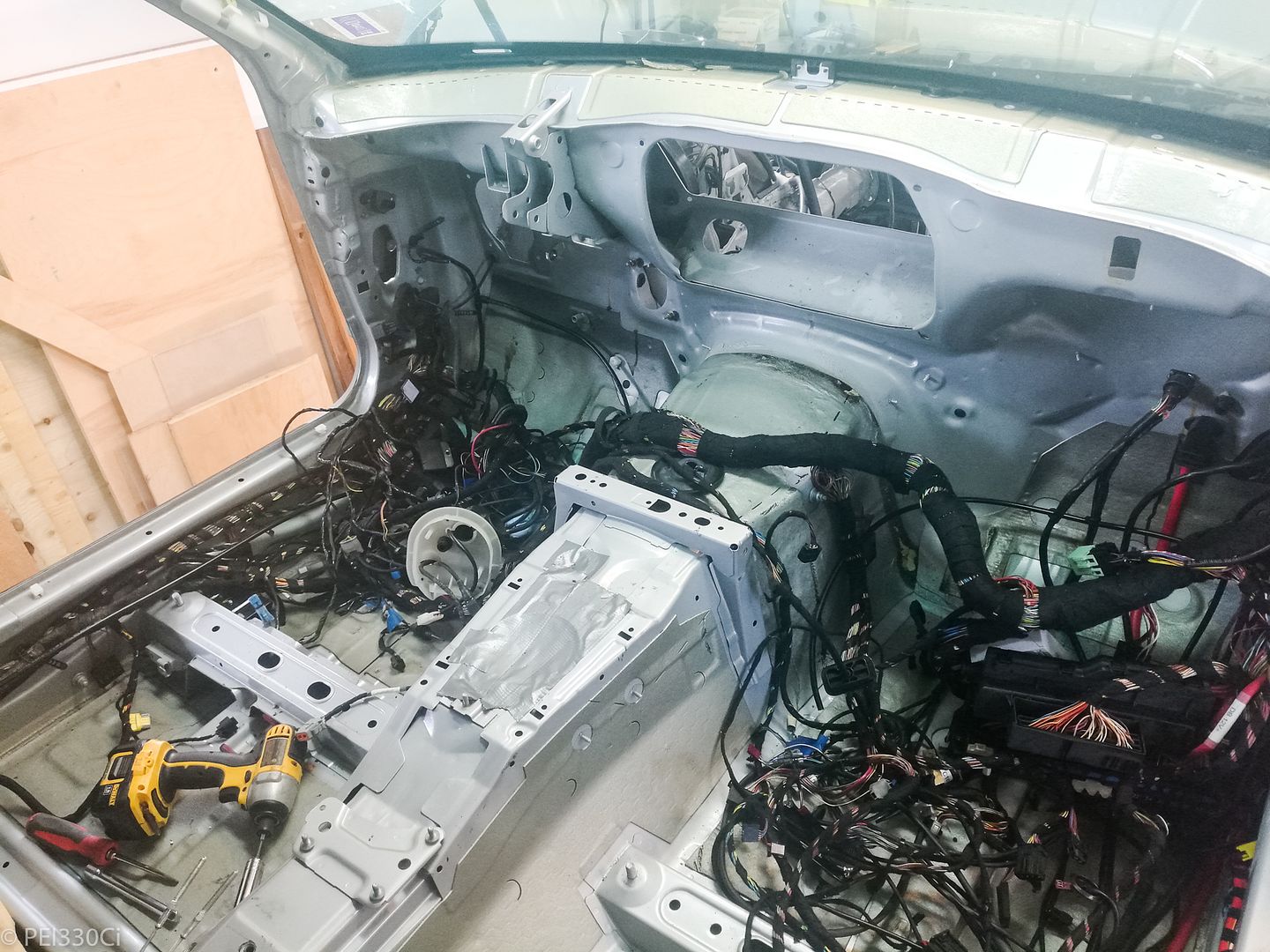
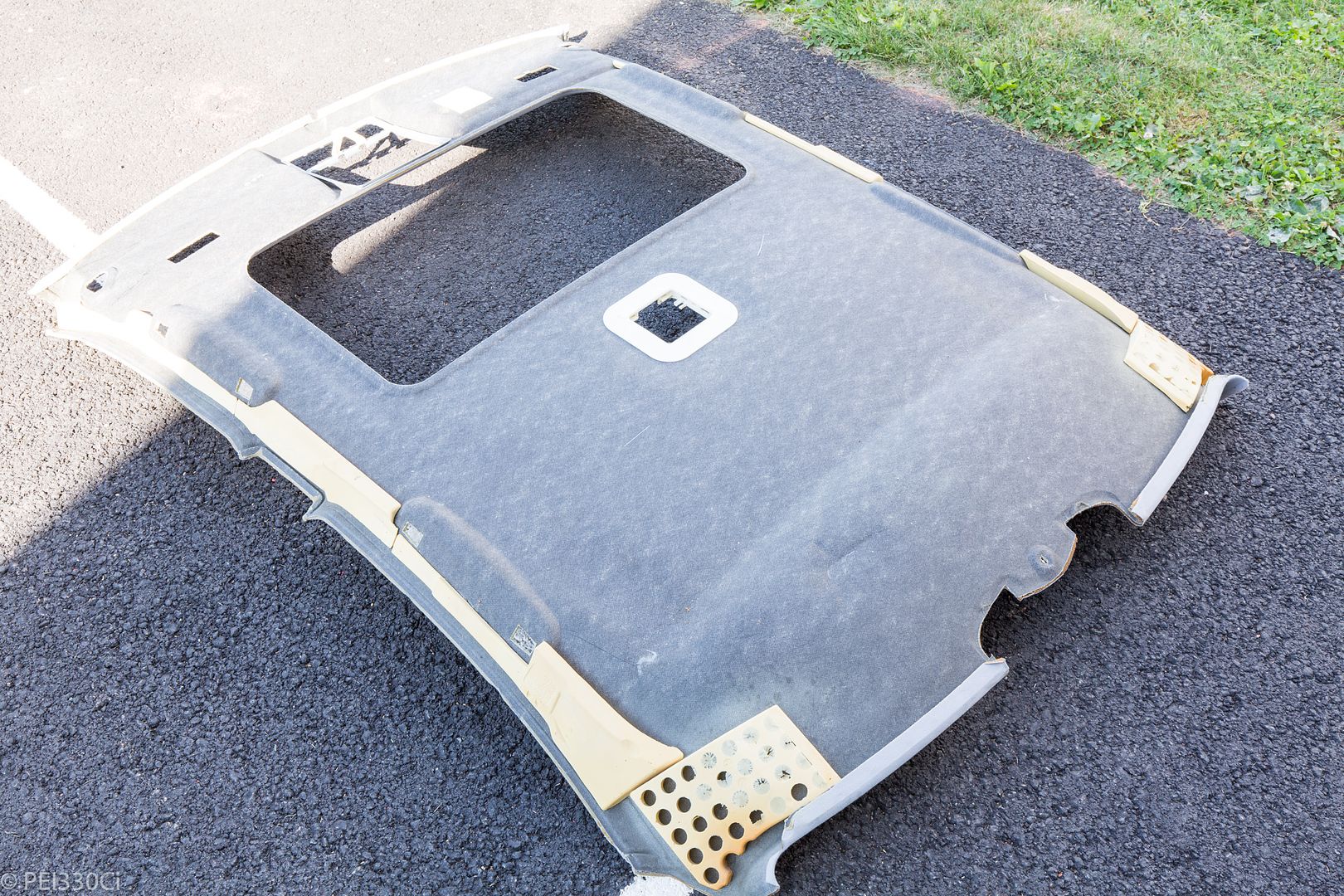
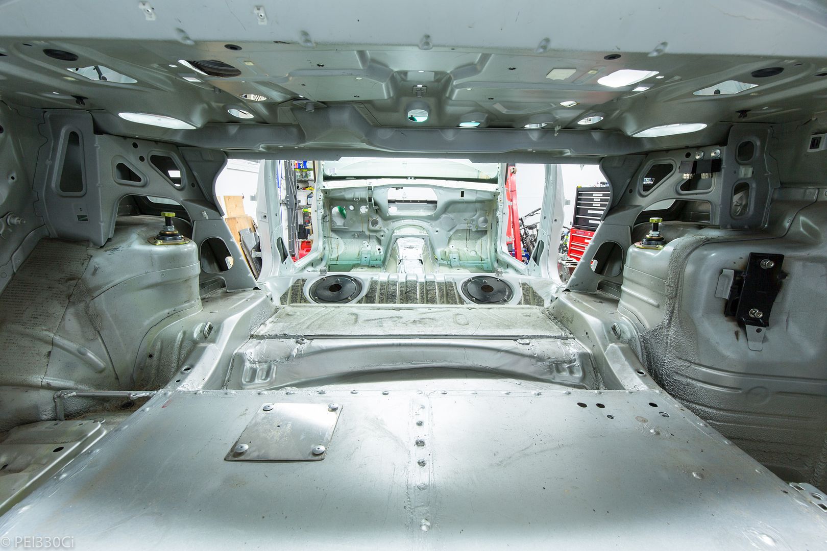
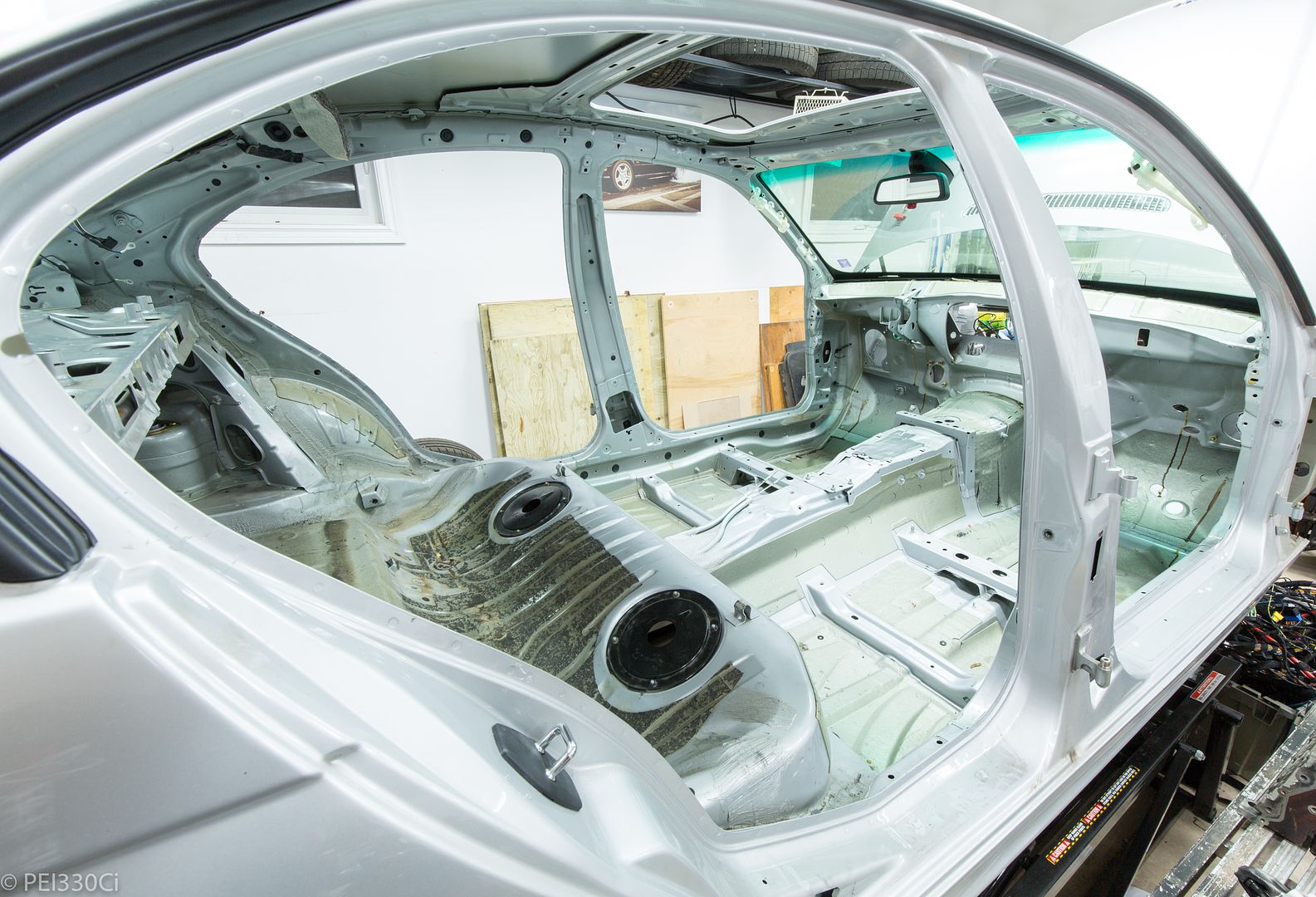
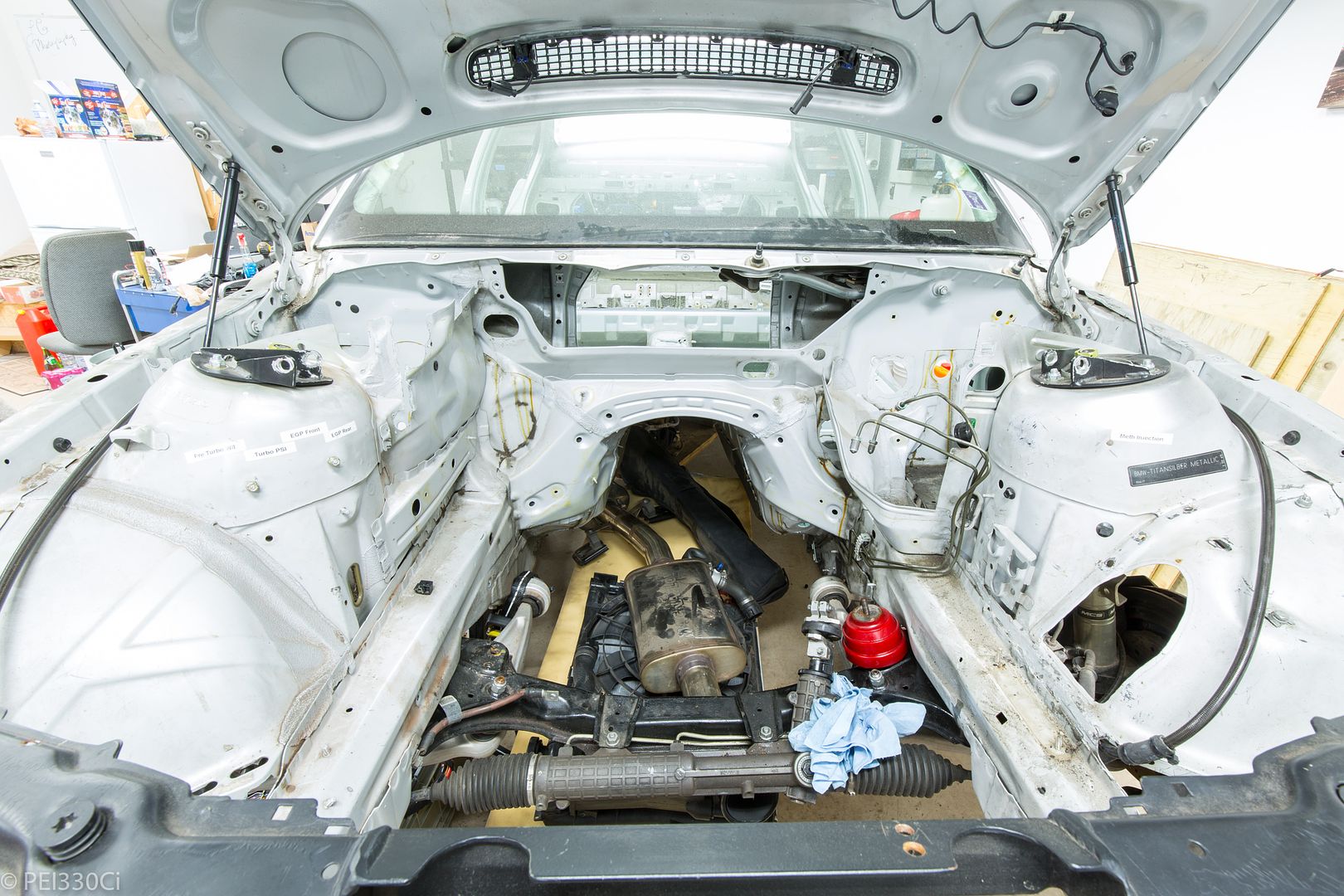
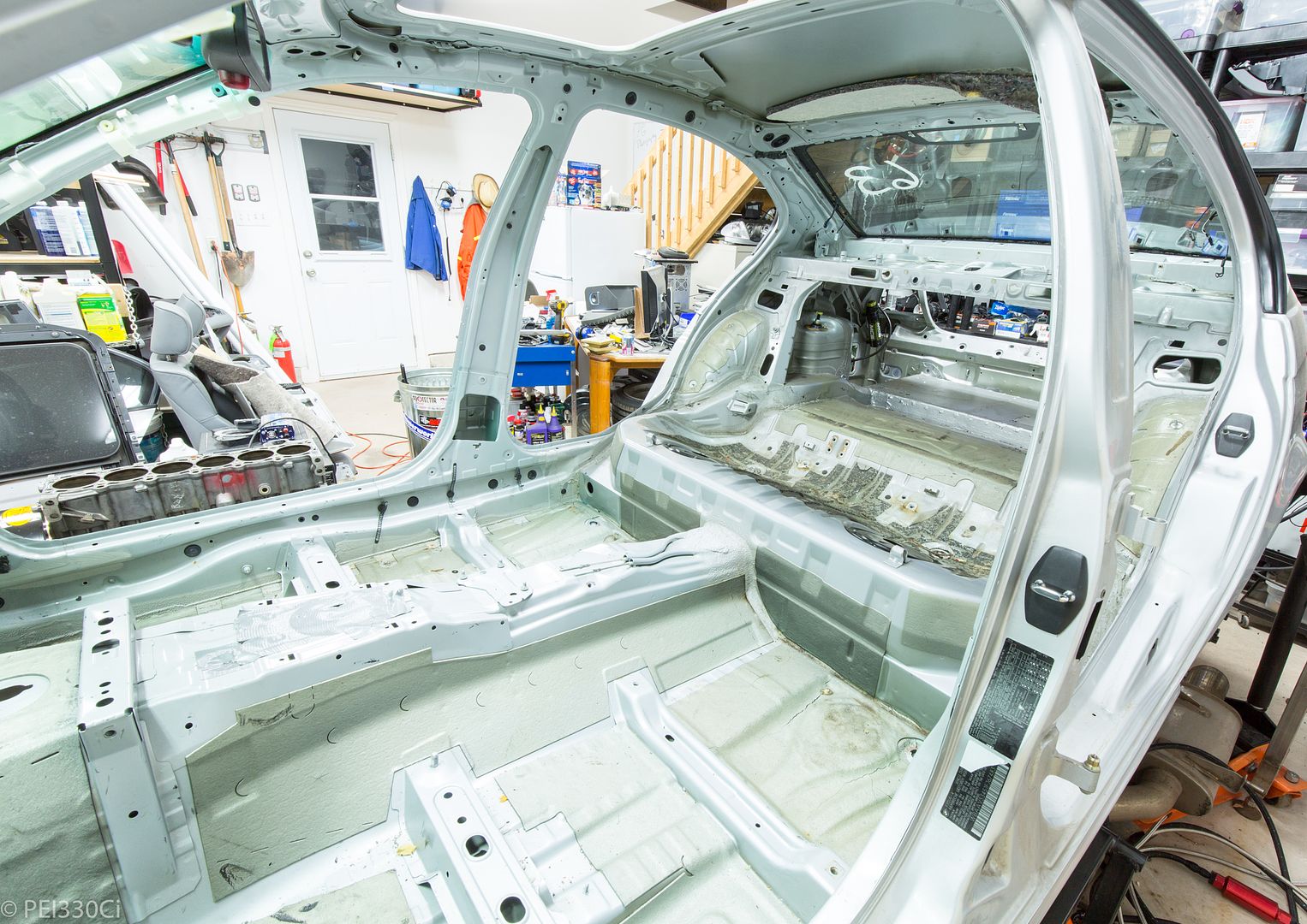
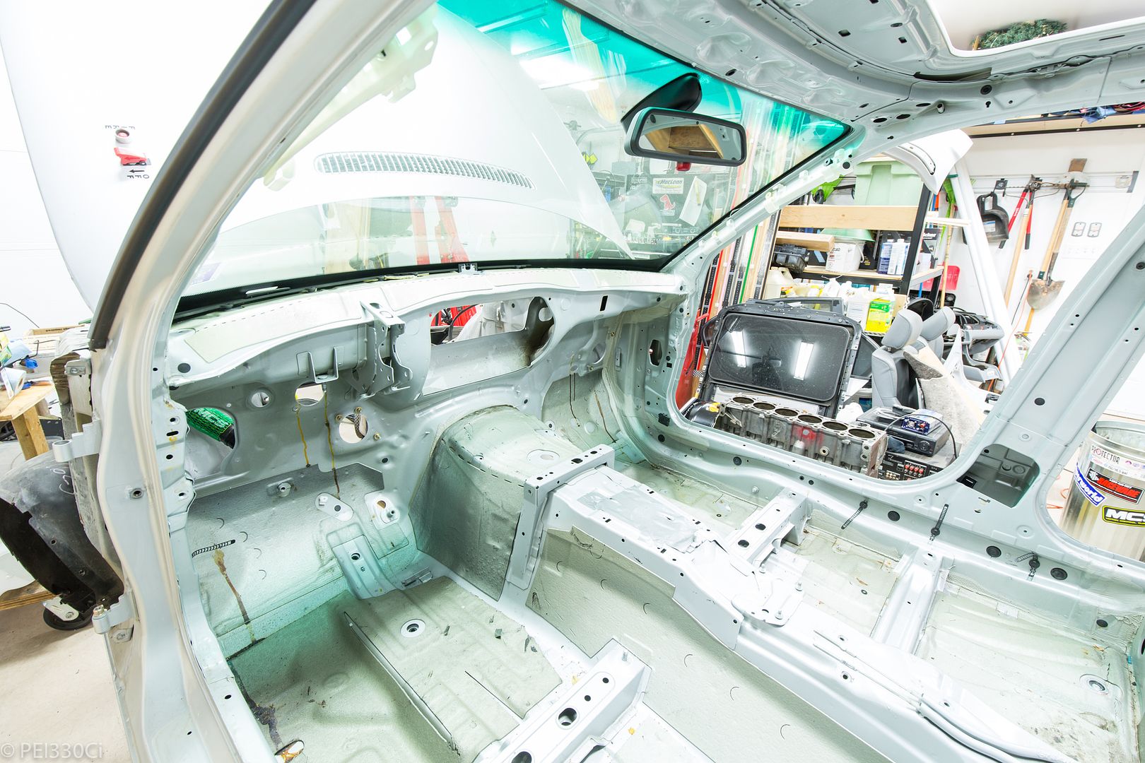
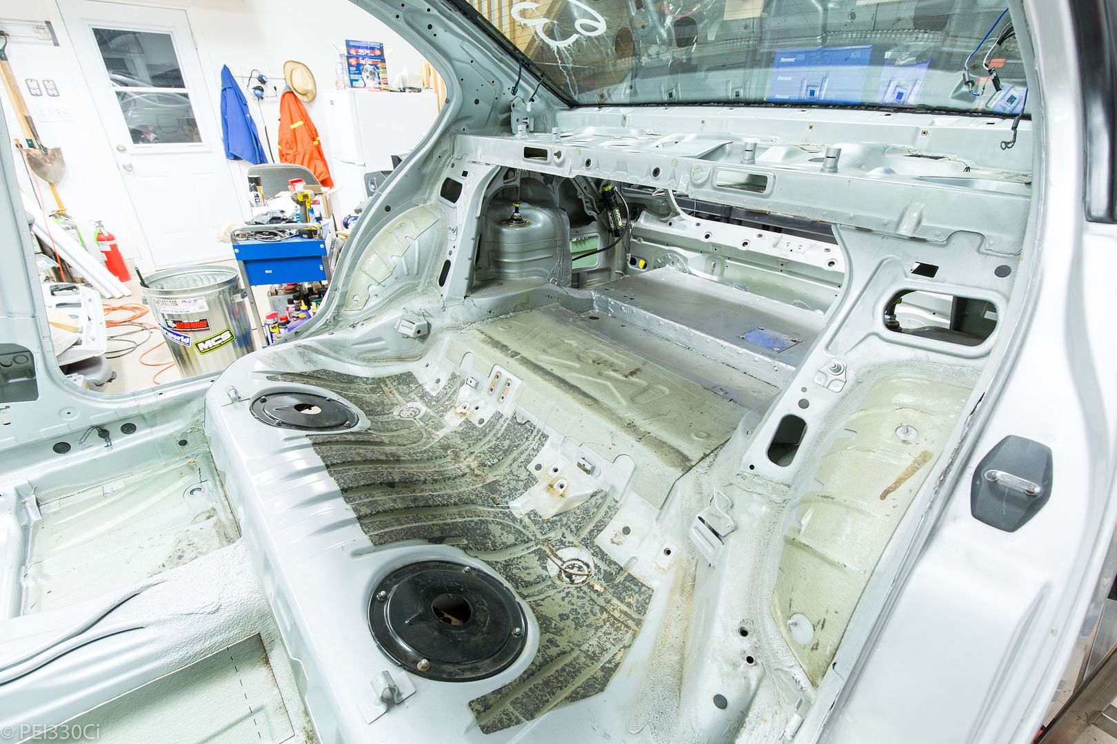
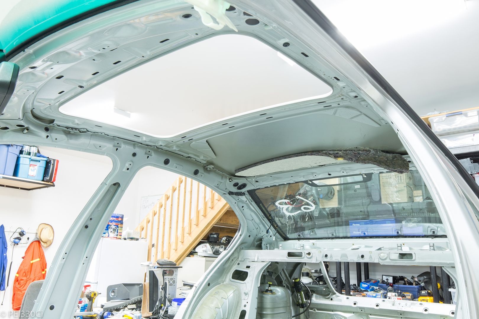
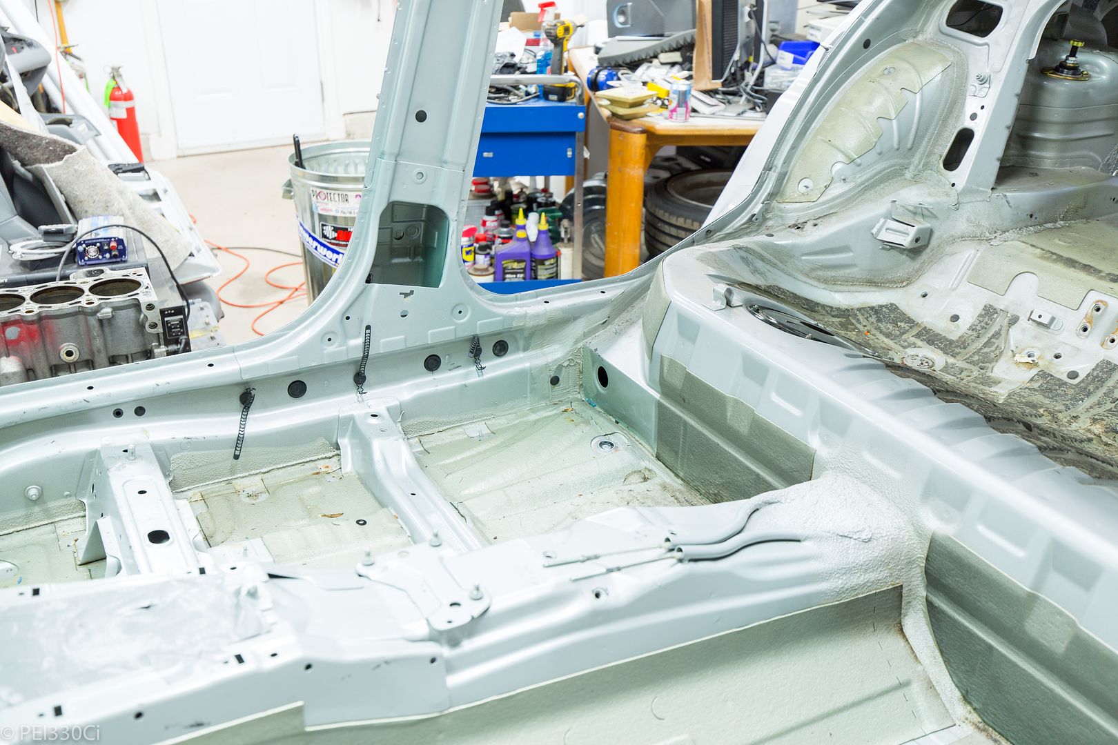
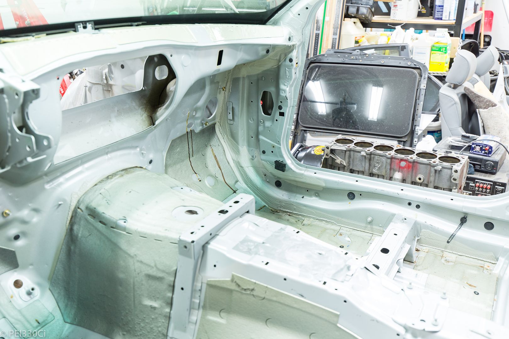
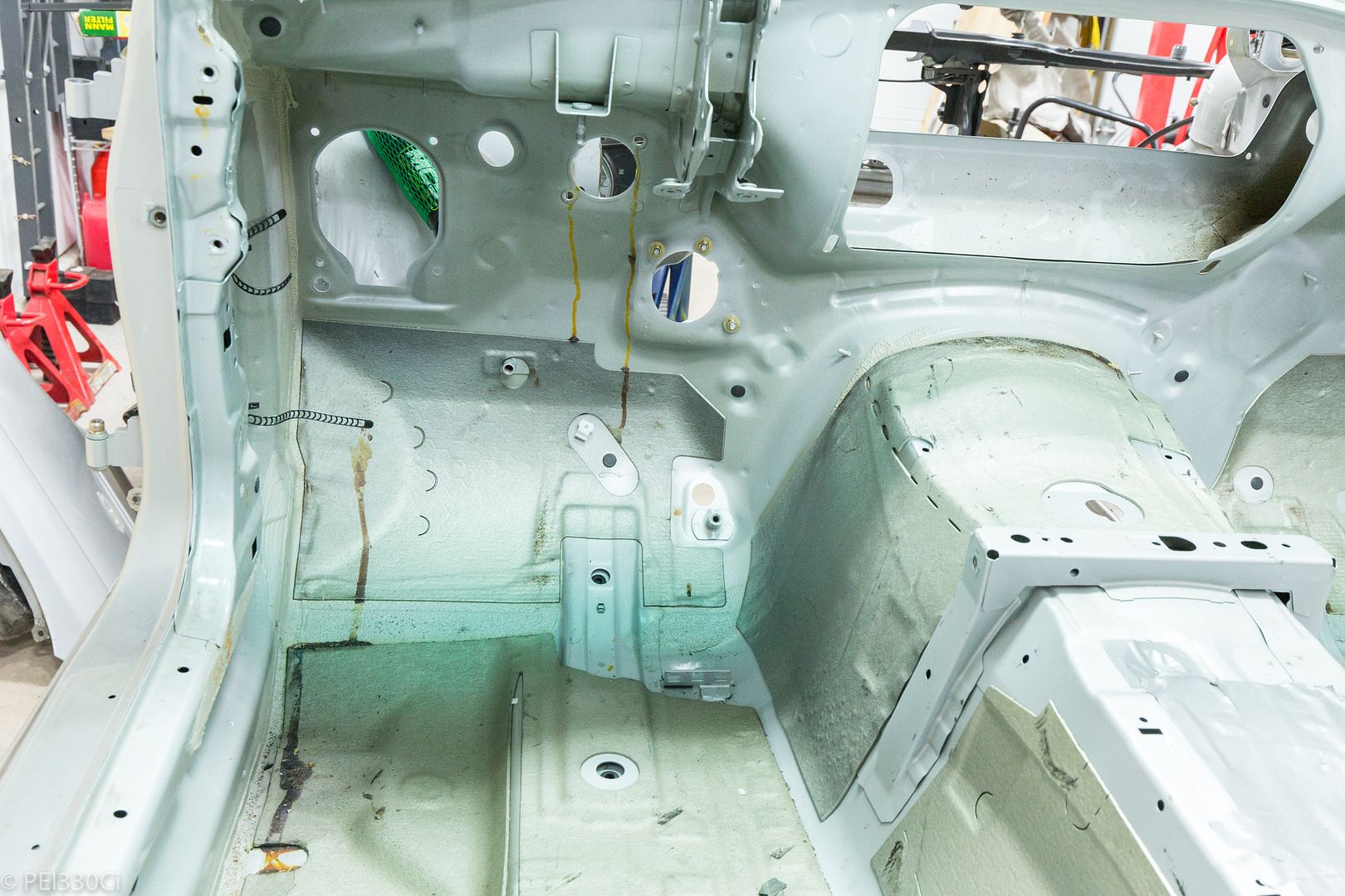
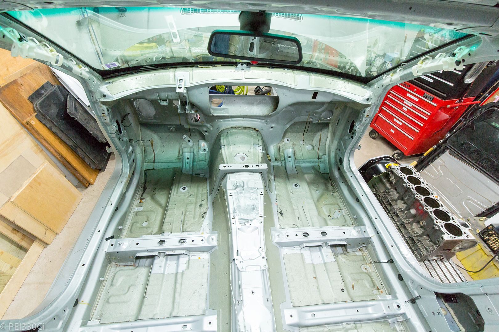
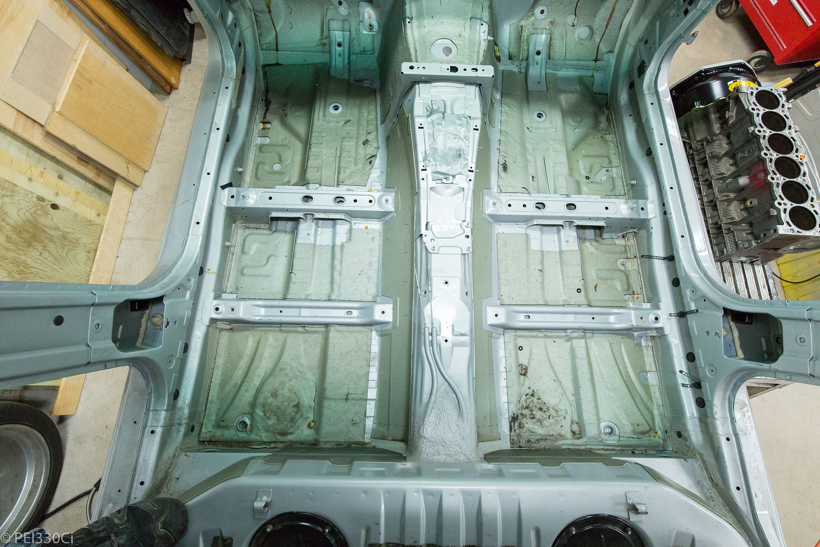
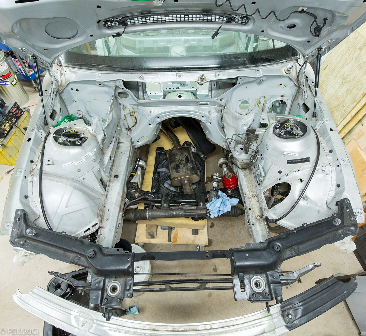
The process of gutting the car:
- - - Updated - - -
What I'm most interested in is the seat pressure for the valves. We all seem to be using the same 33mm intake, and 30mm exhaust valves, with lifter buckets that are about the same mass. The engine speed and camshaft profile is going to want a specific spring package, but there is VERY little documentation on this. In contrast, the SBC crowd talks about spring pressures the way we like to chat about boost pressure.....Originally Posted by someguy2800

- - - Updated - - -
The gutted car:
- - - Updated - - -
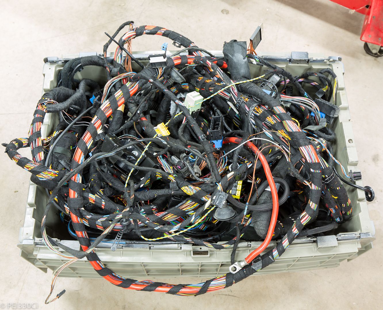
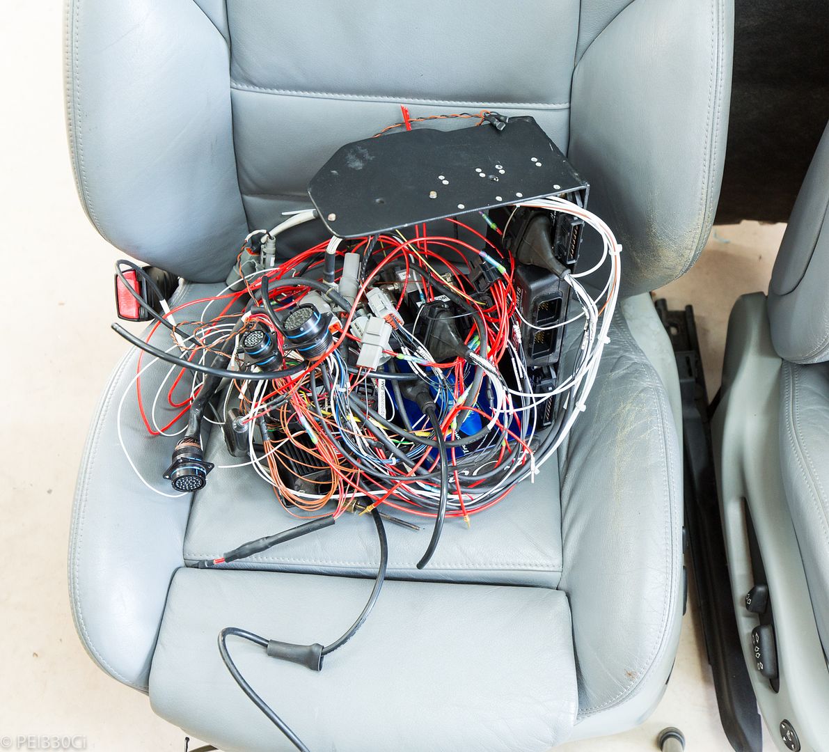
50+ Lbs of wiring that came out:
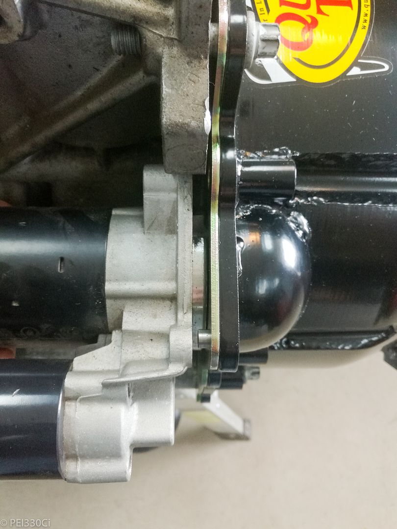
Starter doesn't fit into Quick Time Bell Housing:
I contacted a vendor to measure other starters they have in stock, and they are actually deeper than the one that I have making the problem worse. I'm going to contact Quick Time about their mistake....in the meantime I'm going to have mine modified.
Wasn't too impressed with how the starter cover isn't fully welded:
M54B30 Inside
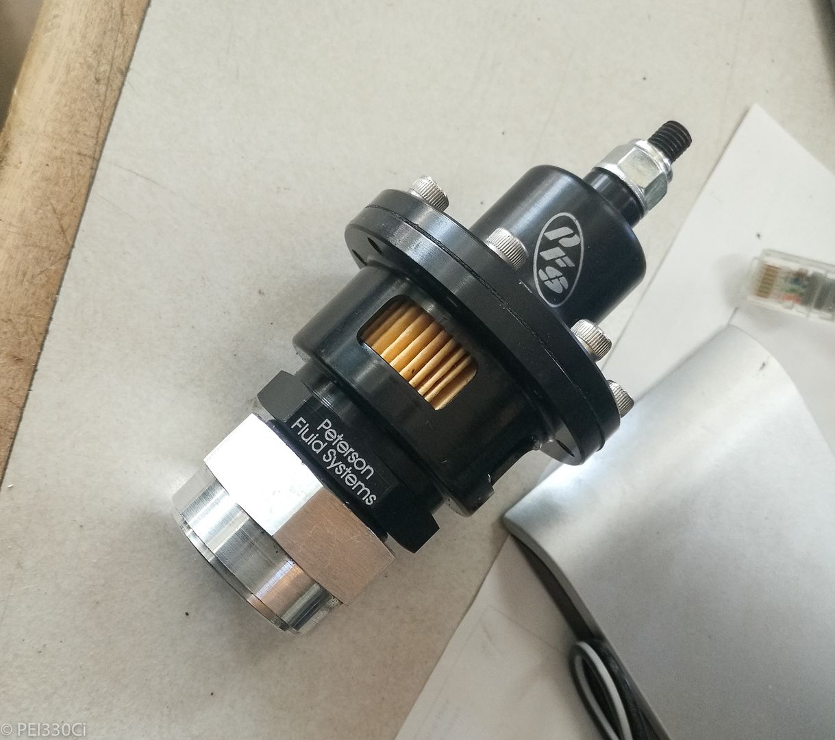
Vacuum Regulator for Dry Sump system:
This sucker took 4 months from the time I ordered it from Jegs (Listed as In Stock), to when I received it. I'm told it's no longer in production?
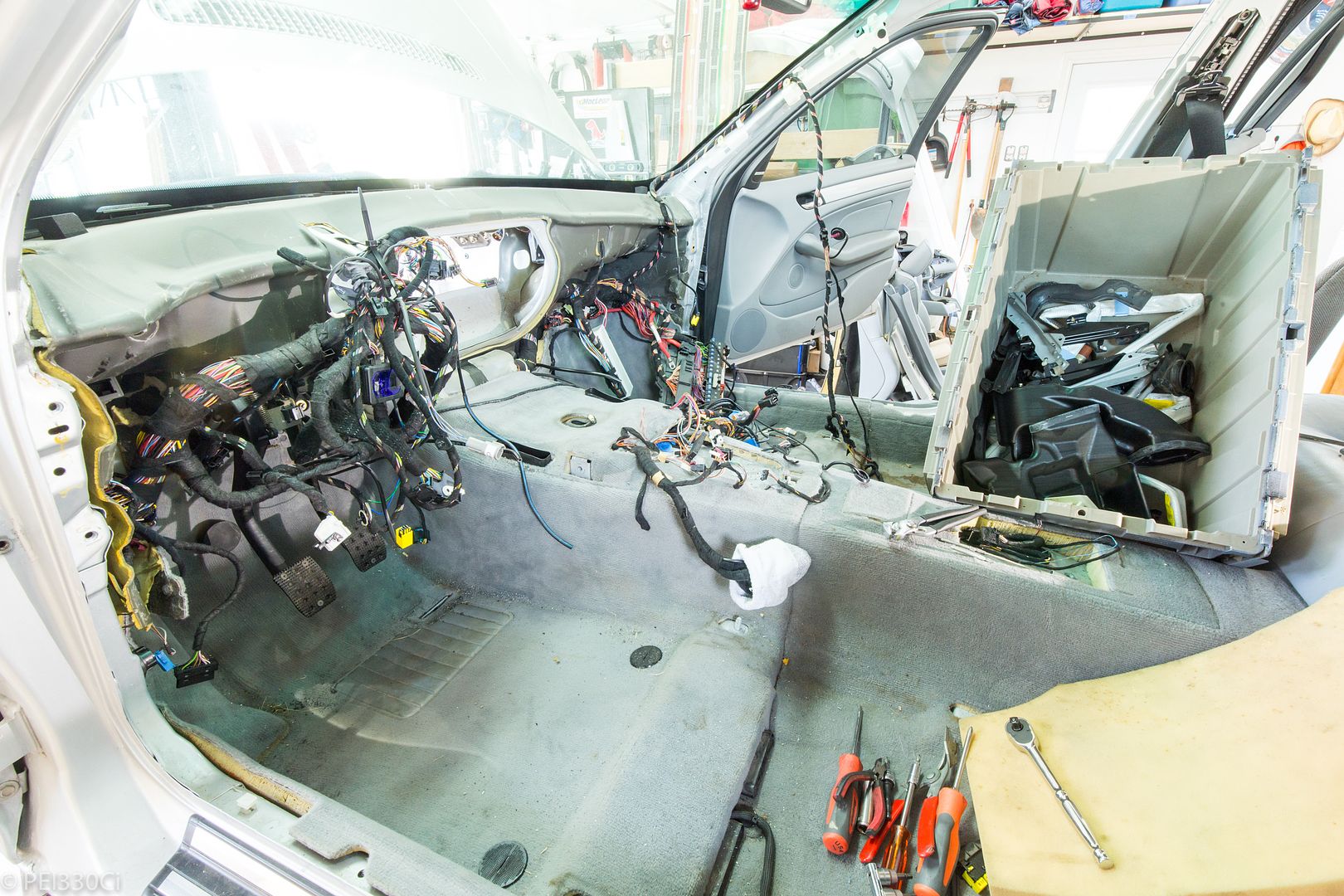
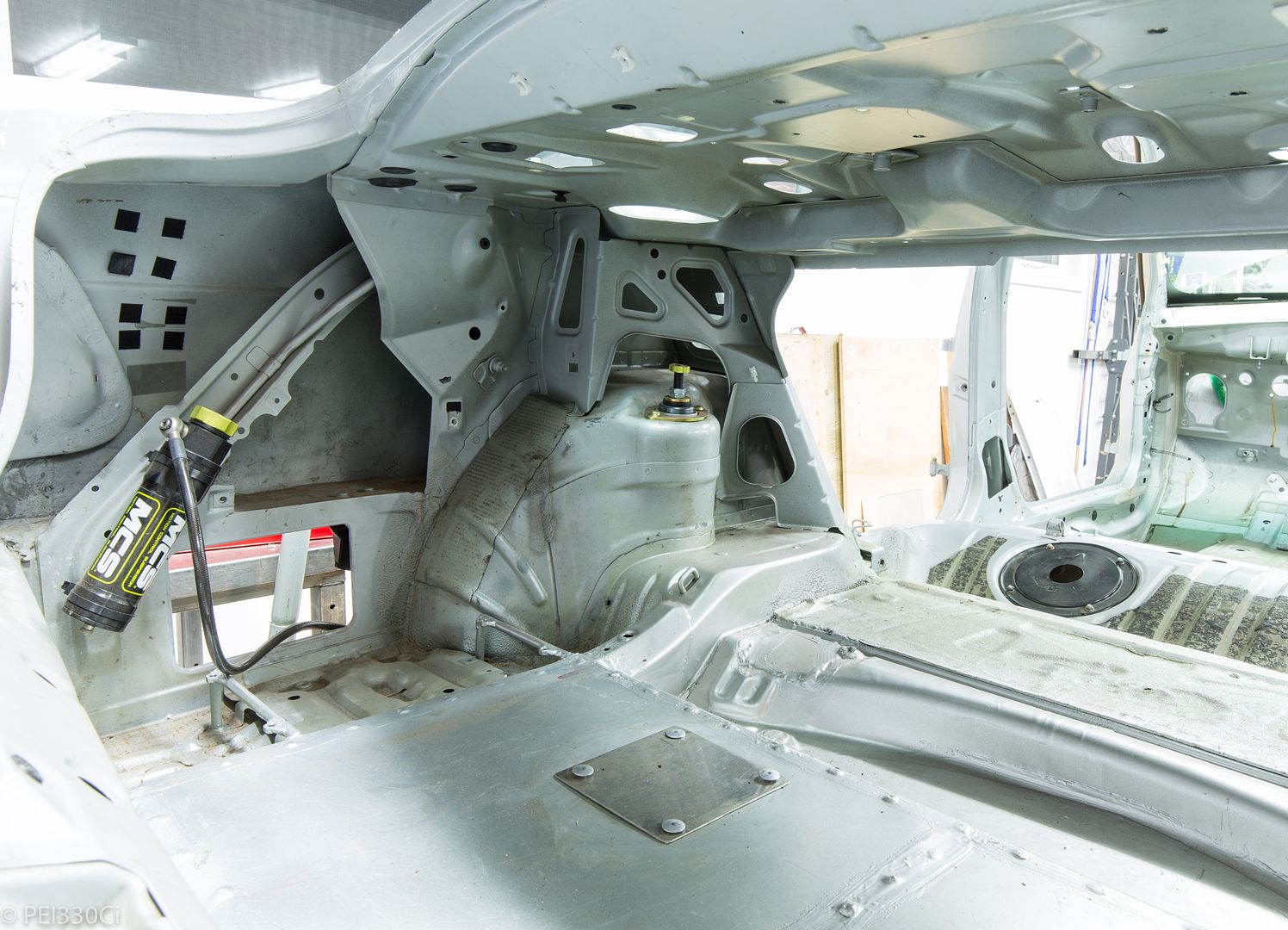
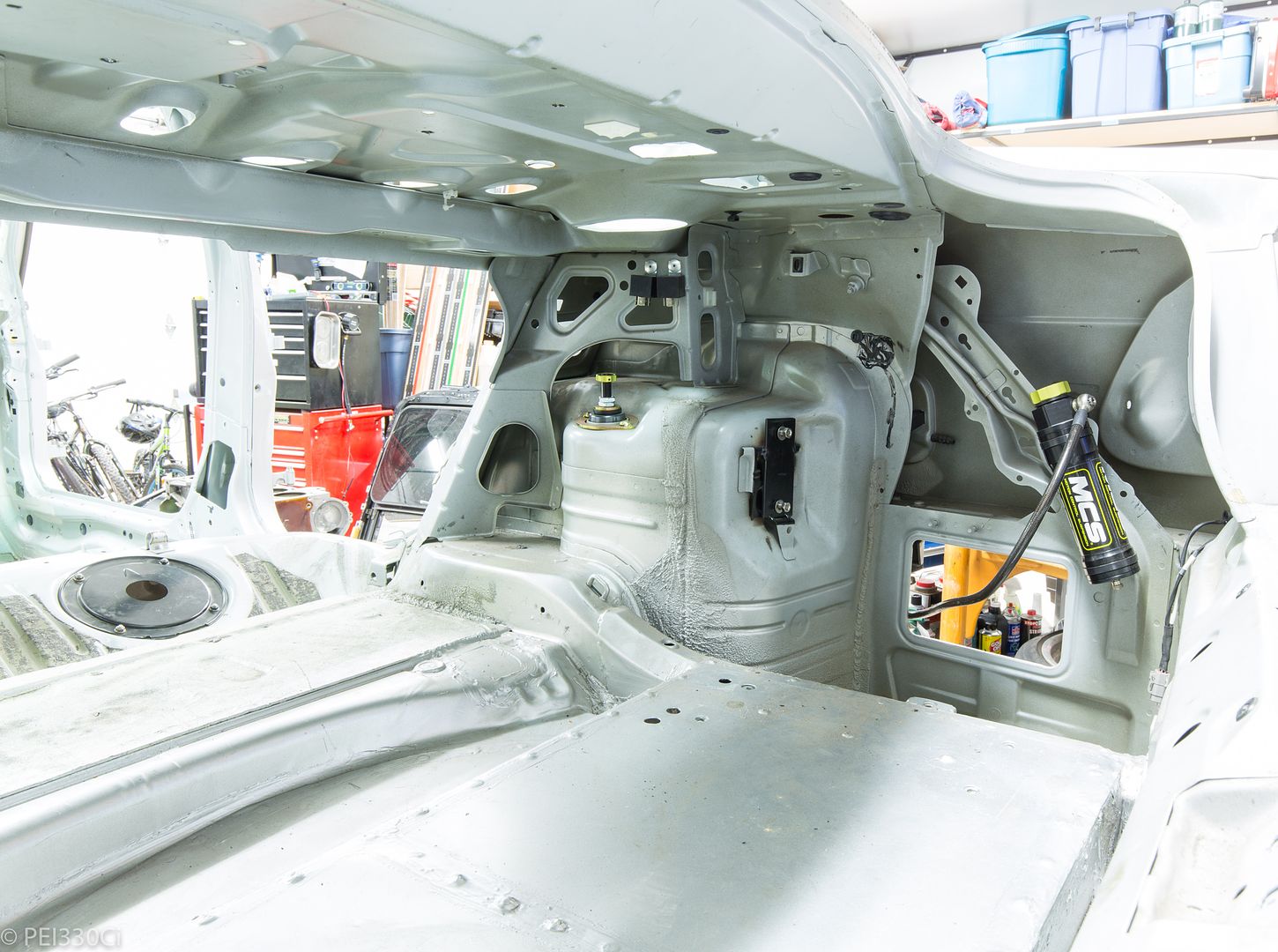
While I took great care in building the wiring harnesses for the engine back, I really struggled with all the electronics mounted in the "drug bin" area. A single bulk head connector would have wires going to 5 places making "simple" harness construction virtually impossible. Then, over the life of the car since 2014, many additional features and wires were added. The result was a mess that I was always keen to improve on in a future revision to the chassis. Now I have my chance:
All of the electronics will be mounted inside of the chassis in a single location, with a much cleaner wiring layout. (Think of my dash panel work as an example)
u owe my mule an apology
Here is that thread. If you know the installed height you can do the math backwards to get seat pressure and open pressure.
https://www.bimmerforums.com/forum/s...-vs-M52-vs-S52
As a pushrod v8 guy, don't try to use pushrod logic on a ohv engine. On a pushrod v8 you have to move a 2" + valve and spring and retainer, as well as a rocker arm, pushrod, and lifter, and they all have deflection in them which causes serious problems with hydraulic lifters and trying to get the same motion at the valve as you do at the lifter so you don't get seat bounce and not either collapse the lifter or pump it up. A lifter riding right on a valve that weighs half as much is a much simpler proposition to keep control of.
Last edited by someguy2800; 09-13-2018 at 12:42 PM.
86 325es, 2.8L m50, S476sxe, ProEFI 128 ecu, e85, solid rear axle, TH400 trans, 28x10.5w slicks, zip ties, popsicle sticks, tape
best time 9.06 @ 151.8 mph, best 60 foot 1.30
Member
Yes, you would save a lot of weight and complexity by getting rid of all that nonsense. I like recycling used tech, you have my mailing address.
Light Fires N Burn Tires
Shoot that is the one thing I have not checked with my bell housing. I am interested to see what they say.
M54B30 Inside
I ordered a set of Supertech springs, seats, and retainers. (84 Lb Seat Pressure)
Hey hey! Keep your mitts off my PDM....
M54B30 Inside
Cut it
M54B30 Inside
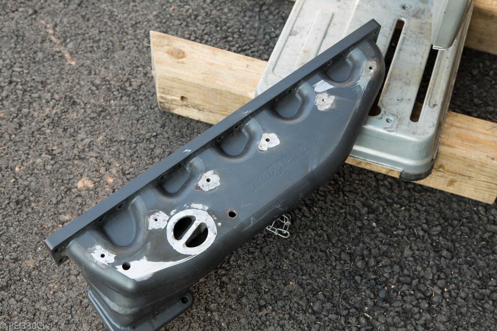
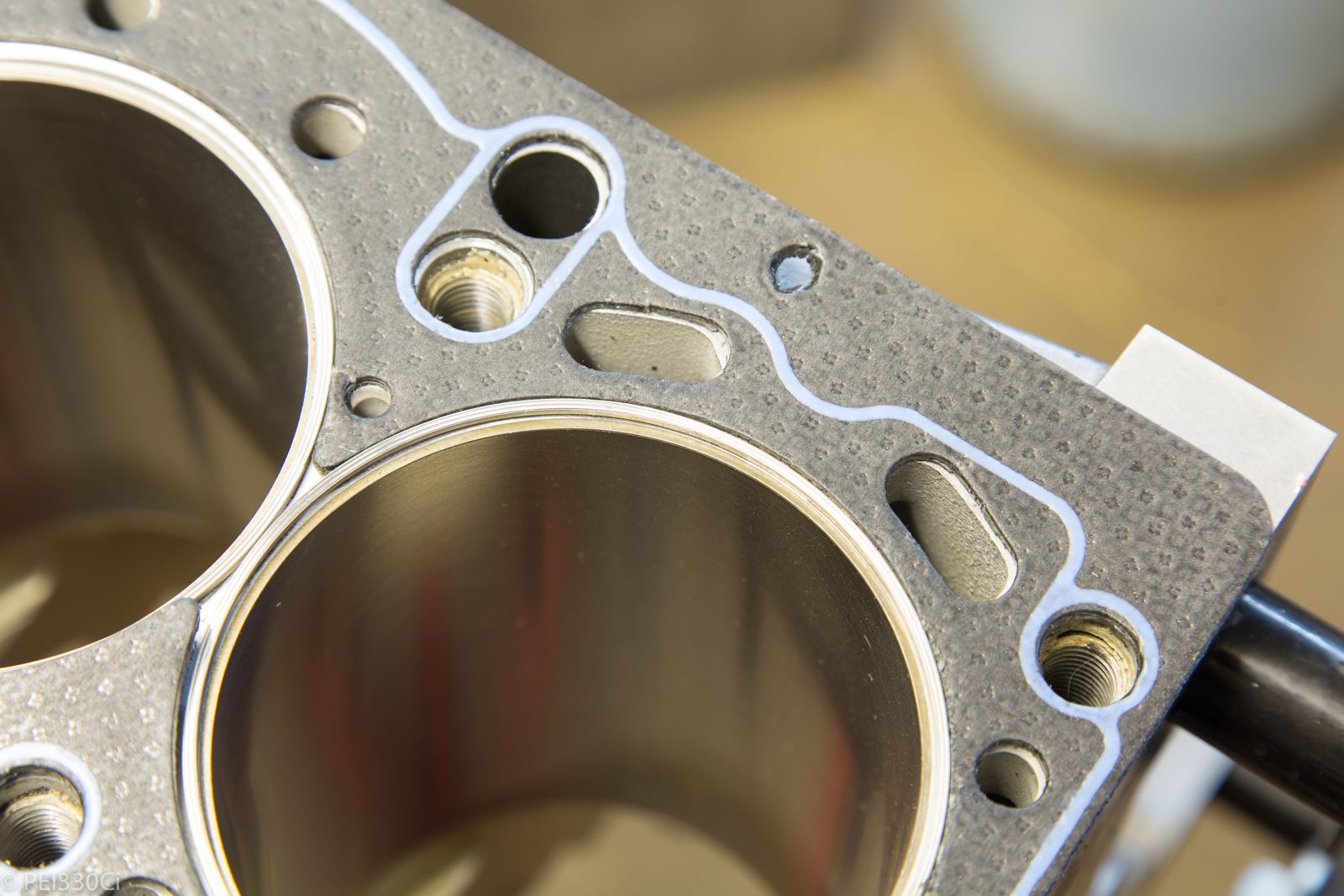
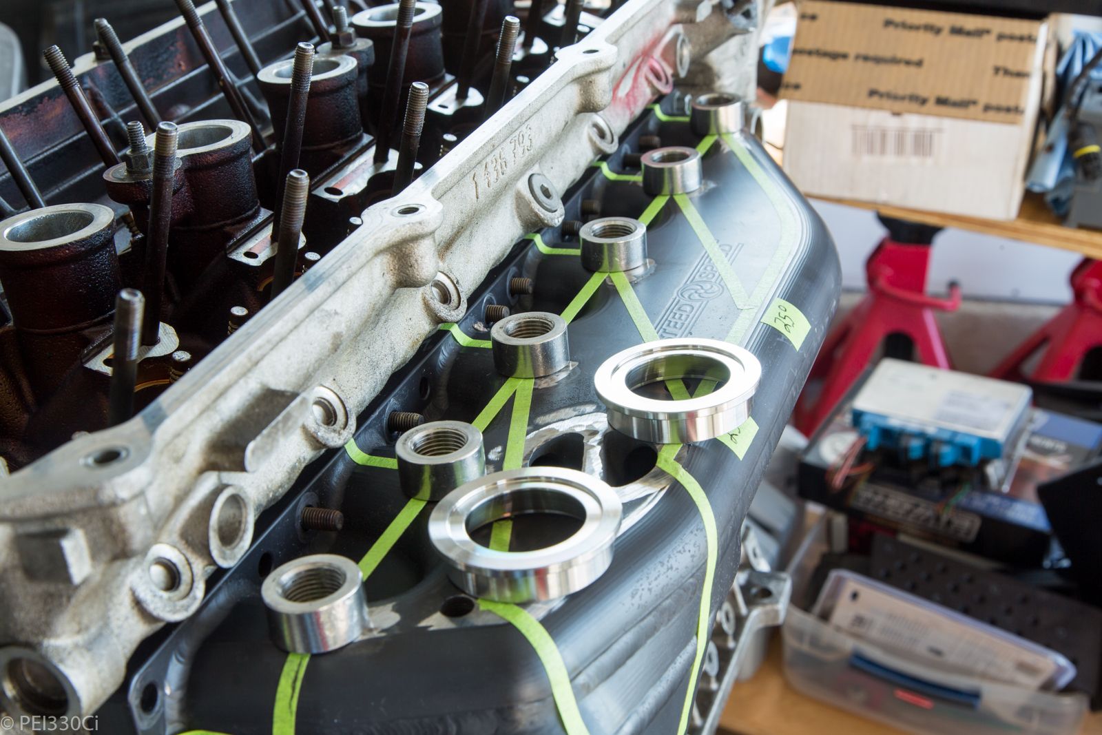
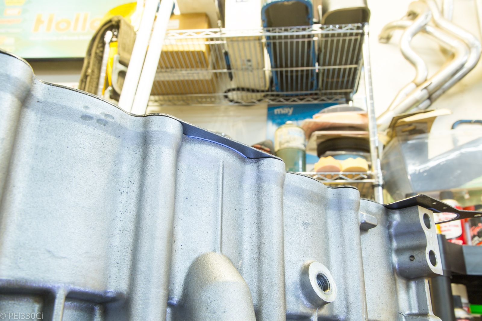
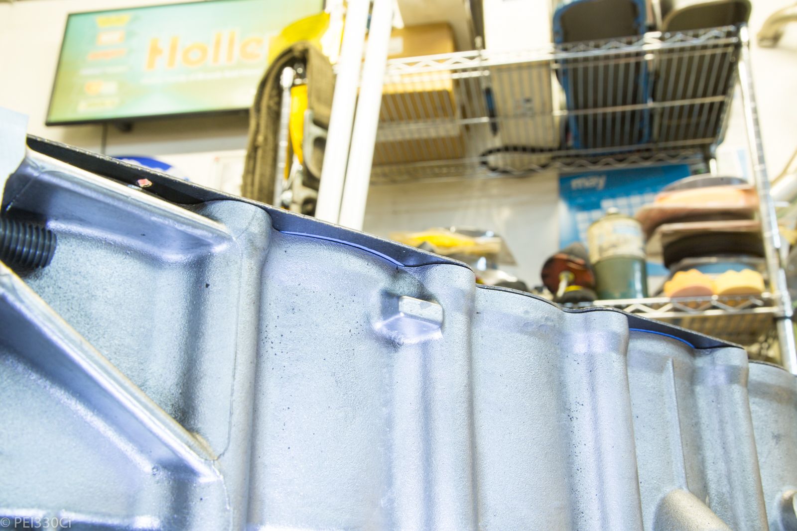
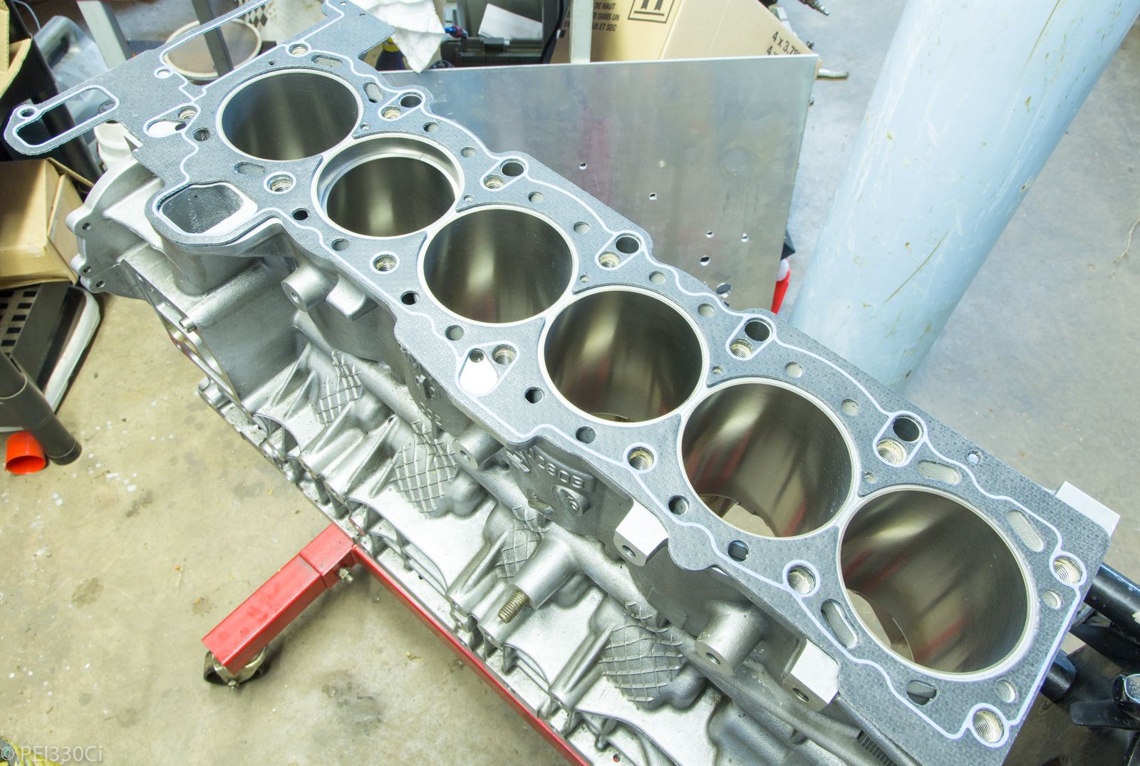
Everyone that has bought the Athena Cut-Ring gasket for the M54 has found that the sealing ridge on the exhaust side of cylinders 3 and 5 falls outside of the block:
Personally, I'm not too worried about it. I plan on putting a layer of sealant around that area to make up for it.
M54B30 Inside
The top:
Member
Can't see any pics.
M54B30 Inside
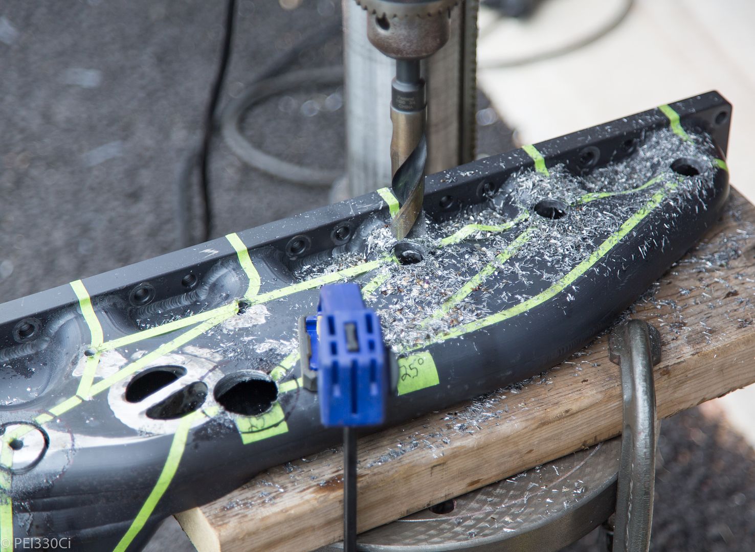
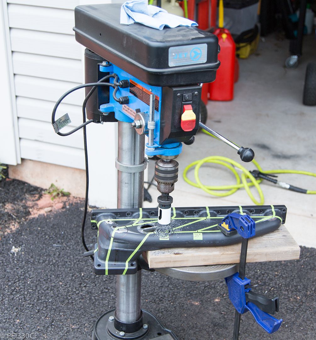
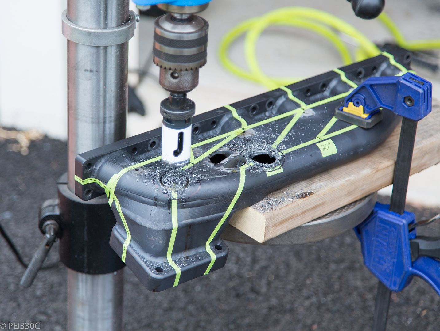
Drill it
Member
What is going on there?
M54B30 Inside
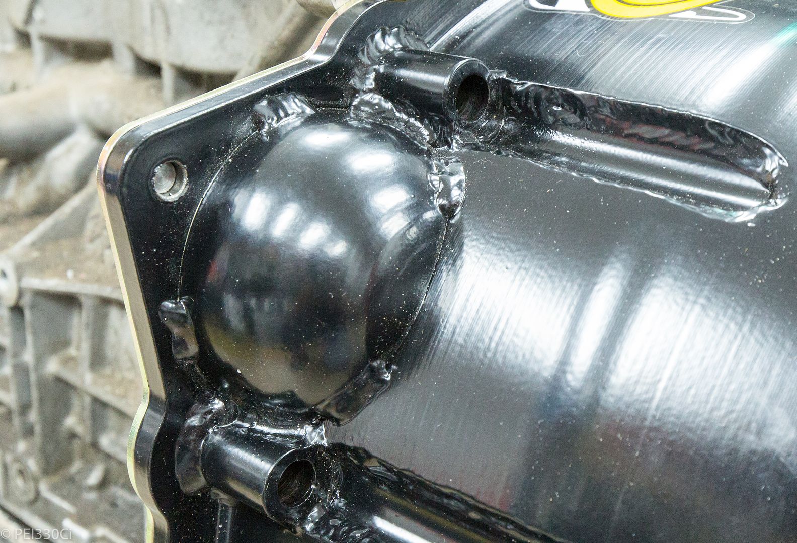
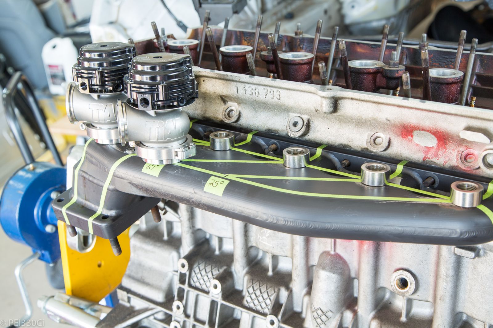
I'm going to run 8 waste gates.
M54B30 Inside
Or 6 Lambda sensors, and 2 MVS waste gates.
Sleeps with his eyes open
Where's the pressure tap for each so you can compensate for diffusion error as you deviate from stoich?
The wastegates look awesome and I'm super jealous your's has the Steedspeed logo in it! I never knew I wanted that until now..
Last edited by Kevin325i; 09-18-2018 at 07:47 PM.
Member
Neat!
M54B30 Inside
Are you referencing the affect of pressure on the Lambda value?
While I have the ability to write this into the code, and the means of measuring it, it hasn't proven to be as big of an issue as internet keyboard jockeys make out. I've had contact with someone who's gone through this on a boosted application, and they said their compensation values were smaller than what you might consider "trace noise" in the signal. Under real world conditions, the difference is smaller than our ability to compensate due to airflow dynamics.....
Sleeps with his eyes open
Unfortunately it is difficult to make a blanket statement because the error is dependent on deviation from stoich, pressure, and size of the oxygen diffusion membrane (basically the sensor you're using). Usually performance aftermarket lambda sensors downstream of the turbo without a catalyst have small error associated with pressure.
When you get into individual cylinder fuel flow and lambda readings especially right off the port I can with absolute certainty guarantee it makes a difference. Typically the assumption can be made that all the sensors have relatively the same pressure and a similar error so you can compensate the cylinder trims based on this. I have seen this work, and I have seen this cause calibrators to chase their tails.
Just do not trust the absolute reading or be surprised when you have the best results at .75 lambda or some other lower than you expect lambda value.
M54B30 Inside
I understand what you are saying, and I looked at adding the means to compensate for it, but in the end it is the relative values that are important to me. If all of the sensors are seeing a fairly similar pressure, they all should be affected in a similar way. Trimming individual cylinder fuelling, to make all of the sensors read the same value, could then be validated by a sensor after the collector. (or turbo) I do plan to run 7 sensors for this purpose.
The other thing to consider how proper pressure compensation works. It doesn't modify the measured lambda value, and make a correction. The proper way to do it is to use pressure to build a compensation into the lp (Pump current) value, which then gives a more accurate lambda reading. Most people don't have access to this in their Lambda controllers, so a more generic compensation can be done to the output value.
The good news is that pressure affects the values consistently. If the lambda value is under stoic (1.0), it will read richer with more pressure. If the value is above 1.0, it will read leaner with more pressure.
Another interesting thing that I've been looking at is the pump current. It's actually pretty cool to watch what it does under load....
M54B30 Inside
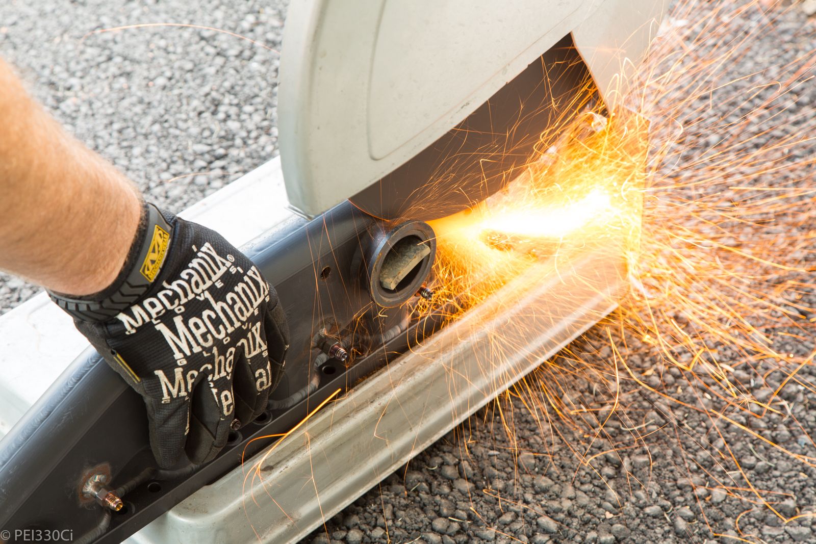
Transmission Tunnel - 0
Me -1
A cut-off wheel and a BFH wins the day.
 Posting Permissions


 Reply With Quote


Bookmarks