
 Member
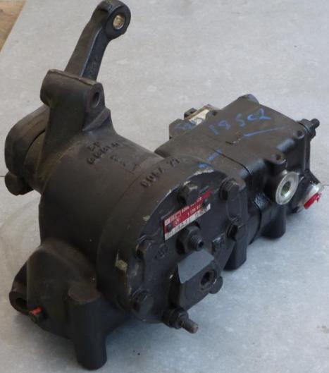
Here we remove the steering box from a 1997 bmw 840ci and replace about two dozen seals.
The motivation was to confirm a steering failure diagnosis that documented in another thread.
Earlier boxes and 850's will differ slightly.
This small task was made into a big challenge simply by the refusal by original manufacturer (ZF) to supply rebuild kits directly to end users.
The seals used herein are now precisely documented and in theory could be sourced independent of the oem.
The procedure shown below is not a complete rebuild because...
- My seal kit and documents did not cover the servotronic control.
- My tools, skill and kit did not cover the removal of roller bearings on the shafts.
- My documents did not reveal how to service the torsion control valve section of the input shaft.
**** Removal/Install ****
Time: about 30 minutes each way for the pro w/tools on game day. About 2-3 hrs each way for beginners.
Disconnect the battery and leave the steering wheel unlocked.
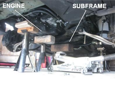
Jack the car, remove wheels and prop up the engine, independent of the subframe.
Position a lift under the subframe.
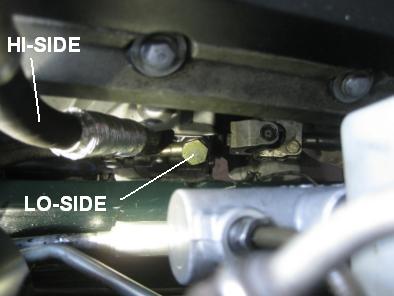
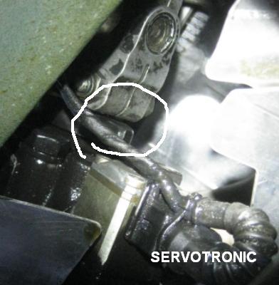
Disconnect hydraulic lines to the steering box, thus releasing fluid.
- Hi-side at regulator. 17mm.
- Lo-side at steering box. 22mm + 12inch extension.
- It's also a quick task to drain the reservoir (5mm hex) but I can't say whether that's absolutely essential.
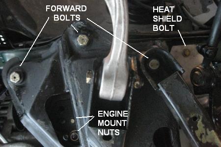
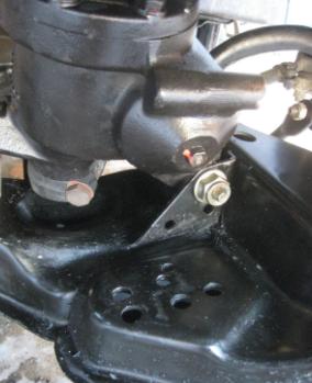
Unbolt the subframe.
Per side...
- 2 Engine mount nuts (17 & 13mm)
- 3 forward (17mm)
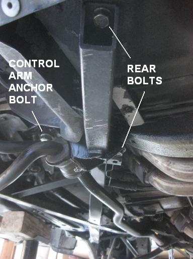
- 1 Control arm anchor (22mm)
- 2 rear (15mm)
- 1 heat shield (10mm)
Disconnect/unbolt...
- Servotronic harness
- Steering column U-joint.
Lower subframe.
!!! Tilt front of subframe down so that the steering box clears the V8 engine mount.
Only then will the box input separate from the steering column.
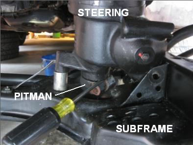
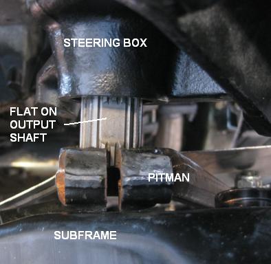
Disconnect the pitman arm from the steering box. 15mm + 6in extension
Unbolt and remove the steering box. 17mm & 17deep, 19mm & 19deep.
**** Disassembly ****
Time: 10min for the pro. 1hr for beginners.
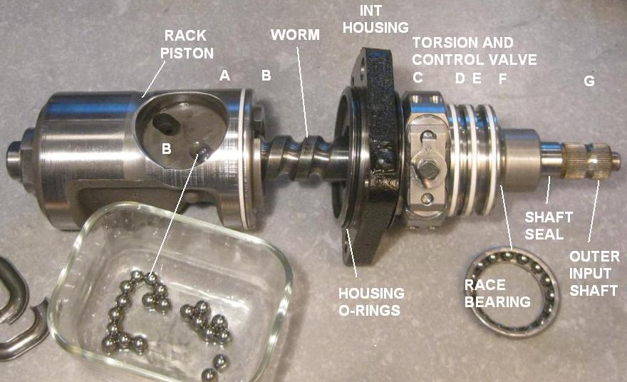
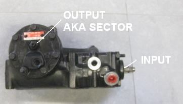
Vocabulary
Remove perimeter bolts on output shaft cover. Manage/track the washers buried by paint.
Remove locknut (17mm w/o paint) from lash adjuster on top of the cover.
Break paint seal (say with box cutter blades) and turn the lash adjuster (5mm hex) to pull the cover away from the housing.
Inside you will find...
- approx 1-1/2 cup (350ml) hydraulic fluid.
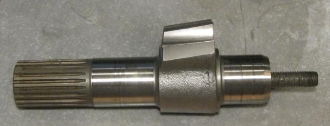
- the output shaft
- the rack
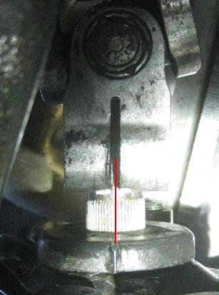
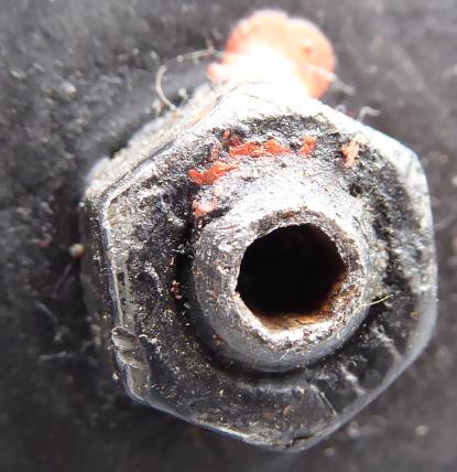
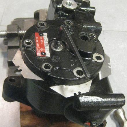
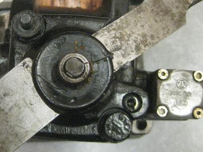
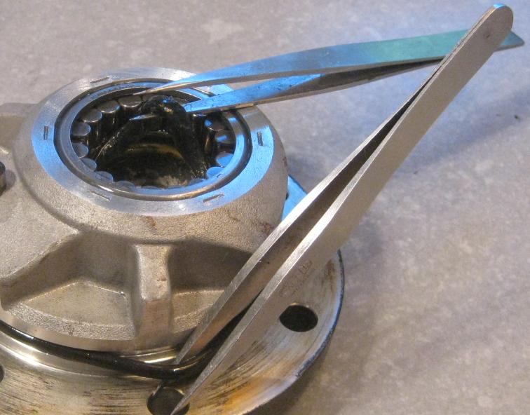
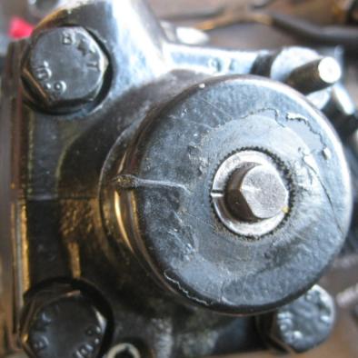
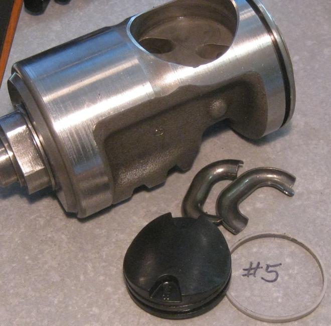
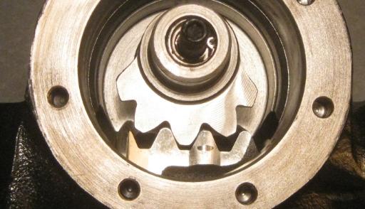
Remove the orientation cap on the input shaft.
Here opposing chisels unstick the cap from hardened gunk.
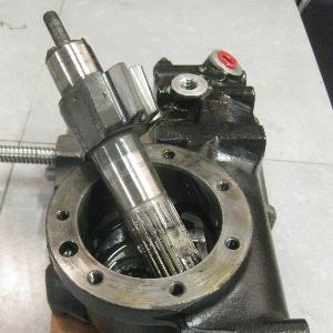
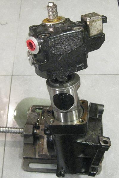
Unbolt the input shaft housing.
Break paint seal at either the input housing and the intermediate housing.
Remove the input shaft and rack.
The control section of the shaft contains about 1/2 cup (100ml) of hydraulic fluid.
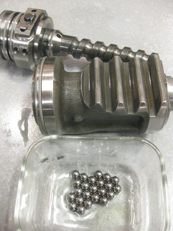
Separate the rack off the input shaft by rotating the input shaft (left-handed action, CW to remove).
Listen as the 23 balls fall and collect at the bottom of the rack.
**** Seal replacement ****
Time: 20 min for pro with organized inventory. 2hrs for the confused beginner.
A seal kit was obtained, definitely without any thanks to the oem.
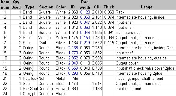
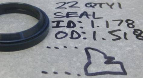
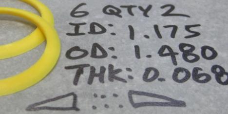
The part numbers shown in pics below were assigned arbitrarily as I inventoried the kit and wrote out a spreadsheet.
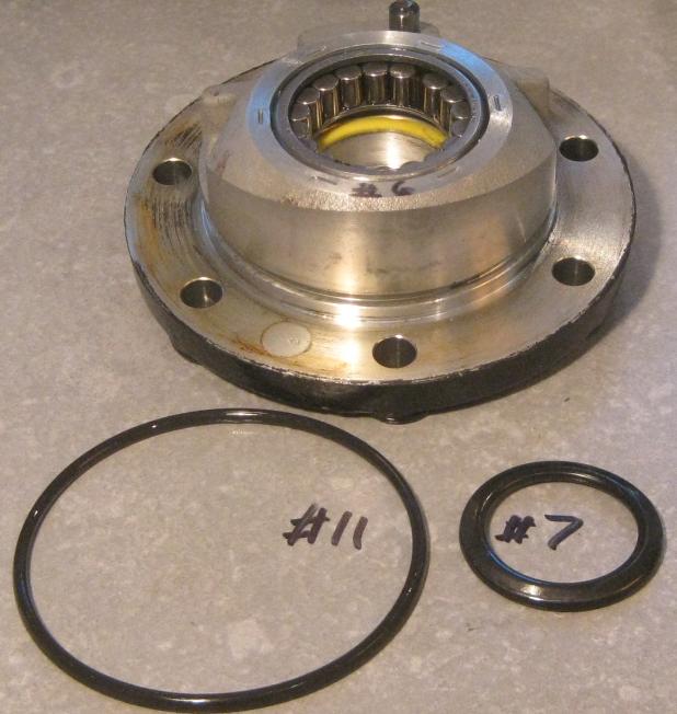
The output cover, using magic tweezers.
- Oval seal, inside #7
- O-ring, outside #11
The roller bearing on the cover prevented replacement (by me) of...
- Yellow seal, #6
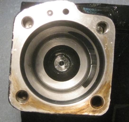
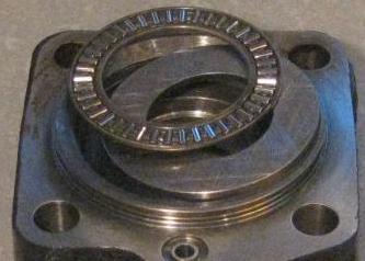
Housing seals at outshaft lower end.
- Oval seal, inside, #7.
The roller bearing on the housing prevent replacement (by me) of...
- yellow seal, #6
- blue seal, #22
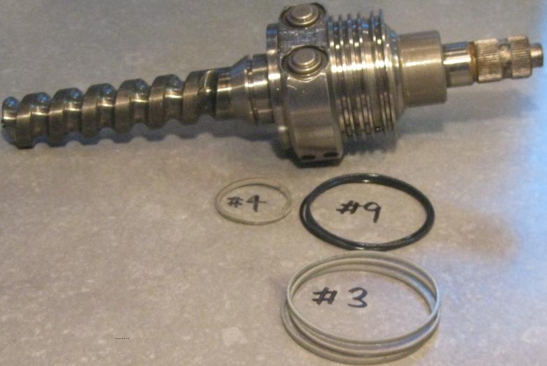
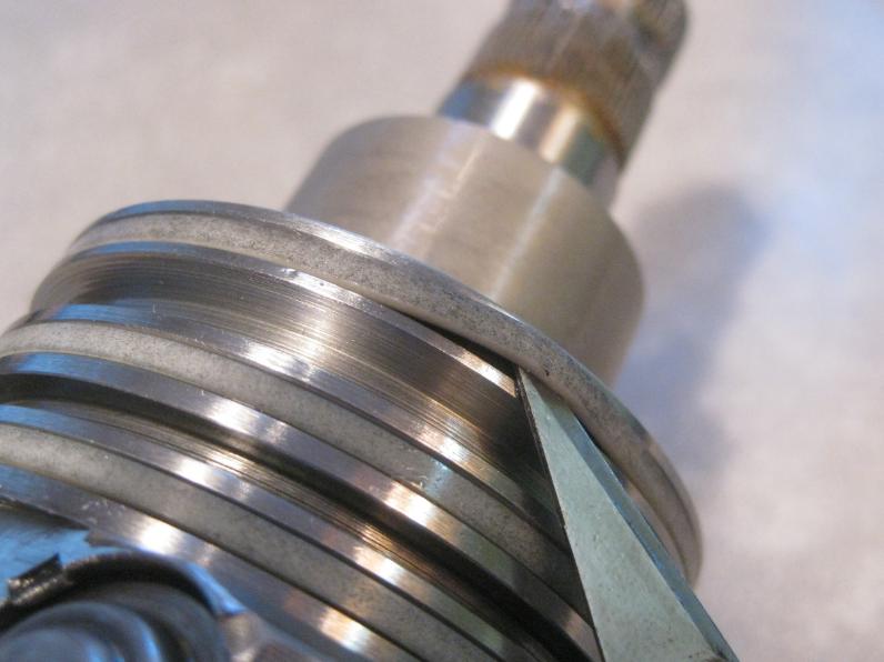
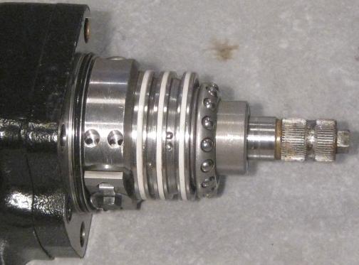
Input shaft.
- Bands, #3
- O-rings, #9
- Band, #4
Original bands, layered over o-rings.
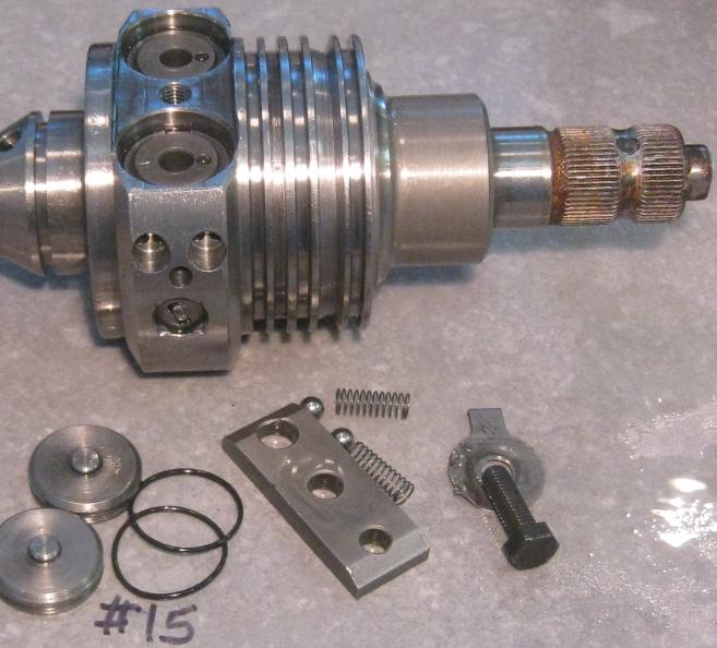
Check valve cover
- O-ring, #15
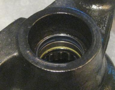
Input housing.
This spring seal was not replaced due to tooling and priority.
- Spring seal, #23 (not 22 as per typo in manifest).
Input shaft cap, #24.
The pointer is an extension of the tick on the shaft, covered by the U-joint during install. Shown not seated yet.
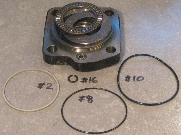
Intermediate housing, control side
- Band, #2
- O-ring, #8
- O-ring, #10
- O-ring, #16
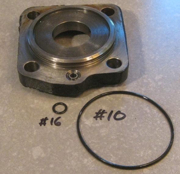
Intermediate housing, rack side
- O-ring, #10
- O-ring, #16
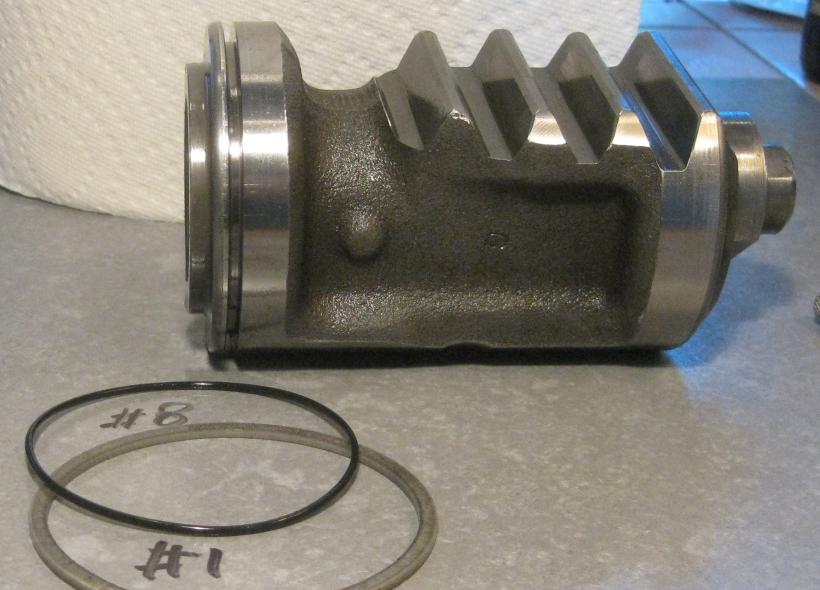
Rack
- Band, #1
- O-ring #8
Rack recirc cover
- Band, #5
**** Assembly notes *****
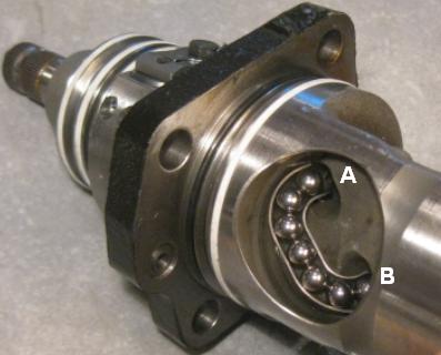
Position the input shaft in the rack with approximate 6cm separation.
Insert qty 16 balls into hole A and rotate the input shaft until they appear at hole B.
Be alert for jamming, else start over.
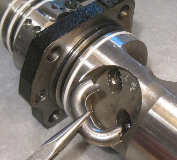
Fill the recirc pipe with the remaining 7 balls and insert from A to B.
Fyi: The top shell has been withheld just for this pic, but this sequencing actually won't work. The balls interfer with the insertion of the half-shell.
The successful technique is to assemble and load the the recirc pipe,
then keep the rack and pipe almost level so that no balls fall out on either side,
then bring the pipe and rack together.
The hi-side hydraulic line must be installed blind. There is no access after box installation.
It has been demonstated that coming staight out to the side provides the correct orientation to mate with the regulator.
Shopcraft while we are here: This note was written six weeks prior, telling myself about the state of the project.
**** Install notes ****
Both the pitman arm and steering column U-joint have an rotation alignment according to tick marks on the shaft ends.
The convenient proxy on the pitman arm is the flat on the shaft where the pinch bolt passes.
Then raise the subframe, trailing end first until the box clears the V8 mount.
The column U-joint aligns with the pointer on the input shaft cap.
Member
That's my aggravation.Originally Posted by CaifanSC

I could not and can not find any to measurement or observation that says this box (or seal) is good or bad.
Just now I got back from my first test drive following the swap out of a used working temp (#2). The rebuilt original (#1) now works perfectly.
Before, it consistently failed to provide assist and seemed to bypass so much fluid that the brake assist also went away. I have a theory, but that's typical.
Still waiting on a 2K psi sensor, to be continued on the original thread.
Member
Seals fall into only 3 function categories.
- Piston
- Control chambers
- Housing & shaft ends
[professor-style]
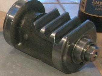
Recirculating ball steering povides assist by pushing the rack (a piston with teeth on the far side)
along the worm gear, attempting to minimize torsion between the worm portion of the shaft and the outer input shaft.
A thinner/weaker torsion bar puts less burden on the driver before the control valves apply assisting force on the piston.
In the pic below the letters A->F indicate 6 pressure zones created by the seals with zone G being outside/atmospheric.
Applying pressure to the piston in zone B above that of zone A will assist a right turn, and applying pressure to A above B assists to the left.
A band-over-ring on the piston separates zone A and B and notibly the band around the recirc cover does also.
If this seal were to fail then not only would there be no assist but presumably fluid would flow directly from source (zone C) to drain (zone F).
The chambers C->E allow control pressures to be passed from the rotating shaft to-and-from the stationary housing.
For instance the Servotronic servo could create an intentional leak between control chambers.
Finally, ordinary o-rings and shaft seals sorta keep hydraulic fluid from leaking to the outside world.
[/professor-style]
MAX@FINEMOTORING.COM
Hat's off to a great write-up, thanks. Were either of those kits by themselves completely able to do the job? If so, which one?
If I'd been a little more alert, I could have sent you an inside puller to get those bearings out. A cheapie Harbor Freight job ought to work OK.
You can also check the recirculator ball diameter and, to a lesser extent, the wear on the ball track. The balls start out at 7mm. If both the balls and the track are a bit worn, you can try replacing them with 9/32" balls, which is nominally 7.14m. There's old forum chat about this being a way to tighten up some of the slack.
How come the middle half of any project always takes the most time?
Member
Yes Mr Lumens, thanks for contributing all the little goodies that made this project happen.
I ended up using or at least identifying a home for 27 bits, thus leaving me with 5 and 9 mystery parts in the two kits.
The mystery parts were sufficiently large that they could only go into the torsion valve section which I (literally) failed to open up.
The other mismatch occurred when I dived into the servotronic switch and found lack of support in the kit. Not surprising as not all boxes have it.
I hope you push further on kit development for the great masses of people who will now follow.
To that end, I now have box #2 on the bench and I'm willing to tear it down to confirm this or that.
I would need docs or at least a good tip on the torsion valve section and also seals for the servo.
*****
Box #1 was never leaking to the outside, so I wasn't concerned with replacing housing and shaft seals.
But as for the shaft seal, my mind was actually fixing on the roller bearing being staked into place.
Also, if I pull the roller bearing to replace shaft seals, where is my replacement roller bearing?
So I took a pass on shaft seals because it didn't meet a basic risk/reward calculus.
Member
Could this repair a worn box. I have a huge slack in mine. Huge one
MAX@FINEMOTORING.COM
Weren't the blue and yellow seals at the bearings 100% polyurethane, ie no steel form underneath the poly and no spring gaiter? I'm just wondering if there's any way to pull them without removing the bearings.
How come the middle half of any project always takes the most time?
Member
I don't see that happening. This contrasts with the silver oval-sections which were very pliant and, for removal, the outbound set could be stabbed into by the magic tweezers.
[professor-style]
***** Lash adjust *****
aka "tightness"
The teeth on the output (sector) shaft are beveled in the axial direction.
Pushing against the top cover, the adjuster bolt forces the output shaft down onto an opposing bevel on the rack/piston.
That by itself would adjust lash at this junction.
This would force the piston to rotate in the bore if not constrained by the housing.
The piston may (!) be forced towards the input shaft, taking up slack against the recirculating balls.
System level drag increases as we clamp down, requiring the hydraulics to work harder.
[/professor-style]
MAX@FINEMOTORING.COM
You might be surprised. You can double fold a poly seal and work it into some improbable bores. I had poly u-cup seals made for the input shaft on the brake boosters, and you could stuff them into a 22mm bore. I don't have any more of the steering box seals at the moment so I can't compare.
How come the middle half of any project always takes the most time?
Member
Now that my front end is rebuilt, I can feel bit of play in my steering wheel. I think you (Hyper) even made a sly comment about it when I saw the freshly rebuilt gear on your bench and I noted I was glad I didn't have to dive into mine because mine was fine!
You said:
"The teeth on the output (sector) shaft are beveled in the axial direction. Pushing against the top cover, the adjuster bolt forces the output shaft down onto an opposing bevel on the rack/piston.
That by itself would adjust lash at this junction."
So, if I am understanding you, if you screw the allen bolt "down into" the box you can remove some of the play, downside being increased friction?
This all depends, I suppose, as to whether a standard or reverse thread is used on the allen bolt, which clarifies screws "down into" as being a clockwise or counterclockwise turn as viewed from above.
Is there any official spec for the gear lash adjustment?
1995 BMW 840Ci
1999 Porsche 996 Cabriolet, 6 speed
1974 VW Westfalia P27 Deluxe camper
1974 Mercedes 280C
Member
This writeup does not attempt to cover testing or adjusting.
You would have to hit up someone like Mr Lumen, who has spent much more time with these boxes and suppliers.
However, I recall him saying that special tools would be needed to verify factory specs.
I merely put my box back together the way I found it.
Between the road and steering wheel there might be a dozen sources of "play", and I can quickly think of three inside the box.
For instance while the assist was out, I got quite familiar over a 1500 mile stretch, with the 2 degrees of steering wheel slop before the torsion bar hit the stops and I could move the rack.
The adjustment bolt takes care of the rack-outshaft junction for sure, but may (?) also tighten up on the recirc balls. I just won't guarantee it.
Yes, the adjusting bolt has standard right hand threads.
By design, the outshaft can move up and down, over a range of say 15mm, and turning the bolt CW as viewed from above would push the outshaft down onto the rack teeth.
Member
Hyper. If my box is worn and has a slack can I fix that?
Also, I have a RHD CSI box and it is supposed to have different ratio. Could I swap the internals?
Member
No and no.
You're a student and don't have time.
Member
So the RHD is useless for me?
Time is all I dont have during the winters, but maybe I could find some during the summer
Member
Does anybody know if E32 box fits E31? I know that ratio is probably different, but are they physicaly the same?
MAX@FINEMOTORING.COM
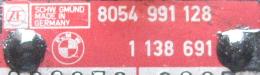
Yes, they are. There is lots of interchangeability among the models. Earlier e24s and e28s had big nuts that held the pitman arm on, but the internals were the same as later boxes. There are dozens of ZF part numbers, but they mostly specify very minor differences like port connections or torsion bar specs.
- - - Updated - - -
Have a look in the sections for OTHER cars in the BMW online manual; there were lots of chapters left out of the e31 manual.
BMWTIS -- Repair Information
- - - Updated - - -
Totally. The spiral on the worm gear is the opposite direction, since the sector shaft is on the opposite side of the box.
How come the middle half of any project always takes the most time?
Member
Where did You obtain those White square gaskets and O-rings beneath them.
My box is from B12 Coupe without servotronic bun I think the inner parts are the same ?
shade tree mechanic
Moderator
Is that seal kit available somewhere as a kit or is that bought all separately, and where? I am especially interested in the white square gaskets for the chambers C->E which allow control pressures to be passed from the rotating shaft to-and-from the stationary housing.
Last edited by shogun; 06-25-2019 at 10:55 AM.
Shogun tricks and tips for the E32 series are HERE!
Member
In a fantasy world, someone would have picked up the (american style) football and ran with it, doing an around-end of the opposing team, the OEM protecting their rebuilder channel.
In reality someone has to own the unenviable project of visiting seal manufacturers and convincing them to produce all or part of a kit. And in reality, no one is being sponsored to accomplish such a job.
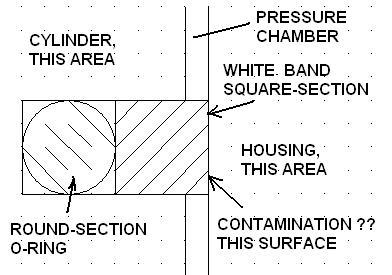
My instinct is that it is not incorrect to focus on the pressure zones C->E as these would have inordinate influence over operations.
It had caught my attention (with no further proof) that in my case, 1) the white square-section bands may have been contaminated/embedded with metallic debris, perhaps delivered from elsewhere by the circulation in the hydraulic fluid, and that 2) this may lead to a failure to isolate the control chambers.
Note also that within each of the 3 radial slots, that the white band covers a standard round-section O-ring, which I assume to be the ultimate source of force pressing the white bands against the inside wall of the housing. Hence, any degradation in the O-ring properties might also show up as a failure to seal chambers C->E. Hence, the restoring of such properties might lead to properly sealed chambers.
In a fantasy world, on the bench top, you would apply remedial action and then immediately verify the result (via leak down), but in the real world you might have re-install the unit and just hope that anything has changed for the better.
MORΩN ΛABIA
BMW CCA Member
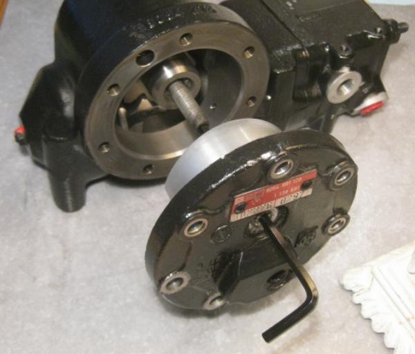
You mention removing the wormshaft, which is back-loaded on these. My question concerns the front of the wormshaft and where it meets the housing: what goes on there? Is the paint-marked bolt on the very front of the steerbox housing a wormshaft lash adjuster? I did this once on an ancient Mazda steerbox, after we had replaced every last steering component, tightened the normal (sector) lash, started to tear our hair out, removed the box intending to replace it... and found a giant nut around the worm (input) shaft. Tightening that was the cure. Did this on my Yota, too, which required a special tool but minimal disassembly. I'm chasing a steering slop problem on an E34 with a similar situation (and the same box as your E31), looking for info.
Member
The mission in this thread is/was seal replacement, hence its titled "overhaul" rather than "rebuild" where we would check clearance and wear, follow procedures and testing to achieve factory spec.
We, the public, lack such tools and documentation.
So, although I can't say what that nut is, what it does, or how to use it, I can say it did not involved seals and therefore it got only a casual glance during the project.
I sort of recall staring down the input/worm barrel and not coming to any obvious conclusions.
Just now I pulled the box out of storage to check if had the allen/hex wrench thing going on.
Yep, but I exhausted my entire bin of allen wrenches, both metric and imperial, and yet didn't find a satisfying fit.
It's half-way between a smallish 2.5mm and 3.
Anyway, paint plus allen probably equals adjustment feature.
Use at your own peril or delight.
MORΩN ΛABIA
BMW CCA Member
Excellent; I couldn't see the allen hole before, but that's a lash adjuster if I ever saw one. Peril and delight await!
Member
Since you fancy wild guesses, here is mine...
It's an adjustment to the end stop of the rack travel.
And rather than just a mechanical stop, it forces open a ball valve (that I think I'm detecting) in the end of the piston, cutting to zero the pressure difference across the piston seal.
Why an adjustment? Well, that would take another guess, and I'm a busy man.
MORΩN ΛABIA
BMW CCA Member
3mm was a perfect fit on mine. Your guess seems right; tightening or loosening didn't seem to do much, but any effect may have been masked by the rather heavy steering (car in the air and off), possibly because the balljoints and tierods are nearly brand-new and still stiff. I played with it a bit, reset to paint mark, found and fixed the problem elsewhere. Thanks!
So there is no wormshaft lash adjustment?
Member
Doesn't seem likely.
I did not observe that the worm was anything but continuous from end-to-end, although I suppose it could be a two-piece {edit: duh, has to be 2-piece, otherwise we can't sense and react to torque}.
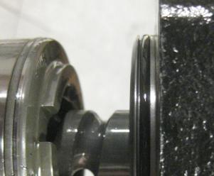
Once the control section is affixed (someway/somehow) to the shaft, the control section and thus the entire worm assembly is constrained by a torrington...
...and a ball-in-race...
...keeping the control section chambers centered on holes in the housing.
We would not want the chambers moving with respect to these housing inlet/outlets.
So your only hope is if the control section can be re-positioned along the shaft (someway/somehow).
This hypothetical procedure would require complete disassembly of the entire box down to bottom level components and therefore couldn't be called "an adjustment".
*****
I'm an analytical thinker and use the word "guess" if I am merely 99% certain.
The hazard in disabling with the assumed piston stop is that, if hydraulic pressure is not killed at the end of travel, then the piston attempts to force the case apart with (hydraulic pressure x bore area ='s) perhaps 3 tons of pressure.
Going the other way I'll guess there is some comparable fail safe, possibly the end of the worm shaft popping yet another check valve inside the piston.
****
Others have mentioned that if one runs out of sector/output shaft adjustment, then one might consider swapping imperial balls for the original millimeter.
Can't comment on that problem or solution, especially in this thread about seal replacement.
 Posting Permissions


Bookmarks