
 Member
I'm fixing a few things the shop didn't get quite right on my frankenmotor. I'm putting OBD I electronics on an M62, which requires a number of simple modifications. At least they should be simple. I didn't want to mess with the timing, so I outsourced it. Now I'm redoing it. I can't find a specification for the air gap between the cam sensor and the pin. Anyone know or have an M60 apart that can check?
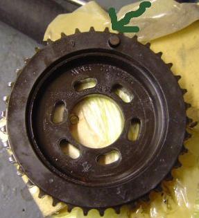
Also, the shop did not leave a straight edge on the tooth I'm using to trigger the cam sensor. I think this cam sensor is a simple variable reluctor type. How tolerant is the ecu to irregularities in the waveform the sensor puts out? What is the harm in letting the cam sensor trigger a couple of degrees early? I'm attaching a picture of the modified reluctor ring and the tooth that will trigger the sensor. The tooth is at about the 6:00 position, and you can see area that is supposed to trigger the sensor is offset by about 2mm from the leading edge (left side as you look at it). I've since removed all the excess metal from the surrounding teeth such that only the trigger tooth sits proud of the ring. Any help would be appreciated.
Brett
Member
The same M60->M62 project was accomplished in a 5-series back in 2008. Probably elsewhere too.
Although the pics are not presently showing on that thread, some have been captured by me.
That thread does document the sensing method(s) but not the exact answer to your question, re: air gap.
The captured pics don't help down to that detail. Best to take your own M60 apart, if it is still around.
****
Since there are other variables besides air gap, I would further recommend O-scoping your finished result.
I don't know an exact requirement on the DME input but I would look for a peak-to-peak sensor output well above 10V at idle speeds.
{ed: No. Need it to function at an even lower speed, at cranking, where hall sensing gains advantage.}
Re: waveform. Probably edge triggered, so just don't reverse the slope, especially around the zero crossing.
Re: exact timing. Typically this is provided by the crank, and the cam sensor (on a fixed-phase cam) only indicates the side of the crank cycle.
****
These projects indicate a need for a spoofing box, M62 impulse wheel + hall sensor -> VR DME input, formerly from the pin-on-sprocket.
This would eliminate the mechanical hack.
Hypothetical box could also help out with the issue of rear v front crank pickup, providing that a sensor hole and pickup is already present (a tranny issue iirc).
****
My ETV box from the UpBeforeSix project can be reprogrammed to do the job, but...
1) It is overkill, too elaborate.
2) I don't have time to get involved, to build something simple as req'd. I'll put it on the list.
Last edited by Hyper; 12-24-2018 at 09:52 PM. Reason: Idle v cranking
Member
Thanks, Hyper. I didn't know you were involved with that build. That was one of the threads that made me decide to go ahead and build one myself. Actually, I'm wishing I had done it all myself, because going back and fixing mistakes is hard, especially when the shop cannibalized my M60 already, so it cannot be used for reference any more. I've found a crank sensor air gap spec of .5 to 1.5 mm, but I think that is for a hall effect vs. reluctance sensor. I'll set the cam air gap to that spec and see what happens. I've heard the cam sensor is only used to determine the side of the cam on this motor, so my thought is that it isn't a big deal if it triggers a couple of degrees early...or am I missing something?
Member
No, not missing something, but these corrections to your post:
* I have nothing to do with the 2008 M60->M62 project and so can not help you out with the details on sensors and signals. Instead my project was 2014 M62->M62TU vanos, using the M62TU46 as an example. I have no HANDS-ON experience with the M60 or its sensing, only general experience with engine controls as applied to other engines.
* The crank sensing on both the M60 and M62 engines is VR. The M62 cam sensing is definitely hall tech, and I am assuming the M60 cam is VR tech because it looks like VR tech.
* On the M60, the crank and cam pickups are not necessarily related in signal quality.
******
Just so that everyone else can follow the discussion...
The M62 (simplex) cam sprocket is originally adorned with the (fixed-phase) impulse wheel.
I labeled it a CYLID (ie cylinder ID) wheel because IMO its only purpose is to establish where we are in the firing order.
On the other hand I label the M62TU impulse wheel a CAS (ie cam angle sensor) because we really do care about the (variable) degrees of cam phase.
In the 2008 M60->M62 by others, the above impulse wheel is butchered to produce a comparable exciter to the M60 pin on the (duplex) sprocket.
Pic credit, OP for the 2008 project.
*******
In a hypothetical M60->M62 project done electronically rather than by mechanical hack, we would start with the M62 impulse wheel signal and devolve it back to the M60 pin pulse for input into the circa OBD1 DME.
To do it electronically as proposed would require that I find 6 weeks in my schedule to do some simpler app-specific hardware, clean up the code base, test it, etc.
Fyi, in my M62->M62TU project, we start with a variable-phase signal coming off the M62TU CAS wheel and convert it to the fixed phase M62 CYLID target signal.
*****
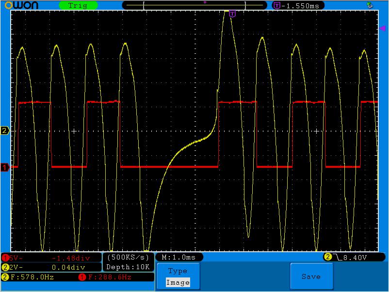
Just for fun but almost unrelated, here is the (VR) crank signal coming off the M62 (yellow trace) and my ETV box capturing the positive slopes just after the zero crossing (red trace).
The reason for me including this here, is so you can see an example of VR signal strength (about 17V) and shape.
The extra gap in the center is the key on the 60-2 wheel flying by.
Because the crank wheel has 60 teeth, we can directly correlate frequency to rpm. ie, we are at idle, 578 rpm.
The reason why we capture only positive slopes rather than both positive and negative, is that then the measured periods are constant, independent of level shift with respect to trigger level.
When a long period DOES show up that does not match the typical period, then we know its the key and this confirms where the crank is.
Then the only info missing is what side of the cam cycle we are on, and this is supplied by the cam signal.
For the M60, a simple pulse. For the M62 and M62TU, a slightly more robust & enlightening PWM encoding.
If there is no M62 style pickup in your project, then we assume the M60 style sensor kicks out something similar, perhaps with a different rotational offset, but maybe the same.
Member
The question is, how to convert the cam sensor output without the mechanical hack.
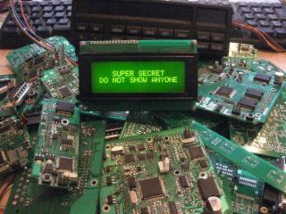
So I got to looking thru my vast library of Super Secret Boxes...
...and found something that was both current and close enough to do some immediate investigation, without the overhead of producing new hardware.
***** Sidebar *******
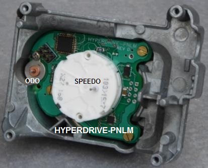
First, an introduction to this particular SSB that I code name PNLM, which stands for instrument PaNeL with Motors.
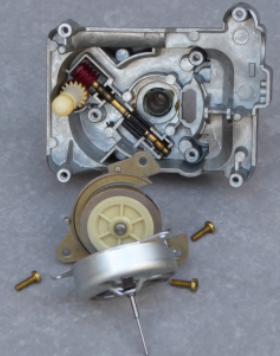
Its from the Mercedes kingdom and the reason for its existence is that I was updating my 190E-16V away from its original trannys (717.404 & 722.408) which have a MECHANICAL speedo drive output, to a newer 5-spd tranny (722.605) with no such output.
Here is the mechanical guts of the original speedo + odometer head.
and here is my electronic retrofit using stepper motors for the speedo needle and odometer gear train.
***** Back to M60 -> M62 stuff *********
The reason why this is relevant to the M60->M62 swap is that, as-is, the PNLM checks off the following boxes.
- Simple, compact, low cost.
- Has a USB port allowing communication to host (desktop) software.
- Has the most recent version of the my VR sensing circuit, to be re-purposed as a crank sensor input.
- Has a VR "high" voltage output, to be re-purposed as a cam sensor output.
A VR output is featured on the PNLM because on early W201's the VSS comes from a VR sensor on the speedo head, monitoring the mechanical cable drive.
With the W201's VSS sensor going away, the VSS must instead be generated in software.
Similar deal cam sensing, M60 v M62.
So for immediate proof of concept, we leave off the motors and their drivers and hack in one additional input to read the PWM coming off the M62 impulse wheel.
Then we go looking thru the Hyperdrive-ETV software routines for crank & cam related code to download into the -PNLM.
Member
You're right--that sounds like an immense amount of work! I asked my shop to follow the procedure in the thread below, except they didn't read it all the way to where you rotate the reluctor ring to select a whole tooth. Instead, they marked and cut a dog leg. The good news for those following is that the procedure in the thread below locates the exact tooth I'm using, and my shop counted teeth on each wheel to verify. If it works for me, that will validate the procedure the thread below used. If I can get the air gap close, it should be good enough.
I just counted 16 teeth from the TDC mark on the M60 cam wheel to the trigger. The TDC mark is between teeth, so the tooth immediately to the left of the mark I call tooth one. The trigger is positioned with its leading edge centered on tooth 16. Now anyone can verify cam timing has been correctly transferred from an M60 to M62.
IMG_0026.jpgIMG_0027.jpg
I hope to have it running soon (except they screwed up the air gap on the crank sensor too and I'm waiting on them to fix it before I can put the motor back together.) Hyper, based on your oscope trace it looks like I could have used the M62 crank trigger on the flywheel. I didn't try because I read the M62 used a hall sensor. It appears that the M62TU uses hall but the M62 uses VR. Hmmm...
Brett
https://www.bimmerforums.com/forum/s...l-modification
Last edited by ltbrett; 12-27-2018 at 10:24 PM.
Member
I spent around 3 hrs studying all the write-ups, and can now say that I don't like them much.
In short, they obfuscate a simple matter, and leave implicit what should be made explicit.
You appear to be more direct in how to place the pickup, and your conclusion is consistent with the other write-ups.
******
Here are some useful footnotes for others.
* Your two pics in post #6, I assume are of an M60 duplex sprocket with VR exciter pin.
* The M60 pin in your pic appears to be exactly where the other guys were splashing their yellow paint on an M62 sprocket and locating their VR exciter tab.
BTW...
* After comparing pics and writeups, I gather that at TDC the arrow on the M60 sprocket is to point directly upward, with "upward" defined as perpendicular to the deck, rather than say perpendicular to the ground.
* Not stated by anyone explicitly, I gather that the cam sensor hole is exactly perpendicular "down" away from the cam centerline.
* Although you have counted 16 tooths from the sprocket's TDC arrow, for a reason I will get to, a more interesting count is actually from the exact 180-degree opposite side where we can say that the tab is 3 tooths from that point. Since the engine rotates clockwise as viewed from the front and the sensor hole is assumed exactly at the 180 position, then the exciter pin arrives at the cam sensor approximately (3 cam sprocket tooths * 720 crank degrees) / 38 tooths-per-sprocket = 57 crank degrees.
* The referenced write up fails to reveal their secret of how much they are rocking the crank back-and-forth, and only obliquely implies at the end of their post #2 that on the M60 the crank key arrives at the crank sensor simultaneous with the cam key arriving at the cam sensor. Their pic of the crank sensor positioned above the crank key also seems to show the TDC ("0|T") mark on the pulley approximately 10 tooths later in the clockwise rotation. Since this would be (10 tooths * 360 crank degrees) / 60 tooths-per-crank-rev = 60 degrees, or approximately the same as the 57 degrees we calc'd above, their method of marking up the cam sprocket is consistent with their observation that the crank and cam keys happen simultaneously on the M60, both about 60 degrees BTDC. This is "the why" of their procedure, although they failed to state it explicitly.
* Fyi, this value (55-60 degrees BTDC) is probably a hold over from the days when spark timing advance was mechanically referenced to such a point.
* I guess designers eventually move on though. Fyi, my ETV software notes have the M62 sensor approximately 17 crank tooths away from the crank key or (17 * 360) / 60 = 102 degrees.
* My boxes can shift the M62 crank key to where ever the M60 DME expects it. The issue then comes down to whether or not you have an M62 compatible sensor hole back there or decide to retrofit a hole rather than retrofitting up front, the M60 pulley and pickup.
Member
The code base has now been ported to the existing PNLM board and, moving forward, I'll refer to that application as Cam Signal Converter (CSC).Originally Posted by ltbrett

Because of the probability of an offset in crank key, M60 v M62, the CSC will also regenerate the M60 crank.
My M62B44 has now been put back into the car in place of the M62B46.
Best case, perhaps mid-January to get some scope pics posted.
However, door handle fab takes priority.
The objective would be proof-of-concept, and not necessarily for-use by any one.
Member
Sorry to see you're on your last run of door handles. Every single E31 that is actually driven is going to need them at some point.
I worked on the car for a few hours today and took some pictures. I machined the cam and crank sensor mounts until I got the air gap just right. I intend to document the build, but I never seem to have time to put together a worthy narrative. But for this discussion, here are a couple of relevant pictures. First, I counted 17 teeth from the key gap on the M60 harmonic balancer to the tdc mark where the sensor is positioned. I don't have an M62 crank sensor nor does my 5hp30 appear to have a provision for one. But if you count 17 teeth down the flywheeel, you get to about the 5:00 position, suspiciously close to where the M62 crank trigger mounts. I don't have the bandwidth to figure out how to mount a crank trigger on a 5hp30 or to figure out the cable spice that would be needed, but if someone picks this project up, this is a good avenue to explore.
The next thing I'd like to show is a validation of the procedure to mark the correct cam tooth to keep on the modified reluctor ring. First, set the crank trigger to center on the first tooth to the left of the gap as shown below.
Next, mark through the center of the cam sensor hole. If you use the tooth that is in the stock position, it is slightly off as you can see from the picture. Better to rotate the reluctor ring until a tooth lines up properly. The procedure I linked to above appears valid. I unfortunately am stuck with a slightly different setup because of the poor choices my shop made. Instead of simply bending the tooth down for clearance, they cut off the M60 mount and screwed it on the M62. I can't trim or manipulate the tooth further because it is already down to pretty thin metal.
Last note regarding the cam position sensor. The mount for the M60 sensor, which I am holding in my hand, has a shallow channel for the small black oring. The M62 mount is different, requiring not only a bigger (green) oring, but it looks like the sensor needs to have a ridge to engage the oring properly. I solved the problem with hylomar. Don't double up the orings! I just did it to show relative sizes.

 Posting Permissions


 Reply With Quote
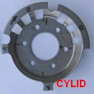


Bookmarks