
 Cantry Member
I’ve finally come up with a bolt in solution for the rear subframe froward attachment issue that the e36 suffers from. The forward attachment point box section is quite weak and can flex upward significantly under acceleration. The flexing eventually leads to popped spot welds and cracks hidden under the black tar sound deadening under the rear seat bottom cushion. Obviously once the spot welds have popped and cracks are there the front of the rear subframe can move up and down even more.
It’s an easy solution if you have a race race with a full cage, you can tie the cage into the rear subframe attach points and your done. For street cars with full interiors it’s more of a challenge to strengthen that forward attach area. I’ve cut the rear floor and shock tower section out of a wrecked M3 so that I could dissect the trouble areas and design a fix that can be bolted in. I have completed the reinforcement brace that fits between the floor and the rear subframe. Next will be a bolt in V-brace that will attach to the floor just behind the rear seat and tie into the rear shock tower area. The V-brace will get rid of any remaining flex if there is any.
I have been fighting this issue for some time. I found popped spot welds a year ago, fixed all the damage and added extra rosette welds to beef it up. Even after all that, a GoPro under the back of the car revealed that the rear subframe forward attach studs where moving up 1/2” with a brisk clutch release from a stop (not dumping the clutch).
Here is the reinforcement brace....
More to come......
Last edited by chikinhed; 03-26-2018 at 01:34 AM.
BFC Fire Marshal
in for the go pro video
98 Fern Green M3/2 - Precision 6870/AR Designs Twin Scroll/RK/E85
2017 Toyota Tundra Crewmaxx - Family Whip
2011 Pierce 75' Quint - Fire Apparatus West Islip FD
Cantry Member
I test fitted and made minor adjustments to the brace in the M3, drilled the holes and bolted it up. It fits great. The plates for inside the trunk are cut and just need to be drilled. I hoped to get the V-brace made today but ran out of time.
Last edited by chikinhed; 05-19-2019 at 01:05 PM.
Sleeps with his eyes open
I see no pictures. Currious to see where you're attaching at the body. I've been considering something similar.
Cantry Member
The pictures are there using the mobile version of Bimmerforums.Originally Posted by Kevin325i

Im still bitter about Photobucket screwing the internet.
The brace bolts to the angled face between the two forward attach points for the subframe and to the floor just behind the rear seat backs. Ive made up plates that will go inside the car that spread the load out for the though bolts.
Member
I don't see pictures either... not even sure how to use mobile version of BFC (nor would I want to lol).
Any chance you can fix the images?
Thanks!
Member
Yea pictures are not working.
Member
Are you going to be selling these?
Cantry Member
Ill see how much time I have into the whole thing. Designing and building the first one has taken a bunch of time so far and I also will want to beat on the car with it installed, I mean test it, before selling any.
Ive got the V-brace half done and a few other bits made tonight.
I redid the pictures, are they working yet?
Member
I can see pics. Cool design and fitment btw!
Sent from my iPhone using Tapatalk
Sleeps with his eyes open
I see no pictures still.
I feel you on the photobucket dicking. I haven't posted any more pictures of the steedspeed 2.0 that would probably help people because I have no good hosting service.
Cantry Member
Last edited by chikinhed; 03-11-2018 at 02:10 PM.
Lead Disagreement Eng PE
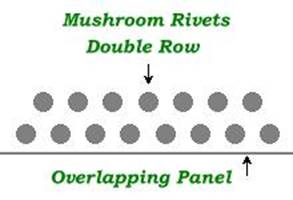
Cool idea. Have you thought about extending the outer two fastener rows farther out to give everything more stability? The bracket is super strong, but you're only grabbing the sheet metal ~1.5" from the bend. if you went out farther, and used a fastener pattern to give it more resistance to bending, you would gain more rigidity.
Something like this (but spaced out more on say a 3-4" long reinforcement sheet):
You would probably also need to make the plate they're mounted to stiffer in bending as well by running 1 or 2 stiffening ribs down it, but it'd make the whole area extremely stiff in bending.
Cantry Member
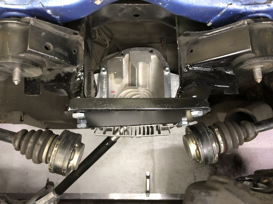
Thanks for you input Def. A second row of bolts would be a better choice but they are just going through the unsupported floor sheet metal. The brace is sandwiched between the subframe and the floor when everything is installed. I have made three doublers that go on top of the floor as the floor is not flat. The center doubler will remain on its own, the two outboard doublers will have the V-brace (still under construction) welded to them. The forward V shaped piece with the two bolt holes attaches to the tunnel between the forward subframe attach points and stabilizes the forward side. When the subframe front tries to lift under torque, it is restrained by the brace, the brace runs from frame rail to frame rail reducing the upward flex substantially. The outside edges of the frame rails and the forward and aft ends of the frame rails are connected to fairly solid structure but the inboard side is only connected to the unsupported floor. The V-brace will offer additional support to the brace if the inboard side of the frame rail does allow any flex.
The forward trunk floor and floor under the back seat are really flimsy in the e36. The box section with the two forward subframe attach points has to narrow down very thin to accommodate the driveshaft and it creates a flex point in the box section. I ended up with a five inch long crack in the floor at that location due to the flex. I'm sure that if people started to poke around in this location more of the cracking and popped spot weld reports would show up online. You have to actually look for the hidden damage though.
There are some compromises to the design do to space constrains under the back of the car and trying to keep it more of a bolt in design. Tube framing the back of the car is always going to be the best answer, I'm just not ready to give up my car as a daily driver.........yet.
'97 M3, Estoril blue, 2 dr, euro 6-spd, EFR 9180 divided T4 .92 IWG, RK tuning, CP 8.5:1 pistons, Eagle rods, Schrick cams, L19 11 mm ARP studs, O-ringed block, Supertech stainless/inconel valves, Supertech springs & Ti retainers, ported head, S54 oil pump/pan, 80 lb. injectors, OBD1 intake manifold, Steedspeed twin scroll T4, 3.5" SS exhaust, eBoost2 EBC, HFS-4 W/M injection, AEM Failsafe, Zeitronix data logger, Racelogic TC, OpenOBC w. ethanol %, Ireland Eng. engine mounts, UUC black tranny mounts w. enforcers, UUC twin disc feramic, ARC-8's, MCS 2-ways, Z3 rack, Rallyroad strut bar, X brace, Eibach sway bars, Ground Control LCAB bushings, Bimmerworld RTAB's, Powerflex subframe bushings, 210 4-clutch LSD, Stoptech BBK, titainium shims, steel braided lines, brake cooling ducts.
Member
Pictures are working on the tapatalk app. Looks cool.
Sent from my SM-N950U using Tapatalk
Cantry Member
I finished up the brackets that go under the back seat and the v-brace. Im pretty happy with how everything fits. Both the v-brace and plates unbolt. The tubes in the lower plates bolt to the tops of the forward subframe attach bushings.
Last edited by chikinhed; 05-31-2018 at 01:04 AM.
Member
I dont want to clutter things up but i couldnt find perrys (excellent)post on anti-dive and you (chickenhed) appear to be doing some work that may benefit.
I have been studying suspension setups for RC cars. My kid is getting into it and I learned more about getting a car setup to do something specific on a particular type of track and by the way its all about traction. Traction comes from setting up the suspension to move or minimize movement of weight to keep a tire or pair of tires in there sweet spot for load.
I cannot disagree with perry in any way shape or form and specificly about the rear suspension drawing the rear wheels up into the chassis (e36) on accel. But on the front suspension having the rear (front subframe) lower than the rear (front subframe) limit the amount of weight transfer from front subframe to rear and it also works in the opposite direction (limit that topic to accel if its worth talking about.
during braking you can do the same but adjust the rear subframe to control dive.
of course caster angle changes if you shim a subframe but for example raising the rear of the front subframe to minimze weight transfer to the rear also takes some of the oversteer out of the front and vice versa.
Ok yea, its based on RC cars but there is a software package that you plug in the suspension geometry into and it calculates CG, roll center, ride frequency, roll coupling, dynamic loading... I cant even begin to explain all this thing does but one thing I learned that seems to be at odds with the static camber numbers i had set in my car in the rear. Something close to 0 so that i had max traction in a straight line. As the rear suspension is sucked up into the chassis and the geometry does its thing the arms force camber gain. Probably in the order of 2 degrees or so from static to full tuck. If im at 0 static and launch doesnt camber go positive?
its easy enough to measure with a level and your rollbar and springs decoupled. Can you check it out if your still working on it chickenhed? From ride height to compressed the change in degrees?
one thing i found insane is that if i jack the LR corner of my car up until it lifts the LF and compare it to the same on the right hand side i can account for why my car corners one way better than the other or pulls right during accel and the ride height was perfect all the way around.
Cantry Member
As I put it back together I can do a camber check from full droop to bottomed out and see what I get. I would also like to do the same and measure toe but Ill have to hit up a buddy to use his alignment rack for that.
I remember Perrys thread about antisquat. It inspired me to do a bunch more reading on it. My rear control arms do angle upward towards the rear which will give squat under acceleration. The guys that drag race end up jacking up the rear suspension so they can get clearance for drag radials which corrects the angle so they dont have the same issues with hop as a result. The sidewalls are softer and that helps as well.
With the rear wheels being lifted and the rear subframe forward attach point flexing upward, no wonder I get bad wheel hop. Once its back together Ill do some launches and see what affect the reinforcements have done. Then Ill try raising up the rear to see how that affects it. I intend to win this hop battle.
Last edited by chikinhed; 05-19-2019 at 01:19 PM.
Cantry Member
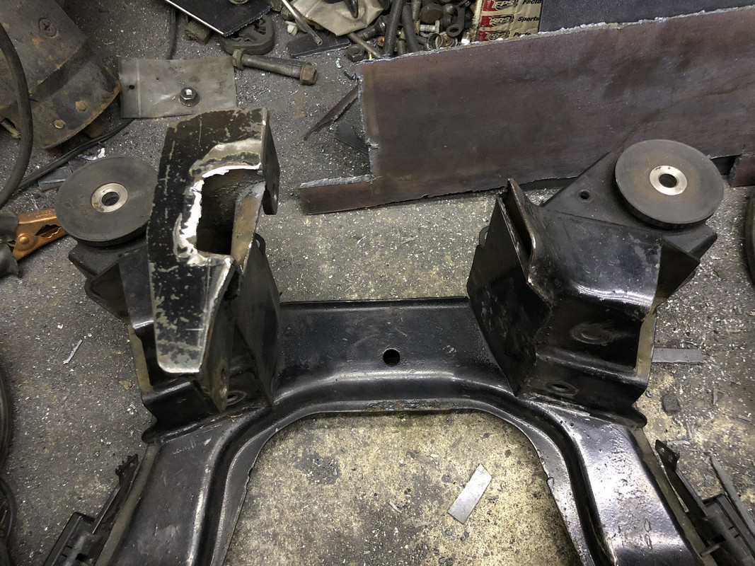
The next mod is to mod the rear subframe to make removing and installing the 210 diff much easier. This should have been part of the CES 210 conversion kit to begin with. Ive cut the bottom center out of the subframe, now I just need to cut out the pieces to weld and bolt in. I cant wait to assemble everything.
Last edited by chikinhed; 05-31-2018 at 01:00 AM.
Member
Cool. One method of minimizing on throttle weight transfer from the front of the car to the rear of the car is to put 2-3 degrees of angle (front up...rear down) on the rear arms. Im not sure you do or dont want want that weight moving towards the rear but the flex was doing it if you had that much flex.
I dont know if it applies to our cars but i have noticed on a couple cars that its allot harder to move the rear arms up if camber gain is close to 0 (lengthening camber arms). The other thing I read but havent tried is that at ride height the axle angle will either push or pull the suspension in one direction or the other.
thanks man. Interested to hear what kind of camber gain you see which I believe causes toe and caster changes but within reason.
Cantry Member
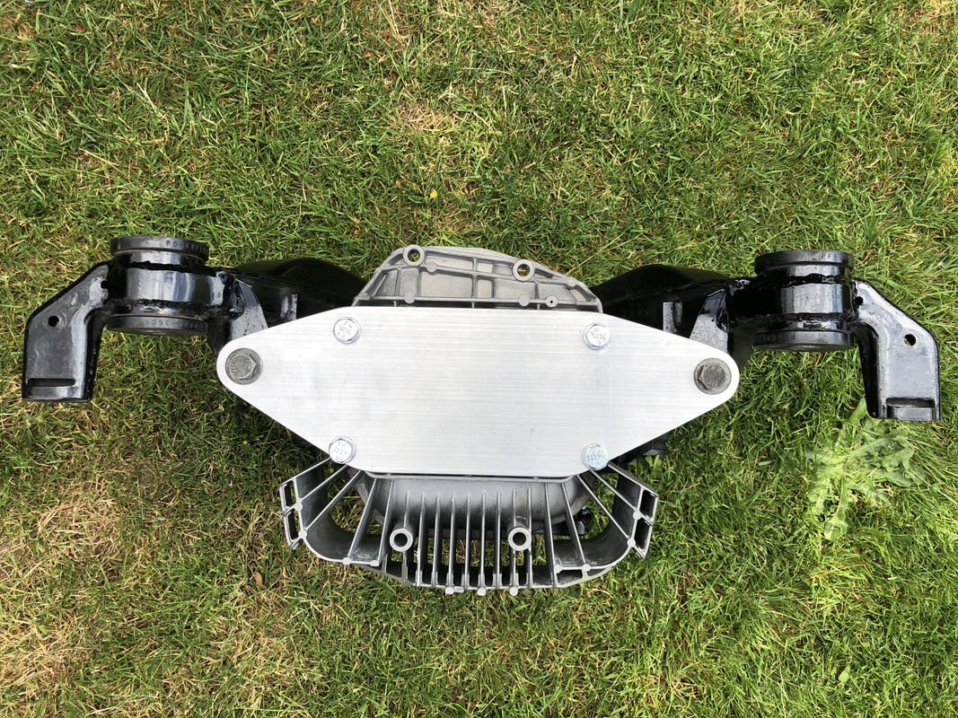
Very slow progress this time of year but I received an e46 M3 finned rear diff cover to try and keep the diff cooler when on the track. It bolts in to the 210 diff as expected but the position of the mounting ears puts them in the e36 subframe. I was hoping to just relocate the subframe mounting points but thats not going to happen. The other issue is no provisions for the VSS but that wouldnt be that hard to sort out. Back to the drawing board...
Ring Master
If you want when youre done I can digitize one of these and have a set of like 25 run pretty easy.
I have been thinking about doing something like this for a while. Looking at Randys kit a while back always had me thinking.
Sent from my iPhone using Tapatalk
1989 535i - sold
1999 M3 Tiag/Dove - sold
1998 M3 Turbo Arctic/black - current
2004 Built motor TiAg/Black - Sold
2008 E61 19T Turbo-Wagon - current
2011 E82 135i - S85 Swap - current
1998 M3 Cosmos S54 swapped Sedan - current
1998 Turbo: PTE6870 | 1.15 ar | Hp Cover, Custom Divided T4 bottom-mount, 3.5" SS exhaust, Dual Turbosmart Compgates, Turbosmart Raceport BOV, 3.5" Treadstone Intercooler, 3.5" Vibrant resonator and muffler, Arp 2k Headstuds | Arp 2k Main studs | 87mm Je pistons | Eagle rods | 9.2:1 static compression, Ces 87mm cutring, Custom solid rear subframe bushings, Akg 85d diff bushings, 4 clutch 3.15 diff, , Poly engine mounts, UUC trans mounts W/ enforcers, 22RPD OBD2 Stock ECU id1700 E85 tune, 22RPD Big power Transmission swap w/ GS6-53
Light Fires N Burn Tires
That looks great!
Cantry Member
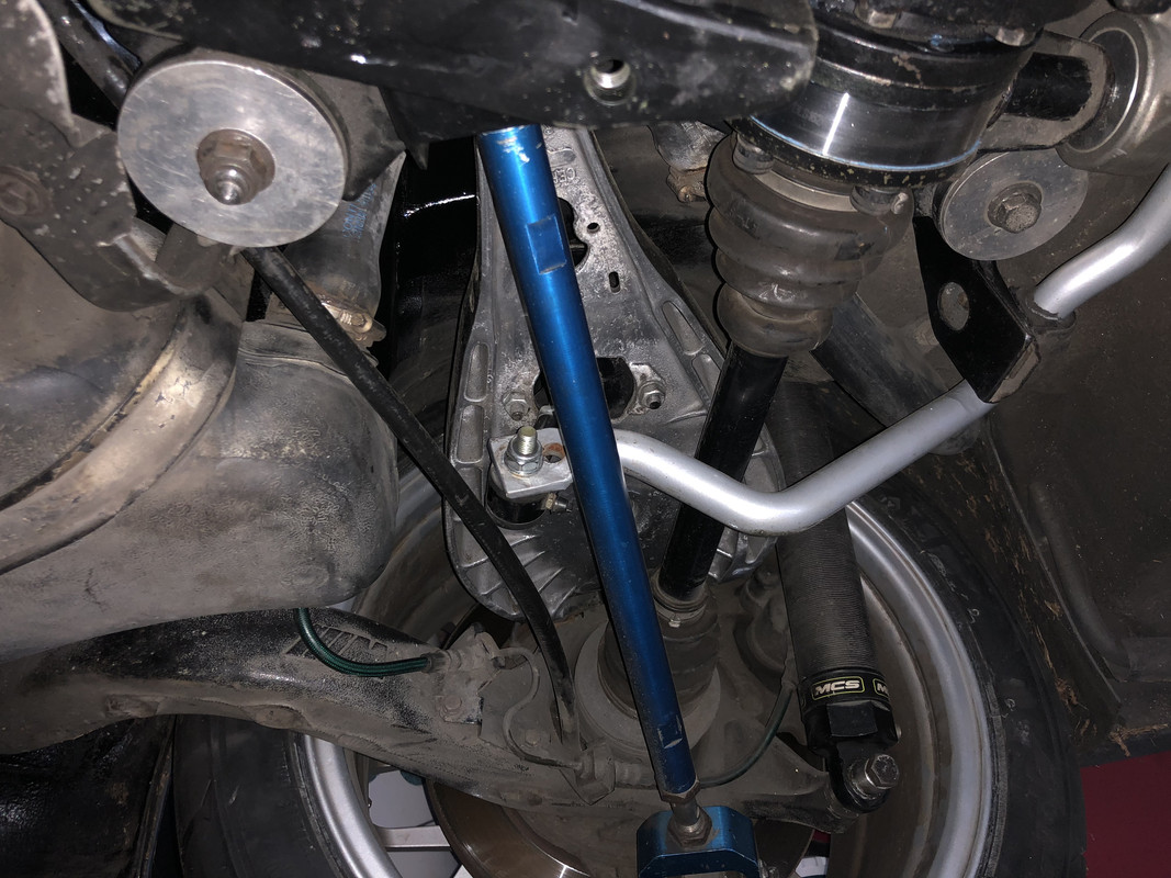
I finally got the reinforcements installed along with the subframe, suspension, diff and gas tank. Im also halfway through modifying an e46 M3 finned diff cover for the 210 diff in the e36 subframe.
I still have a bunch of stuff to do but at least I have some progress.
Last edited by chikinhed; 05-29-2018 at 08:48 PM.
Cantry Member
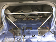
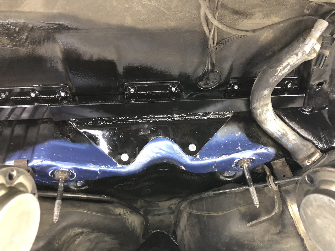
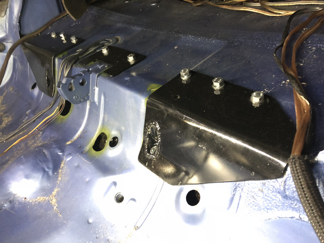
Interior reinforcement plates are bolted through the floor into the brace. The brace is sandwiched between the subframe and the floor. The plates will be hidden by the back seat and carpet.
The Alan head bolt connects the plate to the top of the fitting that the rear subframe forward studs thread into.
The gas tank, subframe, suspension and diff are back in. Installation was much easier with the center section removed from the subframe.
Last edited by chikinhed; 05-30-2018 at 03:55 AM.
 Posting Permissions


 Reply With Quote

Bookmarks