
 Disco Librarian
Legion,
I have purchased the usual ignition upgrades including an ignitor unit, red coil, AR 52 plugs, and 8mm wires. My current coil looks like: Looking at the wiring diagram the red/black wire is a non ballast bypass that connects to the starter and is only powered when the starter is cranking
The black wire with the yellow wrap runs to a green ballast wire (somewhere in the bundle) and into the start run bus. While the set-up can work with the ballast wire it makes much more sense to run a new wire from a 12v switch source that gives the full "juice". Where is the best place to tie in? I would prefer to use a disconnectable terminal, to allow for the possibility of reverting due to failure, or need to return to factory original status when my car is determined to be the most collectable vehicle of all time.
-Roy
Member
Here's the wiring diagram - http://jtresto.com/e21/ETM_1977.pdf
Shows the ballast wire on page 4-3. It is labeled gn which I think is yellow-black, and labeled ballast 0.9 ohms.
So I'd replace that, just disconnect it and leave it inside the harness, and install a red wire in its place and zip tie it to the outside of the harness. Remoave the black/red wire from the sTarter.
Member
Last edited by okieflats; 03-09-2017 at 01:33 AM.
Member
I looks like in order to eliminate the ballast you may be able to just bypass the part of the GN wire that goes from the diagnostic connector to the coil, and leave the rest of it intact.
http://jtresto.com/e21/ETM_1977.pdf
page 4-12 in the wiring diagram says it is pin 2 of the diagnostic connector that is the start-run bus, that would be the GN wire. Pin 2 is the bottom center pin in the diagnostic connector. You could test it with a voltmeter. Does it go to +12v when the key is turned to on/run? So you could run a wire from there to the coil, and disconnect the GN ballast wire at the coil, and you'll have bypassed the ballast.
Member
Just fyi:
The ballast wire is 0.9 ohm/meter. If it's original, it's in marginal condition. This ballast wire's insulation is black (and falling apart) and connects to the Green start/run bus wires next to the starter motor. There's a small bulge on the harness wrap where the ballast wire is connected to the Green wire(s). It will be very difficult to keep the wire harness 'looking' original if you decide to replace the ballast wire completely.
If the instructions for the new ignition components require a ballast, I suggest trying a ballast resistor wire from a '65 ford mustang, *between the diagnostic connector and coil as Okieflats mentioned. This way you can preserve the originality that you desire. If the instructions do not require a ballast, just run a 12g 'fine strand' copper wire with soldered connections between the diagnostic connector and coil. Make sure the diagnostic connector is clean/tight and use silicone grease on the connections.
Ford ballast wire:
*may have to solder/connect a length of copper wire if it's not long enough...
smp-rw34t_ml.jpg
Some folks have used a ceramic type ballast (such as myself), but this requires drilling a hole, mounting, etc...
Here's the location where the OE ballast wire connects to the Green start/run bus:
(disregard the wire-nut, this was not my doing)
ign-resistor-wire-bad.jpg
*With the new/upgrade ignition components, you probably will not need to use the Black/Red resistor bypass wire from the starter motor solenoid. So, just keep that in-tact, but disconnected from the coil.
Last edited by epmedia; 03-09-2017 at 04:27 AM.
Tbd
Disco Librarian
Thanks for all the responses. My understanding is that the ballast is there to protect the points and that when using the red coil and Pertronix unit it is better to remove it.
This sound like it might be the best option, even if i won't look completely factory it will avoid the level of fail from EP's picture. How hard is it to de-pin a BMW connector, and is there any special tools required>Originally Posted by okieflats

mumbler
Please detail what you do. I used the fake Pertronix kit from eBay ($50) AND the Pertronix flame thrower coil. It was pretty much, a direct-on, the only fuss was trying to figure out why one magnet sleeve would not work and the other did (they are different heights). However, I had another magnet, from another kit that was the same size as the one that did work; it would not fire.
Also, there's the wire that has nowhere to go once you start this on our '77's (maybe that is the ballast wire??? It never went to the coil, it has a female clip on it), I had to tape it up because, it would stall the car, or prevent it from starting at all when it touched...anything metal.
I may need to take a picture to express myself here.
Of course, I DID use the cheaper HOT-SPARK version, P-tronix may be a little different. Point is, I'd like to know if I'm not getting all the juice that I should be getting. Thanks.
Member
pic please....
mumbler
of mine?
Disco Librarian
I believe the wire you are referring to was connected to the condenser. I will post some pictures when I've completed to conversion, but the simple explanation is I'm bypassing the ballast wire, while keeping everything as tidy as possible.
Disco Librarian
I completed this update today, and have to say I'm quite pleased with the result! Seat of the pants feeling is there is more horsepower, but the biggest difference is how easy the starts and climbs through the revs. I will say I also replaced the ignition coil, which could also have some effect. I would like to make a note of the fact that once the ballast wire is bypassed you cannot simple replace the Pertronix unit with the original points should it fail. This is why I chose to leave the original wires in the harness in case it proves unreliable.
As for how to bypass the ballast wire, it is fairly easy even for a wiring novice like me. As shown below the central green wire (8) on the wiring connector can be trimmed shortly after the plug.
C20h.JPG
I just trimmed off the first foot or so of the bundle wrap, but if you wanted to you could remove the entire thing and re-wrap it. Additionally the red/white wire that goes from the starter to the positive terminal on the coil can be removed/disconnected. I removed the battery, and airbox (requires the top of the AFM to be removed as well) to allow for easier access, and would recommend anybody else do the same. Finally get some good tools and connectors. I bought solder filled fully insulated terminals from McMaster Carr and the quality was noticeably better than the cheap auto parts store variety. Tools Used to create and verify connection shown below.
Wiring tools.jpg
I'd be happy to answer any questions.
Member
I'm working on bringing my 1979 320i back to life. It had a bunch of issues related to stagnant fuel and a bit of monkeying around had been done to the ignition system by the previous owner in hopes of getting it running. In an effort to get it running again, I've tried my best to replace any of the questionable work he'd done and get as close to stock as I could(I'm new to futzing around with cars and stock is what I can find the most information on). I'm currently running points with Red Bosch Coil, Bosch WR9DC+ Plugs, new Bosch rotor, new Bosch cap, new old stock Bosch wires, and a new condenser. I've got it running again, but I still need to replace the ballast resistor.
I'm wondering just how long the factory resistor wire is? Where should I look for the joint from the Black resistor wire to Green wire? Prior to the condenser break in the wiring loom? Splicing in a section of straided green wire at that joint seems like the cleanest solution to me. I'd run the new green wire to ceramic 1.8ohm resistor from there and then to the coil.
Long time reader, first time poster...
Disco Librarian
I bypassed the harness for now, trimming a few inches out of the fuse box. If you pull out the fuel distributor/airbox out you can feel along the bundle for the thick spot where the resistor wire was soldered in.
Member
Thank you! Ill see if I can feel it down there.
Member
If needed, Post #5 has a pic for reference, click to enlarge.
Tbd
 Posting Permissions


 Reply With Quote
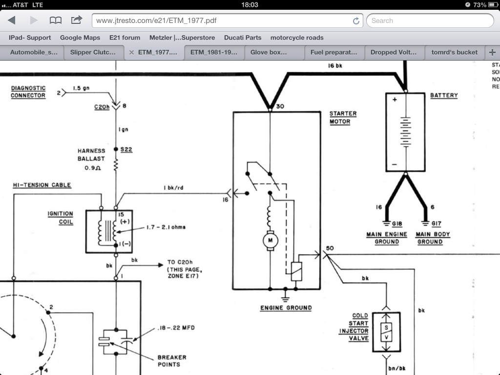


Bookmarks