

 Member
Hoping you guys may be able to help me out with something.
I've just bought a Tilton 3 pedal floor mount box for my S54 E36. I've also bought the throttle linkage for DBW, which uses a Penny & Giles TPS280DP. I've checked out all the voltages etc, and they all tally up fine with the S54.
I'm looking to understand how I take the new sensor that is a 4 pin connector, in to the MSS54 harness which has a 6 pin.
These are the connections on the new tilton DBW:
Red : +V Supply
Black: 0V Supply GND
Yellow: Ch1 Output
White: Ch2 Output
From my current research my BMW accelerator has the following pinouts:
Pin 1 - Ground
Pin 2 - Ground
Pin 3 - Electronic pedal
Pin 4 - Electric pedal
Pin 5 - Voltage supply for electric pedal
Pin 6 - Electronic pedal
At the moment I'm assuming its:
Red - Pin 5
Black - Pin 1/Pin 2 Ground
That leaves me with 3 more pins left to deal with to pick up the remainder of the connections. Anyone have any ideas?
Member
You may want to look at the pedal sensor out of a MZ3 Pn#13621407446. The pedal sensor is those cars are not built in the pedal like the M3, but retrofitted to a standard pedal.
No. Description
1995 BMW M3
Avus Blue 10/95
Member
Here are the pins along with the labels for the DME connections from WDS:
1 - Ground Pedal-position sensor Pedal-position sensor
2 - Ground Pedal-position sensor Pedal-position sensor
3 - Voltage supply Pedal-position sensor Pedal-position sensor
4 - Signal Pedal-position sensor Pedal-position sensor
5 - Voltage supply Pedal-position sensor Pedal-position sensor
6 - Signal Pedal-position sensor Pedal-position sensor
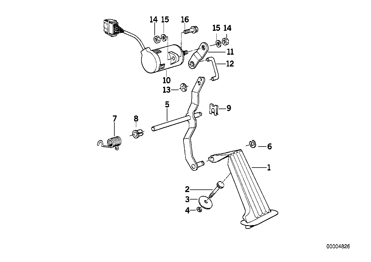
And this shows the internals of the stock pedal:
Capture.PNG
Sounds like your yellow/white need to connect to 6 & 4. Are you sure the output is compatible? Per WDS:
The pedal-position sensor or accelerator pedal module is powered by an exact voltage of 5 V from the DME control module. The pedal-position sensor or accelerator pedal module is equipped with two completely independent, mechanically coupled sensors. Both sensors output a voltage signal corresponding to the current pedal position. For safety reasons, two sensors are used in order to determine any faults. Sensor 2 always generates exactly half the voltage of sensor 1 so that a short-circuit of both sensors can be detected.
If so, I'm guessing you can connect red to pin 5, and black to pin 1. The DME may not be happy with the connections to pins 2 & 3 floating. If so, I'd measure the resistance of the stock pedal across those pins and bridge them with a resistor of the same value.
S54 swap DME flashing - $100
S54 swap CAN interface board (for proper A/C & check engine light) - $275
e36 SAP sim/secondary air pump simulator: $75 - standard or $170 - plug & play
e36 post-cat O2 sims: $115 shipped, plug & play
Member
Great stuff, thank you very much for the responses. As far as I understand it both of the voltage outputs from the Tilton sensor behave identically to the BMW fbw pedal.
I'm at the Autosport show start of Jan where everyone will be and will run it past the guys on the Tilton stand, and the manufacturer of the sensor that they are using. Will report back on my findings.
Member
I just bought the cylinder shaped Z3 M sensor and I will try to fit it to Tilton 600 series pedals. I don't have to have compatibility with any ECU's, I will just take the voltage readings from pedal sensor and use those to PWM drive propably E46 M3 throttle body servo motor with my own module. Engine is M42 with S50B30 ITB's.
I tried to find info what is inside E46 M3 DBW pedal, some sort of Hall sensor setup I guess, but no luck.
Member
Boyracer did you have any joy using the Z3m potentiometer setup with the tiltons? My build took a bit of a back seat but I'm about to get back on to it.
Member
Now i've finally cracked a solution I thought i'd share it with anyone considering the same.
The first issue I discovered was that the MSS54 ECU looks for a couple of things on the stock accelerator pedal to verify that it's working correctly. It has a failsafe where it compares two voltages against each other as the throttle changes position to enable the detection of a fault.
Using the Tilton 600 series pedal box they do have a fly by wire throttle linkage and throttle position sensor add-on, which I originally bought only to find out the stock ECU would not be compatible with it. I even explored creating a controller which would modify the voltage signals to trick the ECU but that ended up being a dead end.
As above I took the E39 M5/E36 Z3M S54 throttle potentiometer which was separate to the pedal. Having spoken to my fabricator, he managed to find a way to create a bolt on adaptor for the potentiometer. Works an absolute treat.
Wiring wise, it uses the same 6 wires as the existing pedal, although the plug is different. I just ran in to a tyco 6 way connector on both sides and that was it. Works perfectly, reads correctly on INPA!
Some pics here:

 Posting Permissions


 Reply With Quote


Bookmarks