
 Member
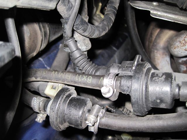
There are 2 tank vent valves located at the front of the engine close to the AC compressor. Each has a hose to a 'T' going to the charcoal canister and another to one of the throttle bodies (see diagram attached)
The manual clearly shows how the vacuum lines are routed but does not detail which of the wiring harness connectors goes to valve #1 and which to valve #2. There is a black connector and a white connector.
My question is which connector to which valve?
ventvalves.jpg
Thanks!
Member
Black to #1
White to #2
Last edited by rogbmw; 11-28-2015 at 08:49 AM.
CSi #18 - Car & Driver Magazine 1994 actual test car
-- Hellrot/Black-Gray (1 of 1 NA CSi color combination)
BMWCCA E31 Chapter International Clubs Liaison
North America Representative, 8er.or Board of Directors
Member
Thanks Rogbmw.
I put together a cheat sheet with pics copied from the manual but not sure this is right yet... (confirmed not correct - see later post)
BMW 850i connectors.jpg
The diagram at the right which I copied from the manual shows tank vapor vent valve cyl1-6 connected to throttle valve assy cyl 7-12 which is obviously not correct!
I'm guessing the vacuum lines to the throttle valves are crossed so I corrected them in the diagram. This would make sense because then all the connectors for cyl 7-12 are white and cyl1-6 are black.
Could someone confirm the vacuum line routing from the tank vent valves to the throttle bodies is as I have shown?
Last edited by BMSman; 11-29-2015 at 12:33 PM.
Member
I will add that the factory even added a white cable tie to denote the one for the white connector. Crafty buggers they are! (see pics above)
By the way, I am not sure if routing technically matters. I am not saying it does not, its just that my understanding is that they are closed when the vehicle is running. But as the above as examples, the black connector ones goes to driver bank. White to passenger. Like many duplicate items on the car, the cables or hoses are a hint based on length or position. Once you see that pattern, its more obvious in how they did some stuff.
______________________________
1992 750iL
Member
I just went out to reverify -
BLACK connector = Driver's side bank.
WHITE connector = Passenger's side bank.
So what you have in green and yellow is incorrect.
I have everything off the front of the motor - Fan, fan clutch, radiator, shrouds, etc, and can see directly where everything is attached.
CSi #18 - Car & Driver Magazine 1994 actual test car
-- Hellrot/Black-Gray (1 of 1 NA CSi color combination)
BMWCCA E31 Chapter International Clubs Liaison
North America Representative, 8er.or Board of Directors
Member
OK I think I got it now. My theory about the black and white connectors proved to be wrong. Drawing in manual is still labeled incorrectly.
Please take a look and let me know? You might also confirm that the 2 lower connectors under the oil filler cap are the white ones?
BMW 850i connectors ver2.jpg
Last edited by BMSman; 11-29-2015 at 12:36 PM.
Member
That last drawing is correct. Which also means the manual is correct.
______________________________
1992 750iL
Member
FYI check those tank vent valves for leaks. When I did a smoke test they were both leaking badly. Test them they should hold vacuum. If not, I used some q-bond around the seam to seal them. This can be a pretty major source of vacuum leaks since they connect directly to the DK motors vacuum port.
1987 L6
1997 840ci
2000 740i Sport
2000 M Roadster
2001 M5
2002 540i Sport
2002 X5 4.6is
2003 530i Sport
2003 M3
2003 Z3 3.0
2005 X5 3.0 Sport
Member
Items 3 and 4 are labeled incorrectly (1-6, 7-12 switched)Originally Posted by unity

- - - Updated - - -
Thanks. I'll check this.
Member
Okay, I was not looking at that I was just looking at the diagram.
______________________________
1992 750iL
Member
For the tank vent valves, both are normally closed when driving? When do they open?
I used DIS5.7 to test both of mine. Cylinder 1-6 is the top vent and it cycles when I activate it. You can hear it and feel the device moving inside
Cylinder 7-12 vent does not make a sound or move anything when activated so I'm assuming it's broken. I have a spare I believe that I can swap in and see if it works.
Sent from my Nexus 5 using Tapatalk
Last edited by clockwork; 08-03-2017 at 11:42 PM.
I swear, my cars are like a girlfriend.
Sometimes its a rough ride, sometimes its smooth motorin'.
Sometimes she doesnt like how i treat her and sometimes i dont like how she behaves.
BUT at the end of the day, she loves it when I am inside her.
shade tree mechanic
Moderator
For a quick test: the tank breather valve should have a resistance of 45 +/- 20 Ohm and it closed without 12V power.
German description from the BMW testing instructions for M1.1: Pruefanleitung DME 1.1:
Tankentlueftungsventil (TE-Ventil) pruefen: Das TE-Ventil wird im Sekundentakt angesteuert. Die Taktung ist mit der Hand fuehlbar.
Dichtheit pruefen: Unterdruckversorgung vom vom Service-Tester am 8-mm Anschluss anschliessen (Durchflusspfeil beachten). Unterdruck auf 600 mbar einregulieren und TE-Ventil mit 12V versorgen. Unterdruckpumpe abschalten, nach 20 Sekunden darf der Druckabfall 50 mbar nicht uebersteigen. Im stromlosen Zustand ist das TE-Ventil durch ein Rueckschlagventil bis zu einem Saugrohrunterdruck von 20 mbar geschlossen.
Ansteuerphasen pruefen: Das TE-Ventil wird im Leerlauf angesteuert (Anzeige EIN) und ist somit geschlossen. Sobald die Lambdaregelung aktiv ist und die Drehzahl bis ca. 1600 UPM erhoeht wird, kann die schrittweise Oeffnung beobachtet werden (Anzeige AUS).
translated: From test instructions DME 1.1:
Tank venting valve (TE valve) check: The TE ( TE = Tank Entlueftung = tank breather valve) valve is activated every second. The clicking one can feel by touching the valve by hand.
Check tightness: Connect the vacuum supply from the service tester to the 8-mm connection (observe flow arrow). Adjust negative pressure to 600 mbar and supply TE valve with 12V.
Switch off vacuum pump, after 20 seconds the pressure drop may not exceed 50 mbar.
In powerless state the TE valve is closed by a check valve up to a suction pipe vacuum of 20 mbar.
Check driving phases:
The TE valve is activated in idle (display ON) and is thus closed. As soon as the lambda control is active and the speed is increased up to approx. 1600 rpm, the stepwise opening can be observed (display OFF).
Shogun tricks and tips for the E32 series are HERE!
Member
sorry for my dumb question , but what is in fact the use of that complex system compared to just let the tank vent open with a air filter on it ?
It's only for emissions i suppose , not venting fuel vapor to air as common in older cars ?
And there are 2 valves…. just to share the A/F influence over both banks ?
shade tree mechanic
Moderator
All modern cars are equipped with an Evaporative Emission Control (EVAP) system. The EVAP system prevents fuel vapors from the fuel tank from escaping into the atmosphere.
Divided over 2 banks is needed, otherwise only one bank gets all that uncontrolled stuff. Here a copy from the web:
Fuel Tank Venting System
One of the subsystems in fuel distribution is fuel tank venting, which usually remains unrenowned because of its low priority in engine operation. However, the system shouldn't be dismissed, because there are instances where it causes some irregular issues.
A bit of theory
Sometimes unwanted fuel vapors appear in the fuel tank: in a heat wave, when the fuel splatters in the tank, and the surplus of fuel reappears from the fuel injection nozzles, or simply because of slight fuel evaporation. It's harmful to the fuel tank, to health and environment. For this reason, in recent decades fuel system in all vehicles has been fitted with a fuel tank venting system, which uses a carbon canister for absorption of excess fuel vapor from the tank.
Operation concept
The fuel pipe runs from the tank right to the carbon canister. Under the vapor canister, there is a hose that removes the water resulting from the venting process under the car's underside. On the other hand, the system is connected to the intake manifold via the bypass valve, which helps clean the carbon canister itself and facilitates more efficient usage of gasoline vapors. The bypass valve operation is controlled electronically.
When the car is in standstill, with the engine shut off, the bypass valve is closed and fuel vapors leak outside under their own pressure via the carbon canister. When the engine is running, the valve opens from time to time to intake air from outside for the system of absorber cleaning. In this case, the induction system receives extra air that is not taken into account by the air-flow meter. This opening of the valve also removes fuel vapors from the tank. For this reason, the bypass valve is configured to open on occurrence of certain conditions (revs) and can directly influence engine failures. In some vehicles, the bypass valve can be configured to perform air intake from outside and vapor intake from the tank one by one.
Issues
If the bypass valve is closed, it doesn't usually affect driving performance. However, sometimes, the internal diagnostic means of the vehicle may signal about engine fault. And the environment will be bitter about your car, because the absorber eventually gets clogged and removes fuel vapors from the tank without purifying them, which creates the stinky gasoline smell under the hood.
On the other hand, if the valve gets locked in the open position, the engine will constantly receive extra air that is not taken into account by electronics. This will create negative pressure in the fuel tank, which may affect the operation of weak fuel-oil pumps, misshape the tank or hinder tank cap opening. All this is not good, so you'd better completely choke up the pipe between the intake manifold and the carbon canister, or replace the broken-down bypass valve with a new one (they're pretty cheap, indeed).
here I posted for the E36 the training info: Evaporative System Monitoring, E36 TLEV Vacuum System http://www.bimmerboard.com/forums/posts/1268846/
Shogun tricks and tips for the E32 series are HERE!
Member
I want to re-do the wiring and vacuum lines on my '91 850i.
As I mentioned in my thread, someone chopped off factory electrical connectors, spliced wires and created 1 electrical connector, then they removed the 2nd valve and left only one installed.
Vacuum lines I can re-do easily.
Questions that I have:
Is there an alternative OEM purge valve? Part # 13901711395 / Bosch discontinued part number: 0 280 142 150
The ones from the dealer are pricey and ideally, I'd want to replace the existing one as well.
From previous posts we learned that black connector goes to cyl 1-6 and the white connector to cyl 7-12.
However, since connectors on my car are no longer there how do I know which one goes where and does it in fact matter? I assume that it does otherwise they wouldn't be labeled differently from the factory.
I have 4 wires to which I'm planning to install factory connectors and make sure they are getting power, but determining which one goes where is the question.
Member
are the wire colors the same for left and right ? that could be a way to found out ?
As Shogun kindly explained , it matters i think , as the bank sucking vapors must match with the O2 sensor seeing a changing AF condition…. IF it is so on our 850's ???
Member
I just bought two new Bosch 0 280 142 300, which fit perfectly (and are much cheaper).
Member
Good to know. Thank you!
Sent from my SM-G965F using Tapatalk
Member
Bosch 0 280 142 300 is not exactly a perfect match. Resistance is different and the valve opens and holds at different pressure when applied compared to the original valve.
Also, both ends are 8 mm in diameter while the original is 6 mm on the input side and 8 mm on the output side.
It fits and works, but not sure what kind of difference it will make, if any. Have you installed yours? Any problems with it?
Member
Yes I noticed the slight diameter difference at one side, but this is no problem for the original hose.
Regarding pressure differences, I guess since these valves are normally closed unless electrically opened, this is irrelevant.
Seems to works OK.
Member
Hi All and thanks for all the good info in this thread.
I am playing around with these valves on my 91 850i, seems that problems here can trigger a 1221 (2221) and/or 1222 (2222) stomp code.
What I have noticed is that either one of the valves connected to the white connector does not (by touch) open and close as strongly as when connected to the black connector. This is with the engine running.
Could there be some sort of "driver" relay/transistor/etc that gets weak causing the valve to not open and close correctly?
Also FYI, with my diagnostic tool (FoxWell NT510) it is not possible to remotely activate the white connector (i.e. it does not respond even weakly).
 Posting Permissions


 Reply With Quote
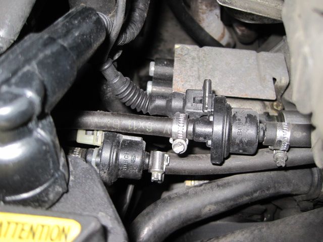

Bookmarks