
 M54B30 Inside
I have a spreadsheet that lists every segment of wire, what it is connected to, and how it is connected. Every trace is checked against the build sheet with a DMM during assembly, and after assembly.Originally Posted by Schitzo

I've also built a number of spare traces into every harness just in case I need to "fix" something, or add things at a later date.
- - - Updated - - -
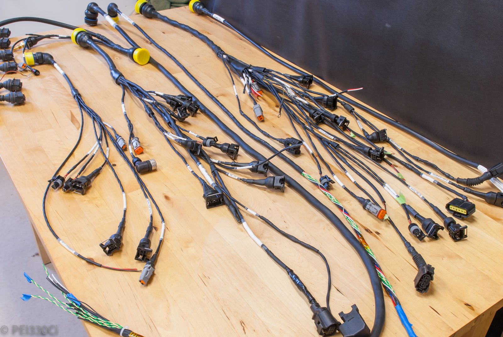
I ran out of supplies (connectors) due to a mistake in planning. I should get the next shipment of "stuff" tomorrow, but in the mean time here is where I'm at with harness construction:
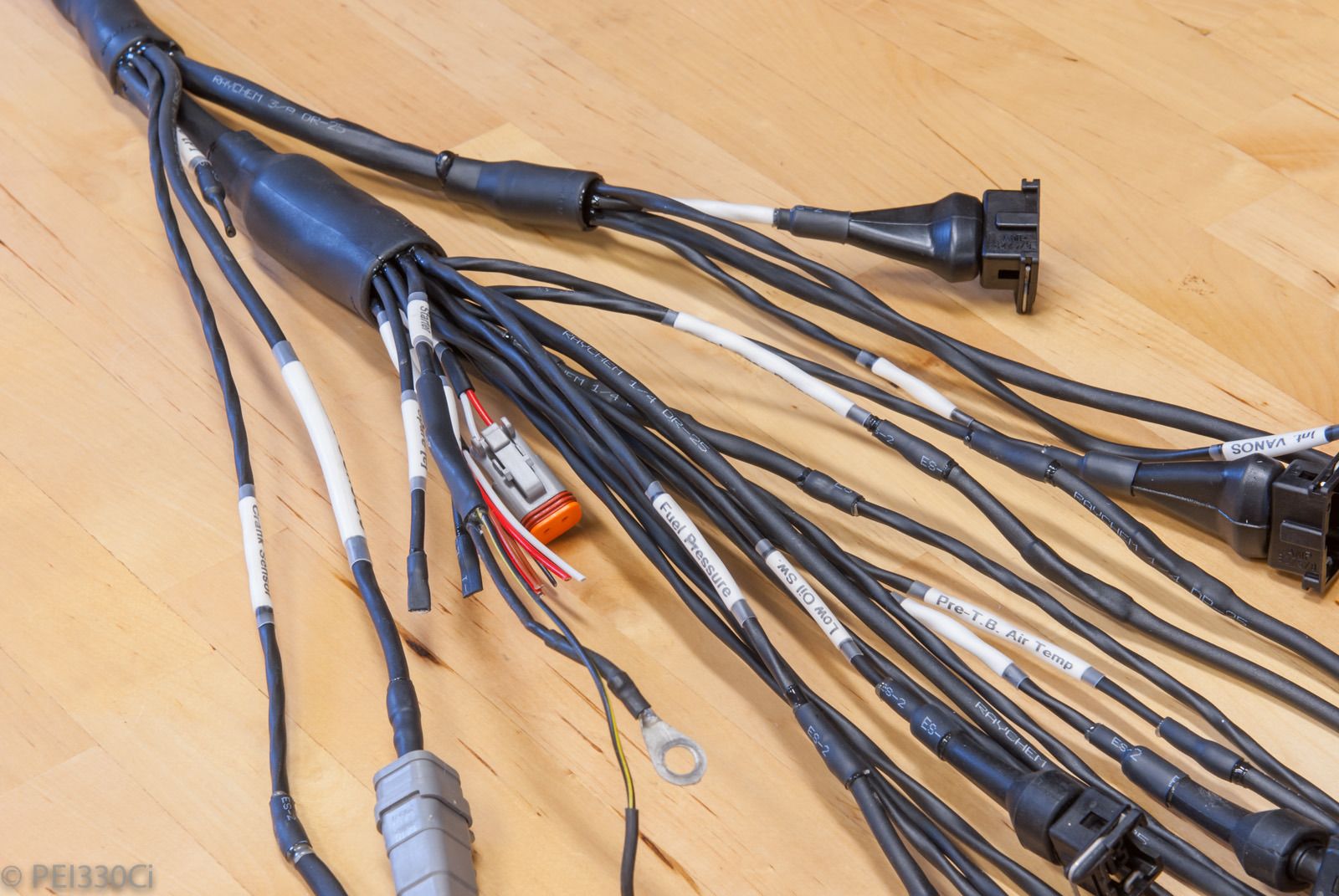
The left engine harness transitions:
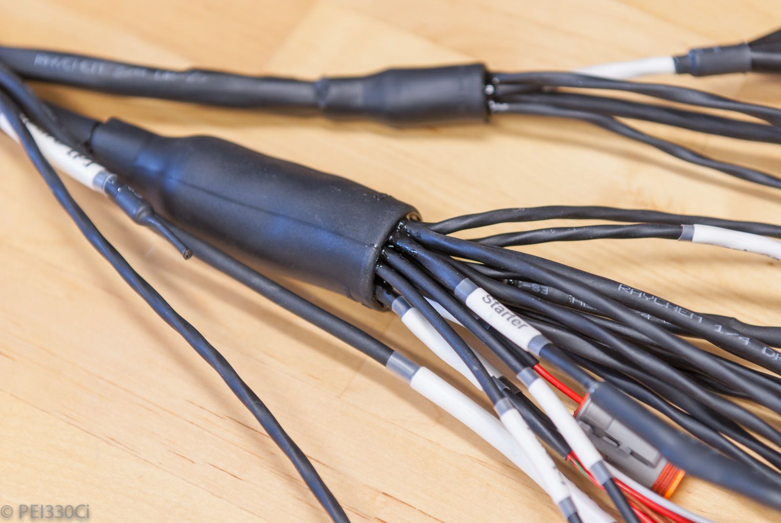
Giant "-63" Raychem transition:
Right side engine harness transition:
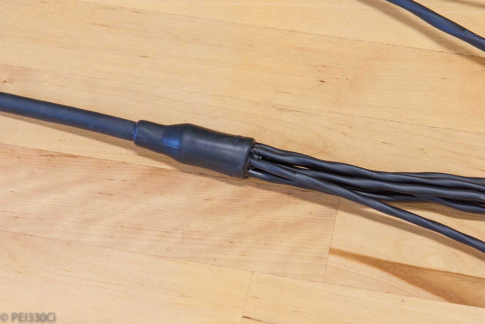
I thought this one was pretty cute:
4mm in, and 8mm out.
Yesterday I started working on the dash panel, and it's been more of the same today. Tomorrow I'm hoping to have everything buttoned up, and will post some pictures of what a mess I've made....
Member
Looks great
No deutsch connector boots though?
Edit - nm looks like only a few are missing
M54B30 Inside
Waiting for supplies...thus you'll also see some wires without any connector on them. DTM's are pretty easy to de-pin and add stuff with....
ßMW///MµrÐêr§þðr
You are a TEDIOUS creature.
Thanks for the harness pron. Inspirational.
Member
beautiful work! wow. I gotta ask though. why the resin instead of marine shrink tube? great work on the labeling.
M54B30 Inside
From a practical perspective: Glue lined heat shrink tube doesn't address the gaps between wires at the center of the bundle.
From an ego perspective: I gotz the same s**t as fighter jets under my hood, yo!
Member
Yeah they're very easy just wasn't sure if there was a reason for that
Member
definitely grade A
M54B30 Inside
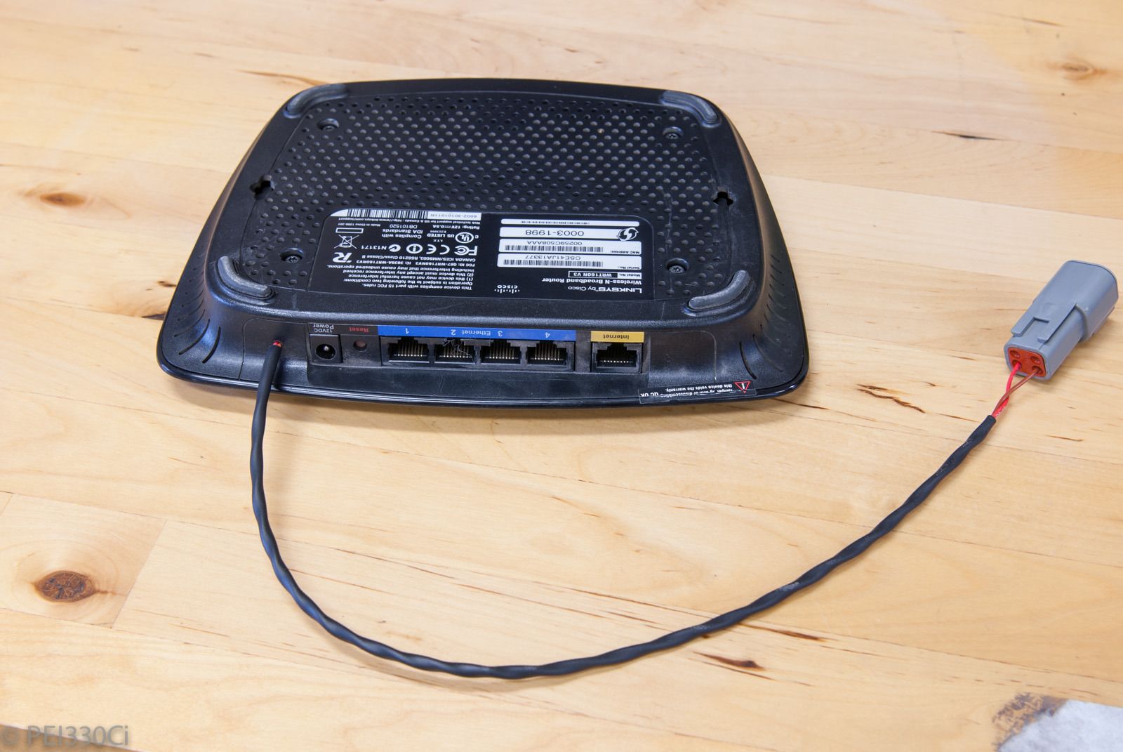
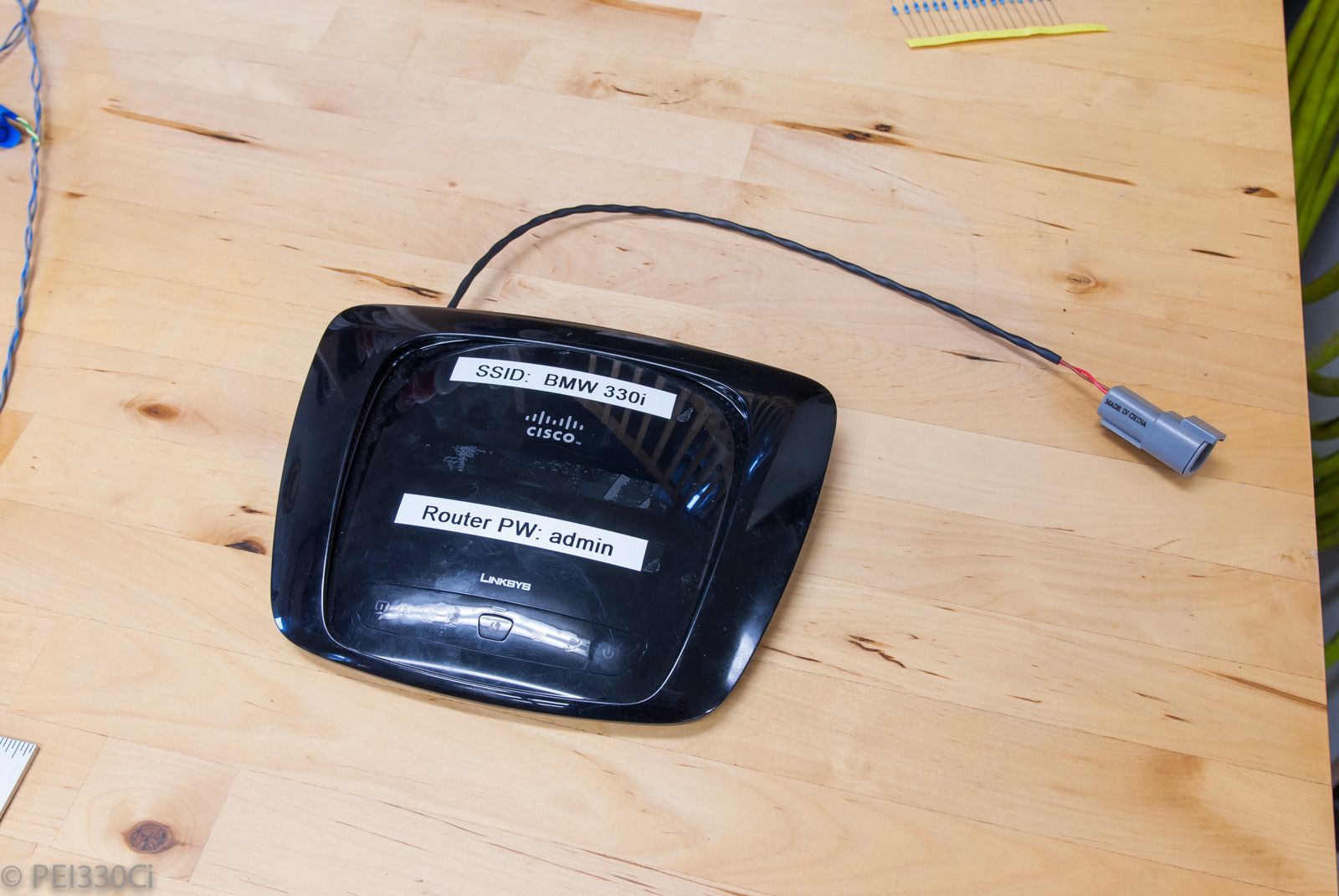
Motorsport Wifi:
The C125 dash, and M150 ECU communicate with laptops via Ethernet. Instead of having 2 Ethernet connections, I decided to use a router, and it wasn't that much of a jump to use a Wifi router. I'll be able to communicate with the car in the garage, from my bedroom in the house. :P
- - - Updated - - -
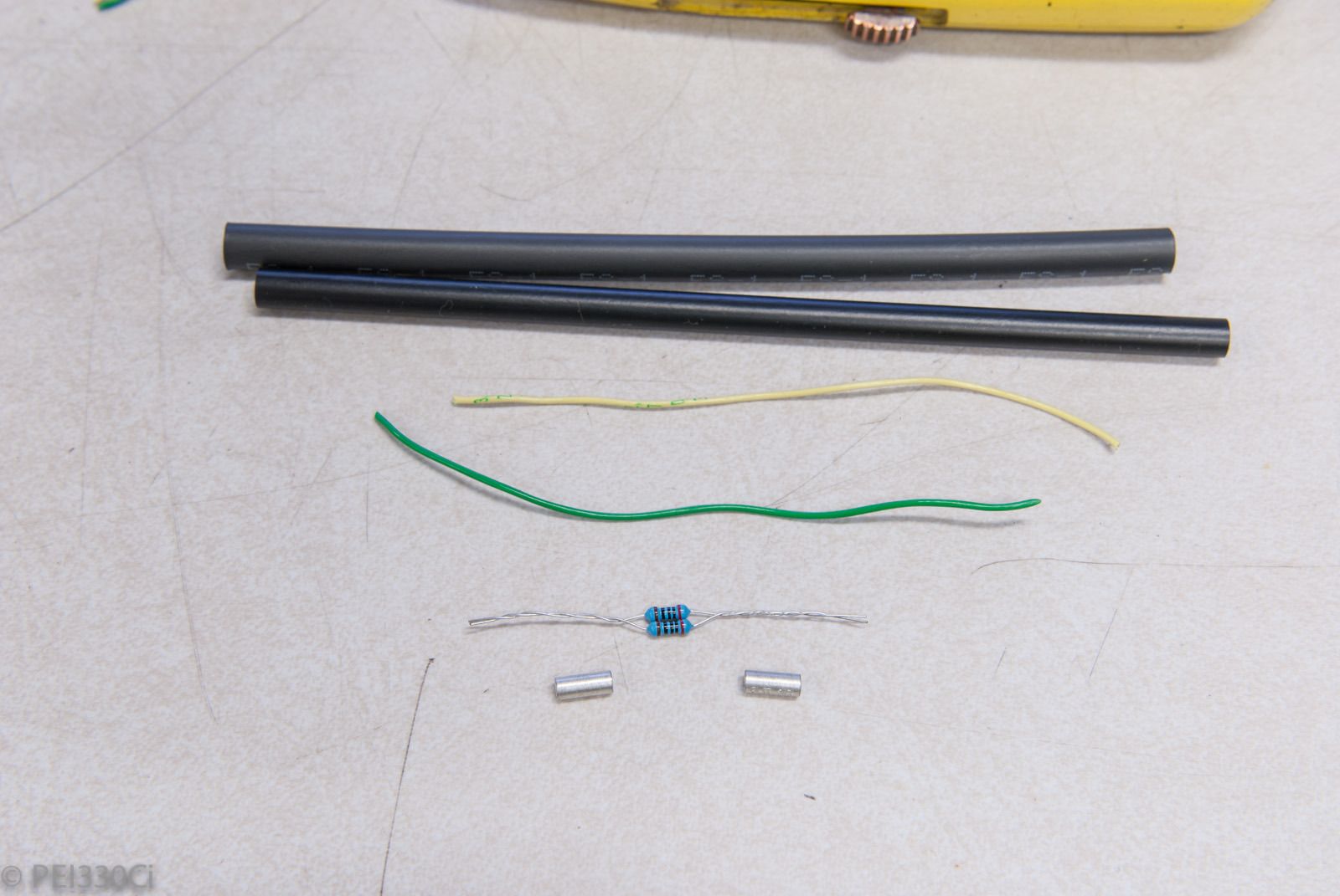
The CAN Bus requires a 100 ohm terminating resister on each end of the trunk. I have 3 functional CAN bus networks on this project, so I had to prepare a few to be wired into junctions. (Without soldering)
Heat shrink, 2 X 200 ohm resistors (Parallel), pigtails, and crimp barrels:
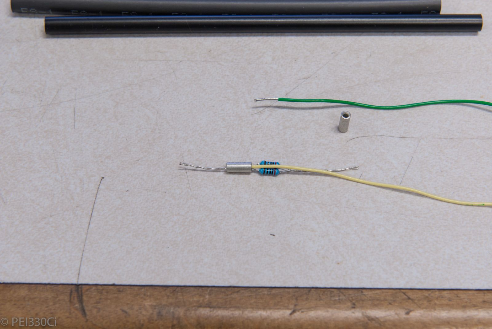
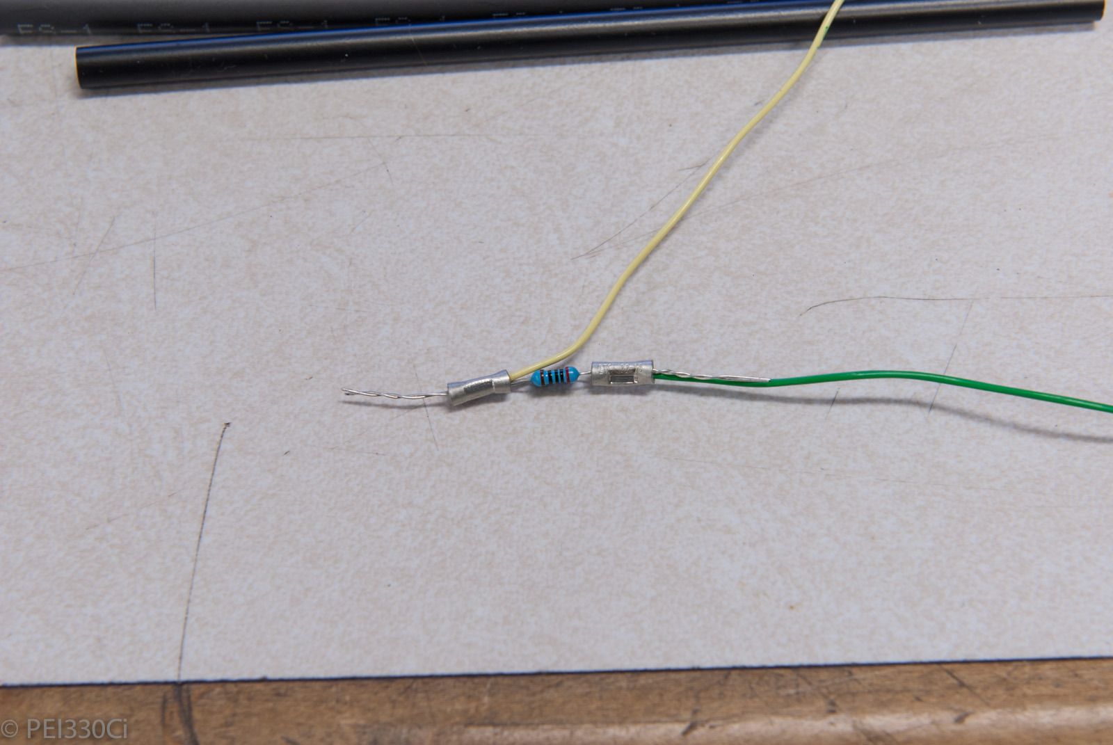
Assembly:
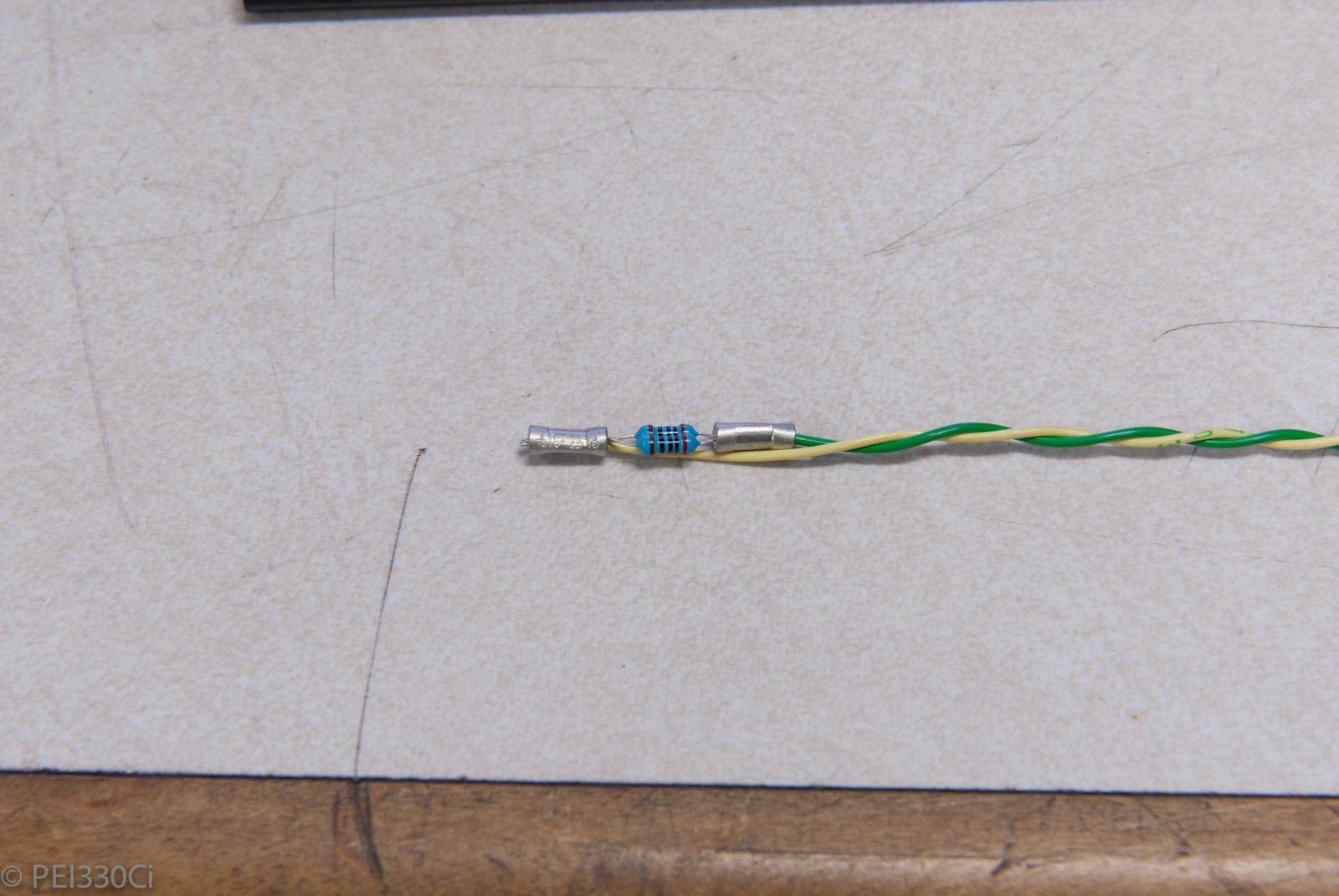
This specific one was then connected to a 7-way splice junction on the dash panel. (Lots of CAN devices in there)
Member
Wow, my hat goes off to you sir. You do really great work. Can I ask what you would say is the best way to go about to learn what you know about car ECU's, electronics....etc? I would like to learn more about this stuff so I can do my own wiring..etc not for a career, but just for my own projects.
M54B30 Inside
Find people that are doing what you want to do, and offer your time to help them. In most cases, you just have to show and start doing stuff. I spent hundreds of hours helping other people for free. That was the start. I read user manuals, downloaded software, and a few companies offer really good webinars for their products. (Motec is the best) I spent years just absorbing what people were doing, and how they were doing it. Lastly, I started just building stuff for the sake of building it.
I made, and continue to make a lot of mistakes. Probably 30% of my supplies get eaten up by mistakes, or trying stuff to learn. If you need 5 connectors, order 7. 1 will probably get destroyed during assembly, or you will use up the pins learning to crimp, or simply putting them on the wrong wire. 5 will be used, and 1 is good to have as a spare in case you change your wiring plan.
On the software side, I actually don't recommend getting into M1 Build unless you have a programming background, or already are tuning cars successfully. Probably the best online resource for tuning right now is High Performance Academy. I continue to purchase tutorials from them because they are extremely practical, and address questions that never get answers "online".
Lastly. Just keep asking questions. I don't mind handling things via PM, or if it's really drawn out and elaborate, via email.
Member
Thank you very much for a very informative reply and your helpful advise. Keep up the good work of making us drool over your quality work,LOL
M54B30 Inside
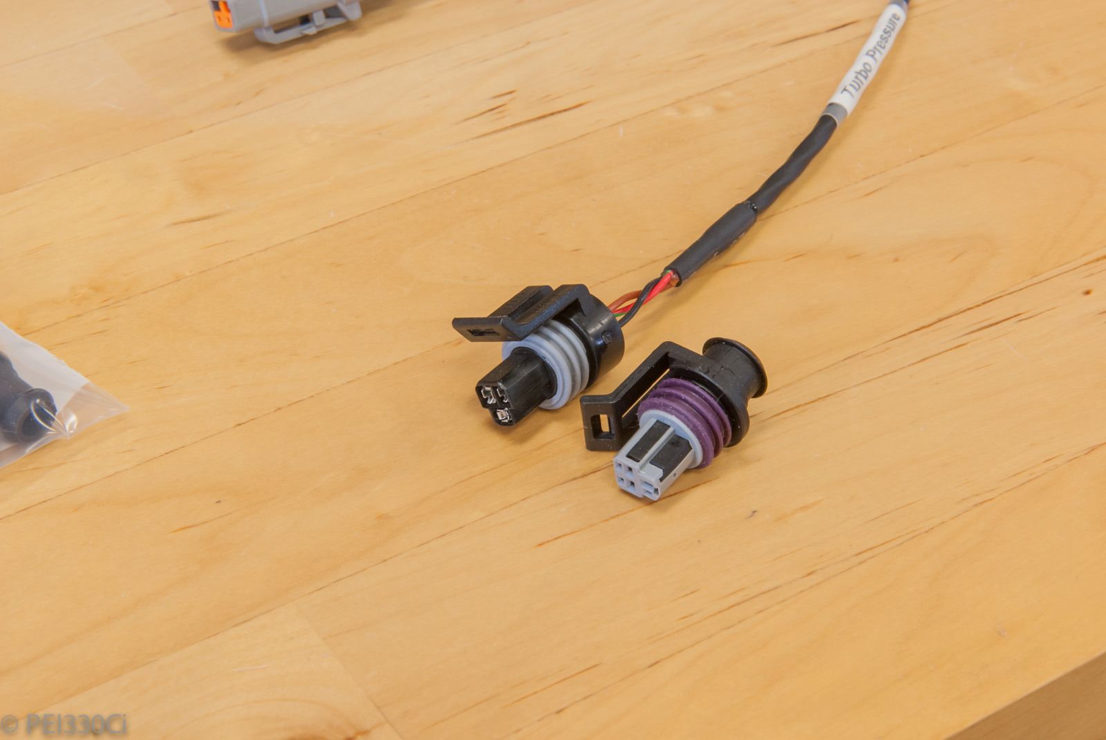
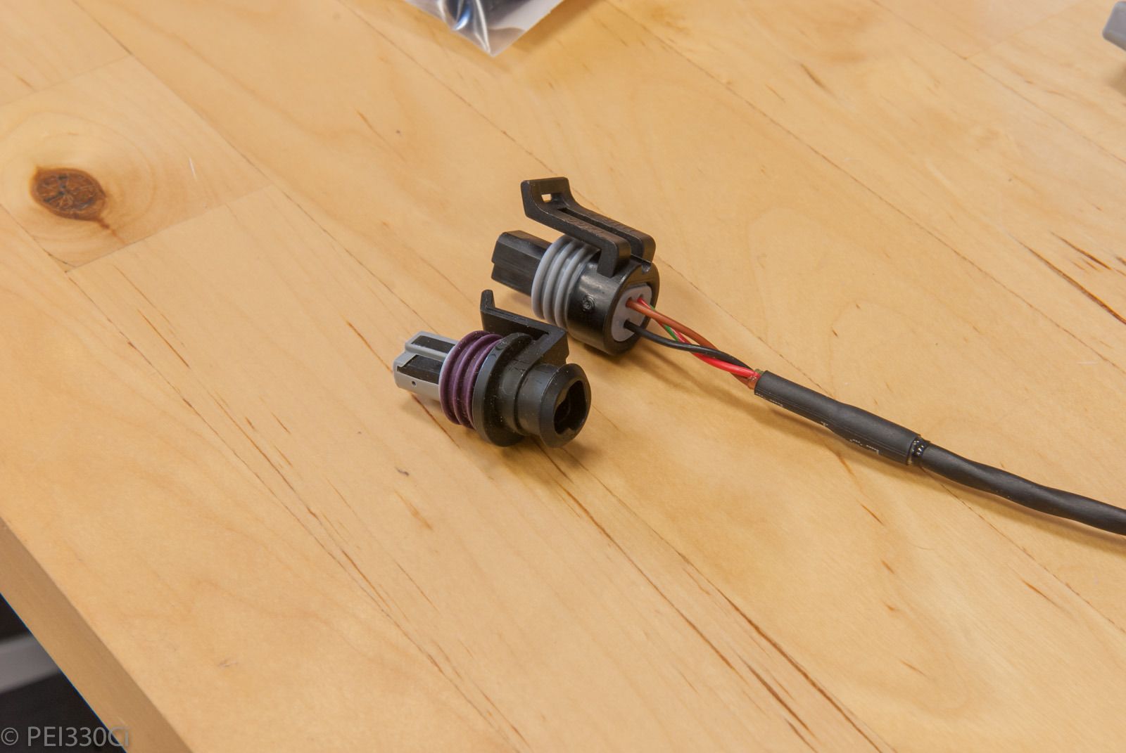
AEM supplies connectors with their pressure sensors that I don't like. There's no lip on the back for boots, and the sockets are crimped in front of the connector, then you pull the wire back to draw the sockets into the connector. (Wire is placed through the connector, then you attach the socket, and pull the socket back into the connector housing) I've sought out replacement connectors for every AEM pressure sensor on the car.
The connector with the purple seal-ring will replace the connectors from AEM with the grey seal-ring:
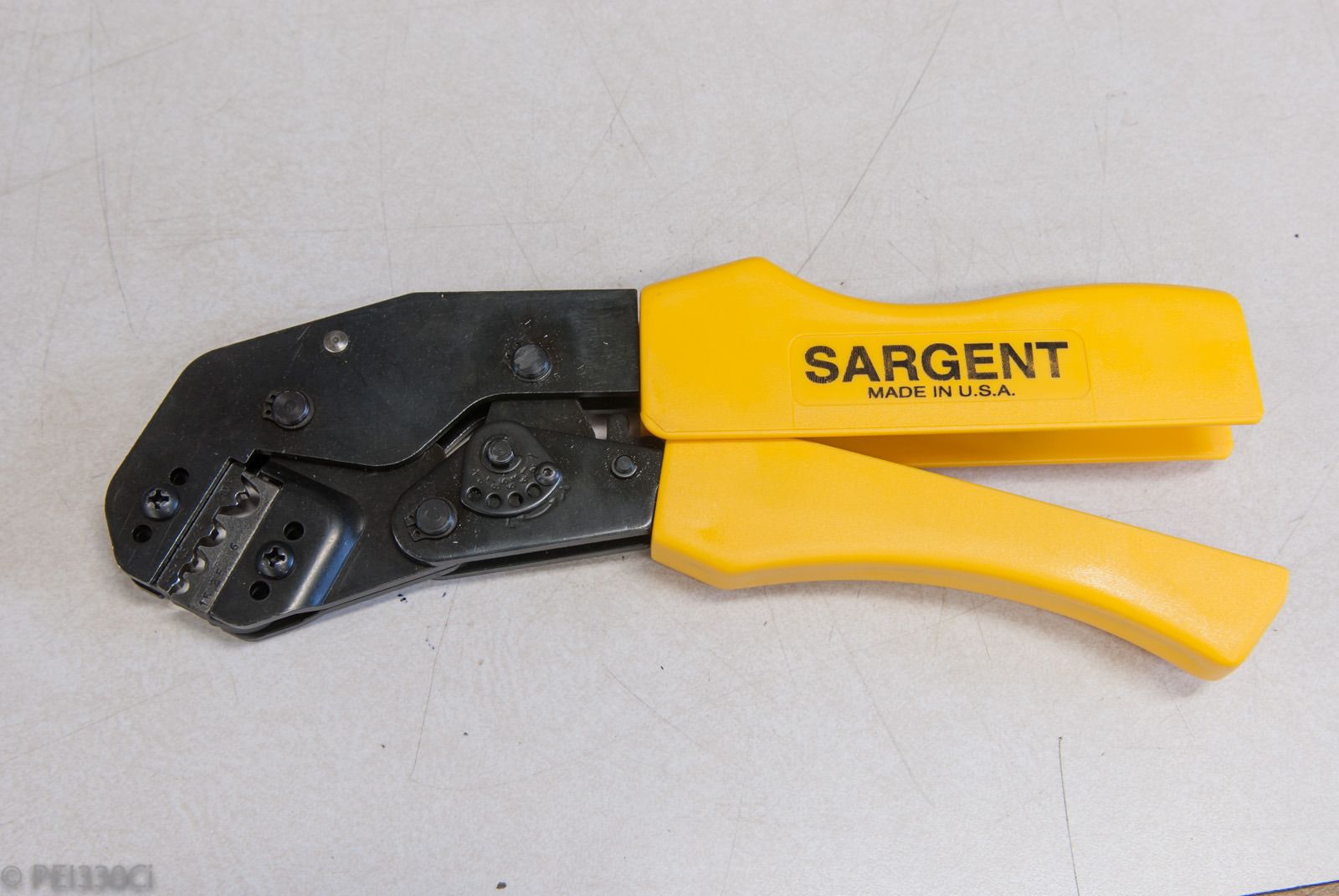
I've received a few inquiries about the crimper I'm using for 8, 10, and 12 awg splice barrels. Here it is:
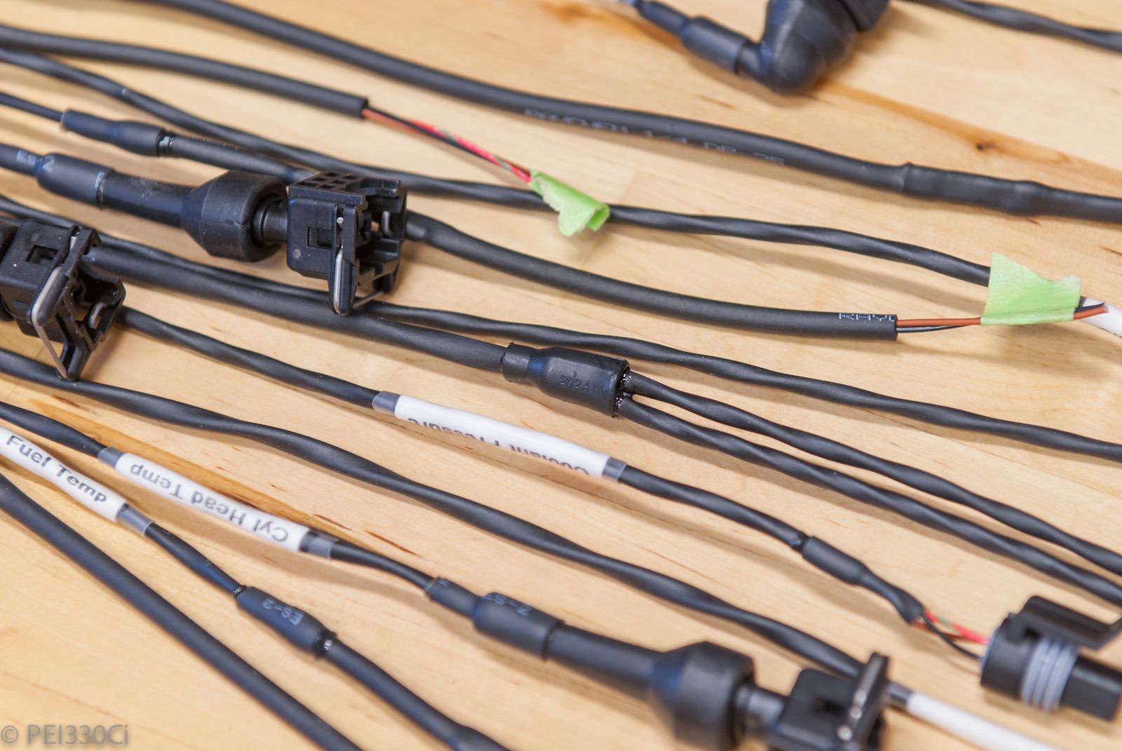
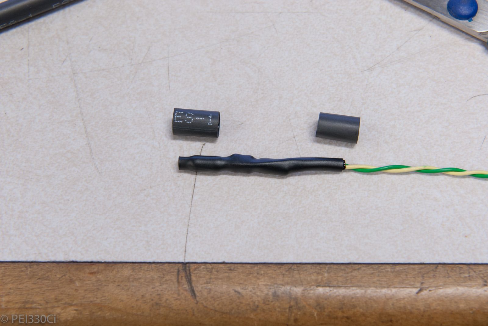
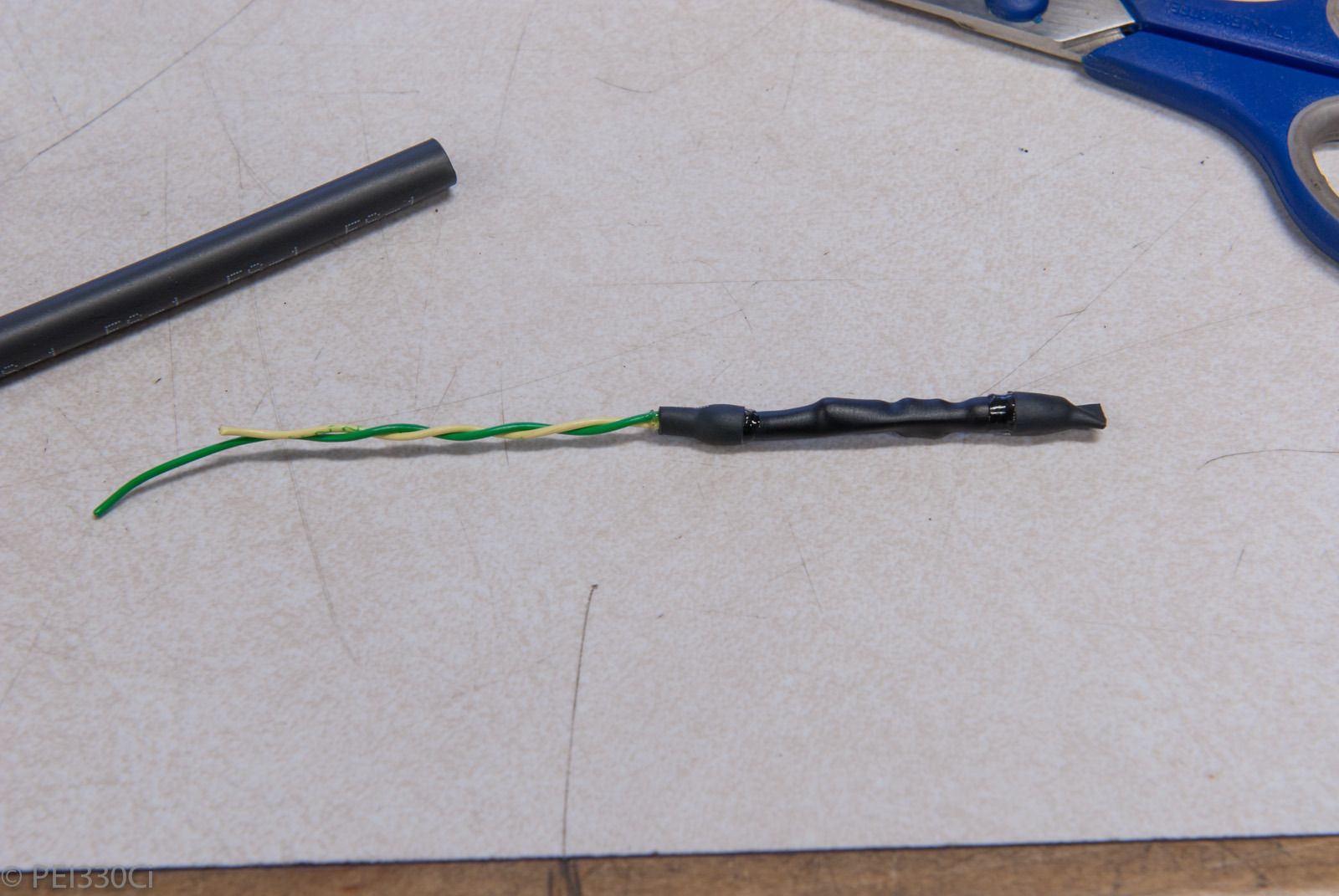
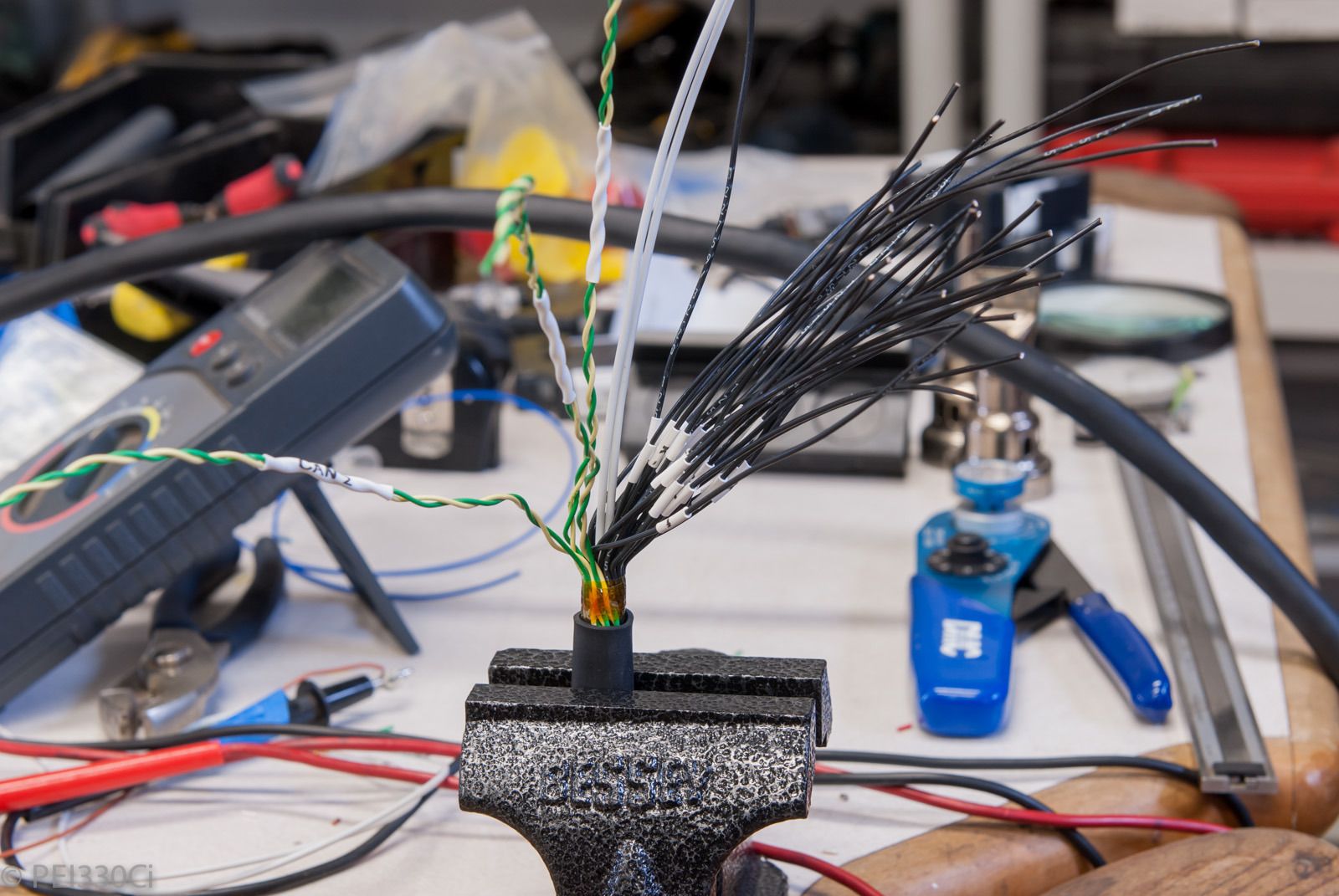
And for those that wonder how I keep track of wires at the end of concentric twists:
Yup....I label them all with 6mm Demo heat shrink. This makes it easier to assemble, troubleshoot, and/or re-assign later as required.
A problem I ran into when re-installing bulk-head connectors was reaching the fasteners on both sides. If the connector goes through the firewall, you need 2 people to mount it. So I broke out the epoxy to hold the stainless steel fasteners on one side:
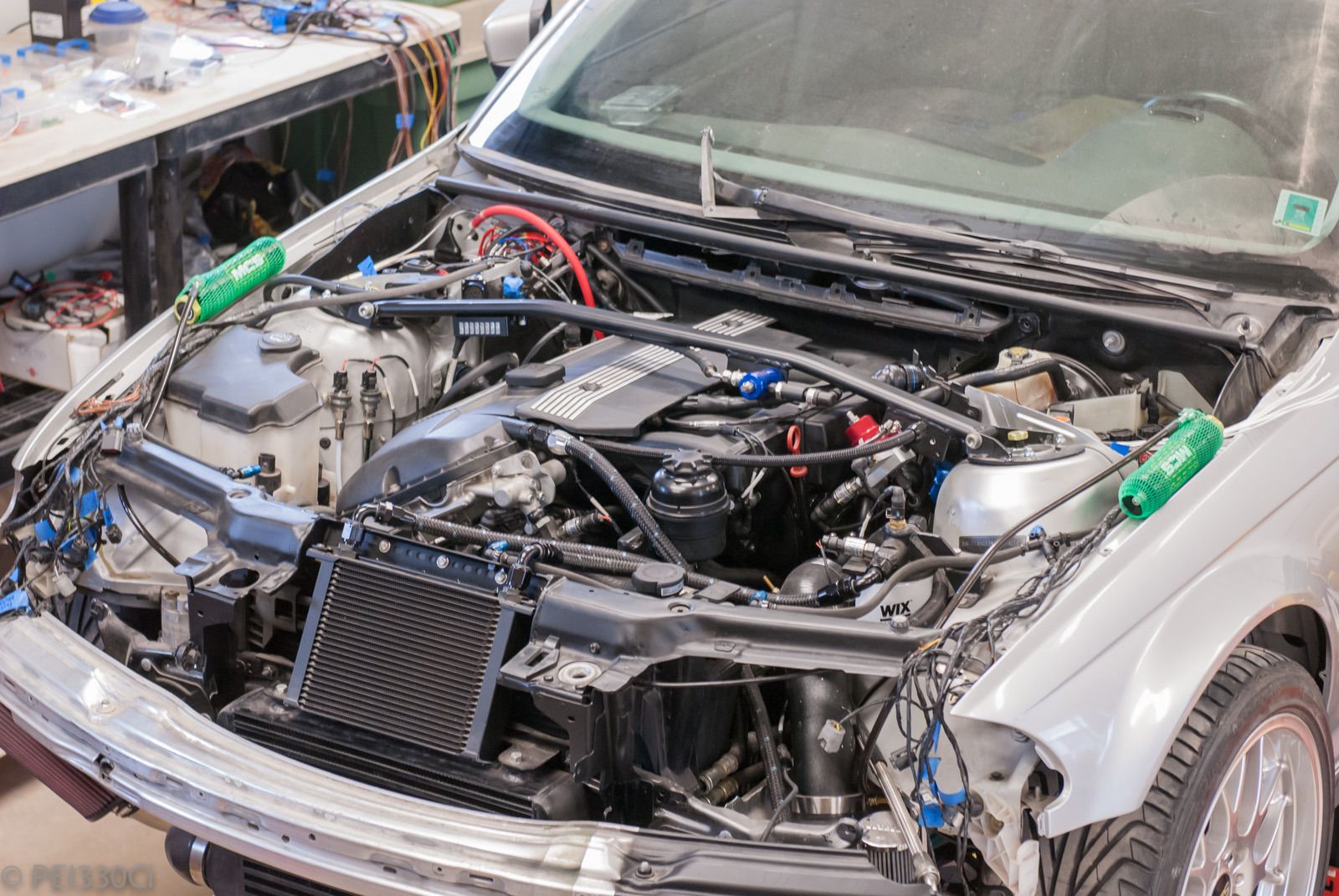
And for those wondering how far along re-assembly of the car is:
Yup...those are engine covers mounted.
Aside from wiring and software, the mechanical side of the car is 100% done.
Member
And your wife doesn't have an issue with this?
BTW, very nice work going on in this thread...
WOT
M54B30 Inside
I would get kicked out to the garage...
Member
WOW. I rarely read any turbo builds, mostly just come in to look at the fab work. I don't think I can honestly say I have sat down and read every page of it...until this. I was expecting a turbo kit slapped on and what I have just seen and read is by far one of the most intricate and amazing builds on BFc, one in which my mind has actually been blown at 10 times haha. I tip my hat to you sir, and I will actually be following this build closely. Keep it up!
Member
thats crazy! I was thinking the same thing. I have a crap load of pressure sensors but they were all resistance style.....I found stainless pressure sensors bran new on ebay for 20bucks a piece. theyy looked identical to the aem. pinout was the same...accuracy...everything. got them in and figured for 60 bucks why not. until I got to the hood for the connector. I was thinking.."I'll bet the AEM ones are done better". oh well 60 bucks. got one going on fuel pressure and oil pressure. I replaced the cables though.
so on that note. I have the aem liquid temp sensors. crappy connectors as well. the ferrules anyways like to come apart at the crimp. do you know what ferrule or connector that is? 2 wire D shaped thing?
Member
AEM sensors are just stickered up http://www.kavlico.com/ units. I believe they are the P255 series but its been a while. If you contact Kavlico directly and buy a few you save a ton of money over AEM. I have one in manifold, fuel, oil pressure (in two places), water pressure, and nitrous pressure. I want to throw one in the brake line so I can make more sense of log files also. They work very well.
M54B30 Inside
Thank you, much appreciated!
I'm not clear on what you're asking. The contact sockets are like a butterfly crimp; 1 blade on each side of the wire, and the crimper folds them into each other in a double-hump.
The vendor I'm using for wiring supplies is doing his own pressure sensors now; you'll see them on the water injection system. (1 for pre-turbo injection, and 1 for manifold injection) Have you seen the new ones from Motec with an ASL connector?
Member
That's awesome (and expensive!)
I think if you order from Kavlico directly you get different connector options. At least you used to be able to.
M54B30 Inside
I should add that a lot of my choices now depend on what the vendors I use recommend. They continue to answer my "beginner" questions, so I continue to endorse their recommendations.
Member
Yeah, you'll find that Kavlico is the mfgr for almost all pressure transducers - they make almost every pressure sensor I saw in aerospace. Then the automotive guys come around, get a 1,000 unit price break, slap their sticker on it, and raise the price $100.
Member
I always thought jems was the big boy in pressure sensors but I never researched it, just picked it up from other people I relied on for that part of the equation. good info.
from what I understand you have 3 categories.
low cost
high accuracy
and long lasting
Bosch made a proprietary dual eddy current transducer that was as accurate as strain gauge style but could be spiked by 2 or 3 fold of nominal and it would not skew the results or damage the sensor.
I believe the piezo electric is the one that is readily available and has reasonable accuracy and can take big pressure spikes. like backfire or overboost. but like I said I never researched just took the fluid power guys word for it. does that jive with what you guys know?
Member
Alls I know is, I have the kavlico/aem 5 bar map sensor and the resolution is fantastic. Better than the 2 bar GM I used to use yet 3 additional bars of metering in the same volt window.
Member
and probably didnt pay a big premium to get something a little better.
 Posting Permissions


 Reply With Quote
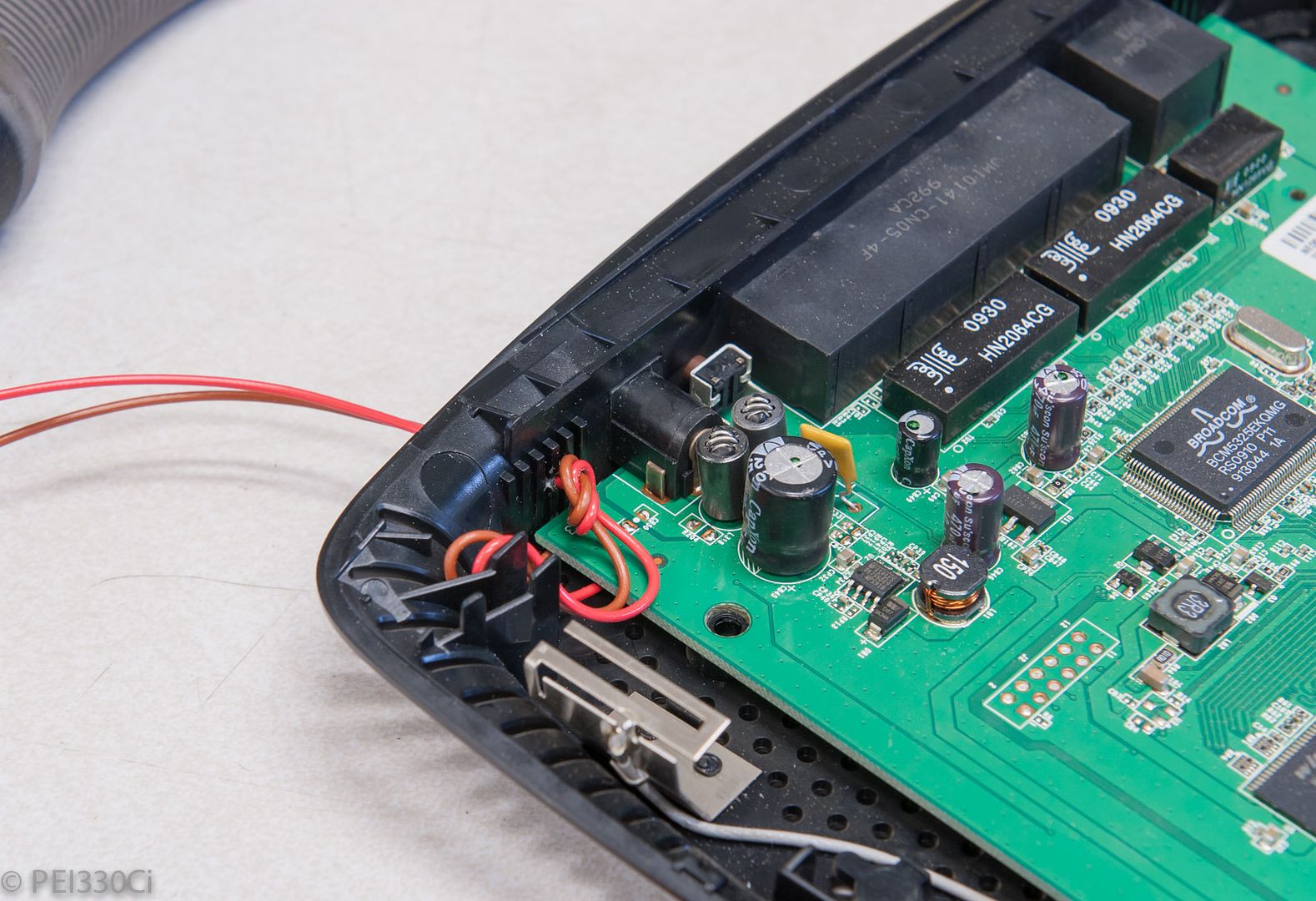


Bookmarks