
 Facebook.com/LUXFAB
Member
Facebook.com/LUXFAB
Member
Agreed, I'll shut up. In the end that's all I was really saying, that we all fine tune our projects to satisfy our need for kicks in our own way. The same way Boris, and many other racers I know, can't possibly understand a rational explanation for not driving a racecar for years, I could never do wiring on the level Adam does. Speaking of threads of this caliber, it's time you bumped yours manOriginally Posted by Colby Colbs


Member
This is getting good!! I need more pop corn!
M54B30 Inside
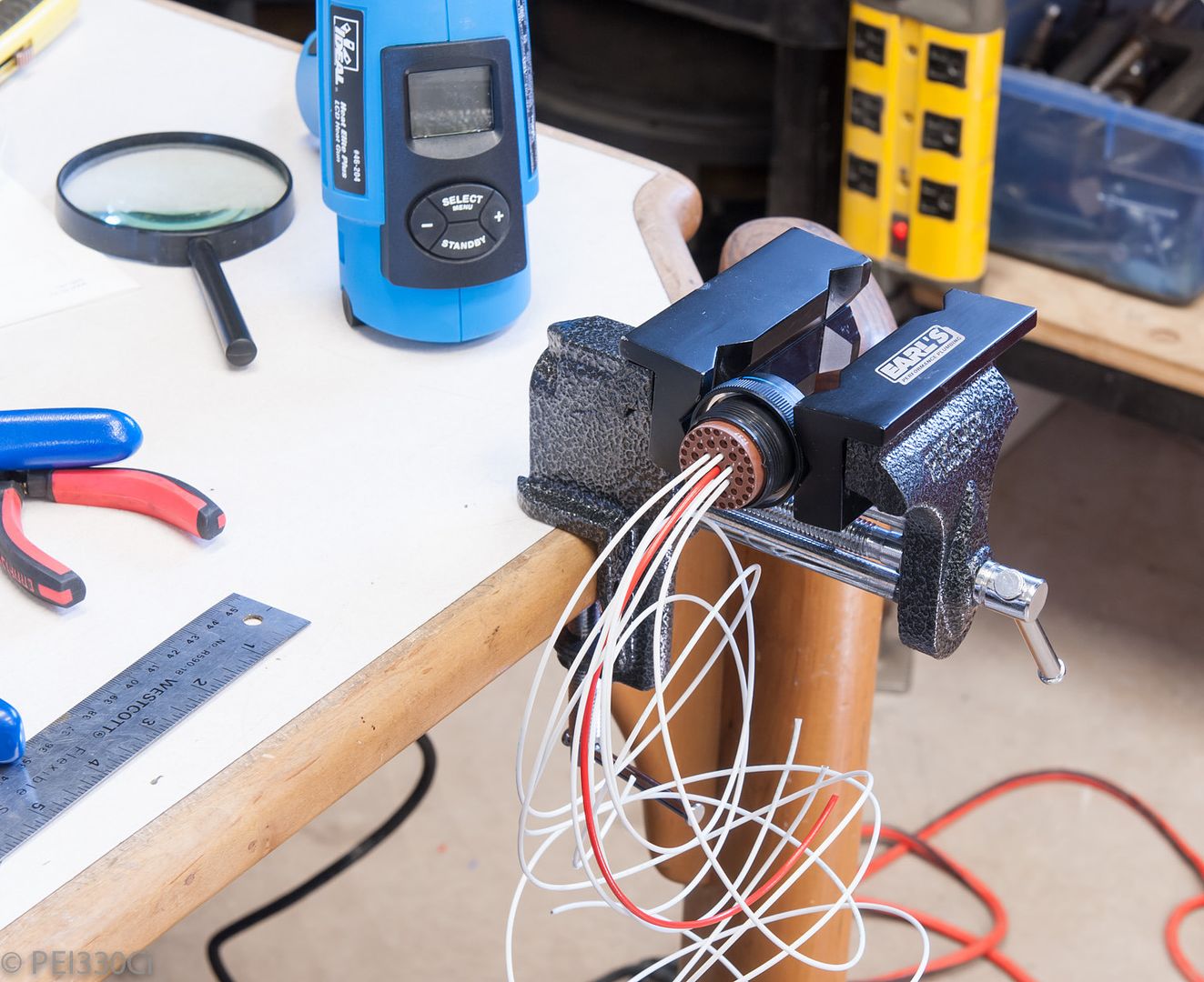
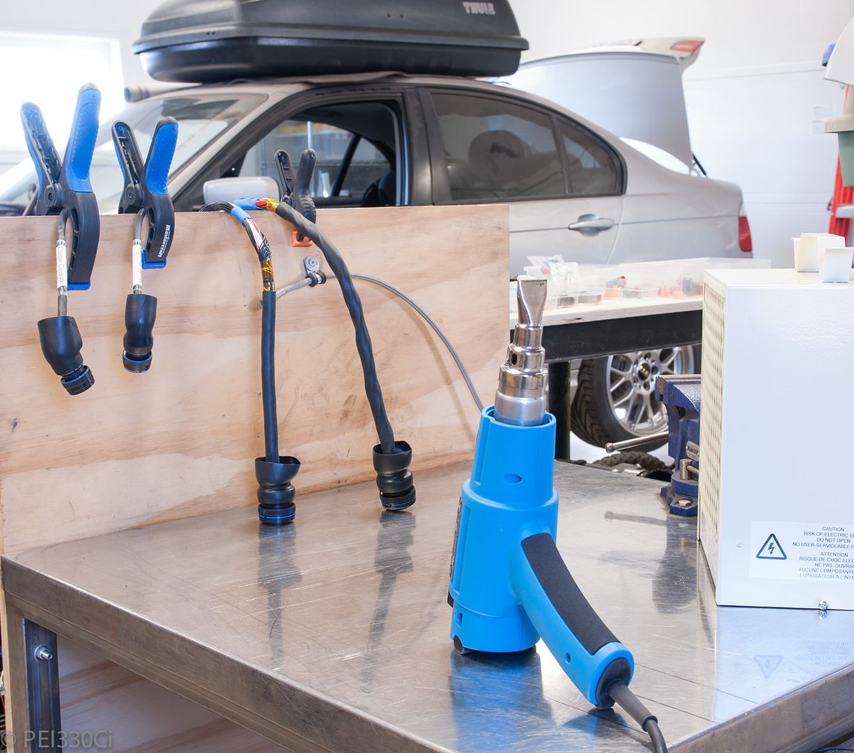
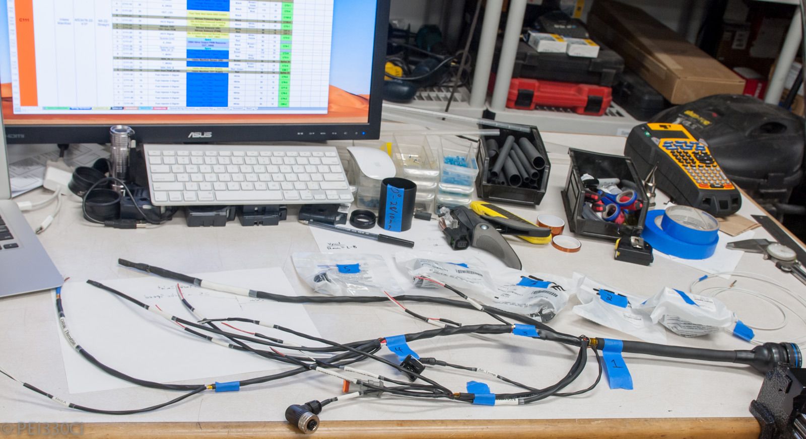
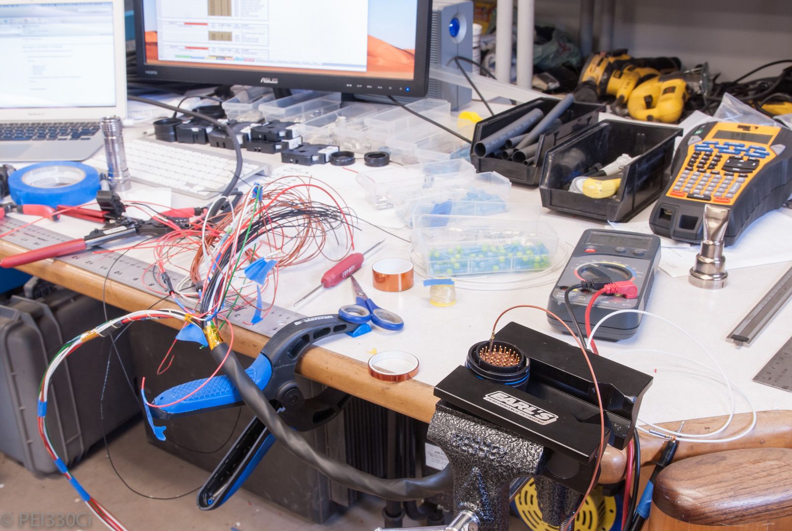
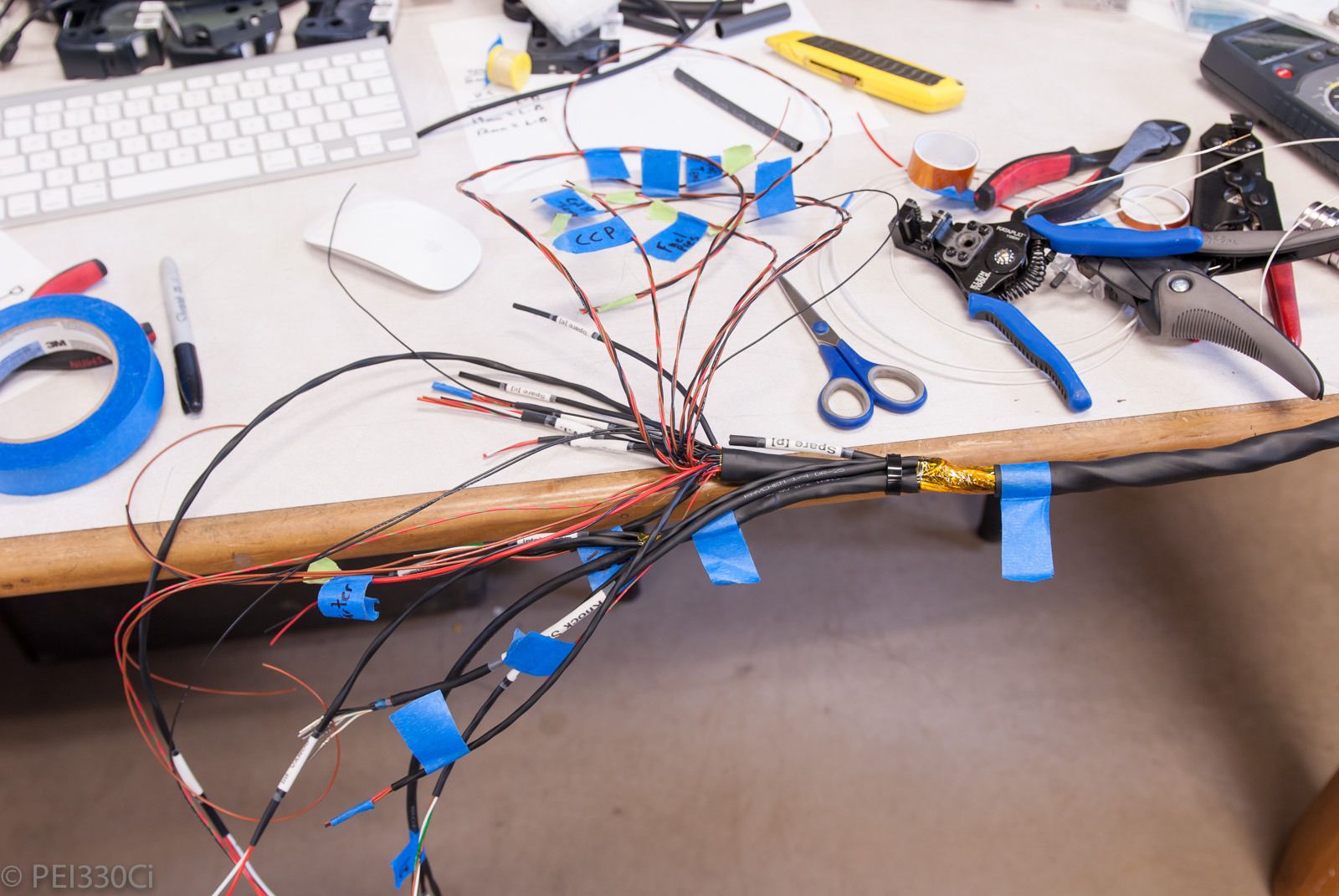
Received some new tools for the harness work:
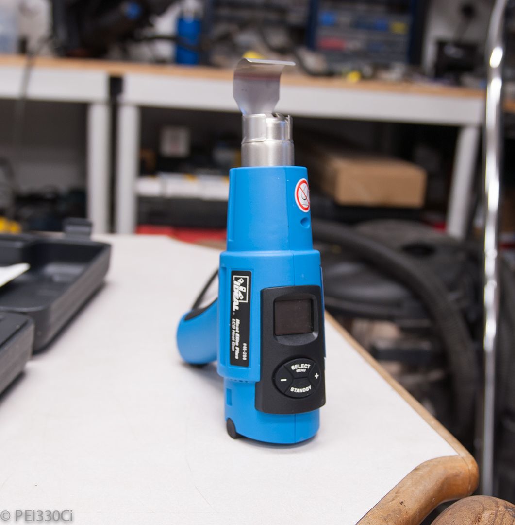
Programable heat gun:
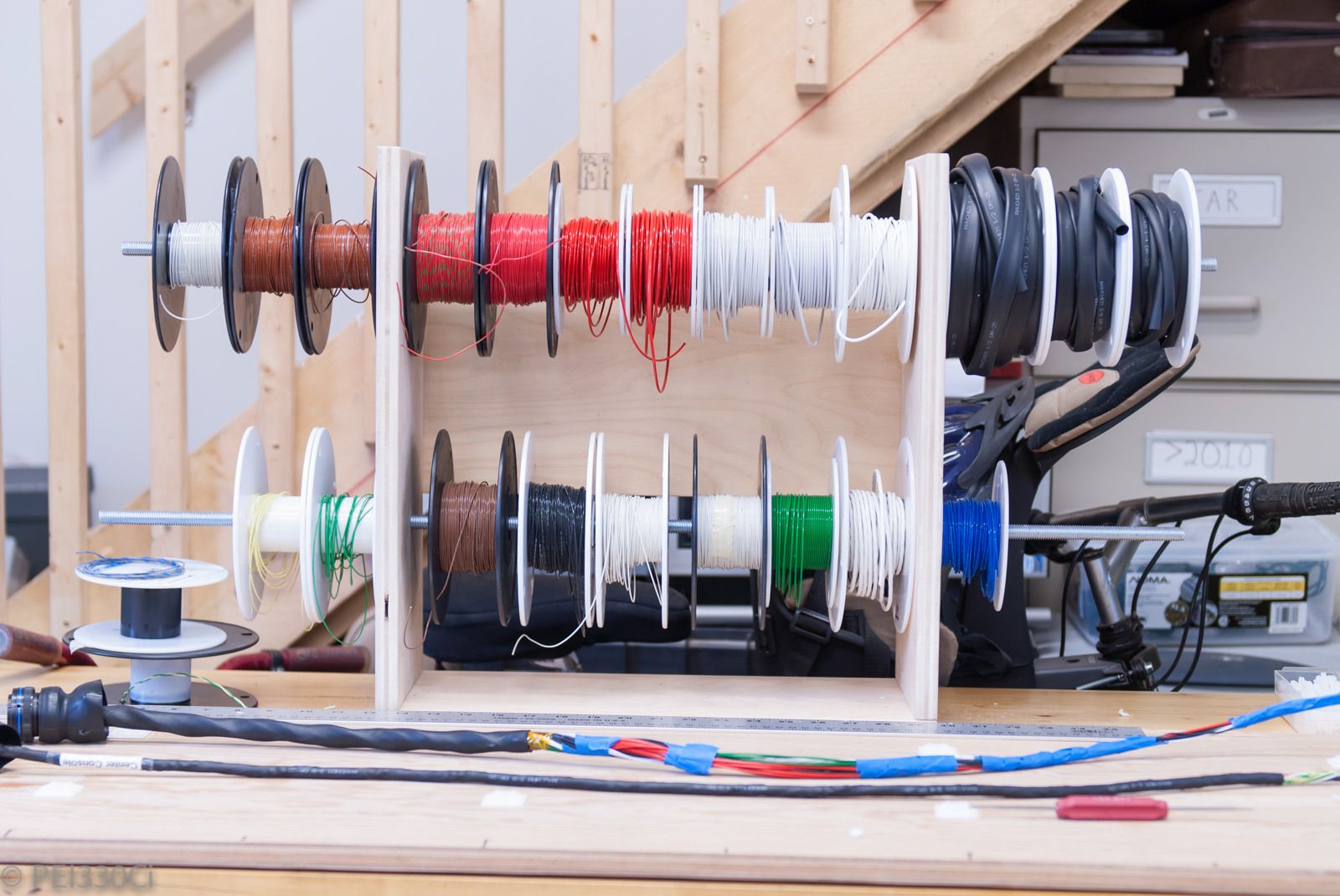
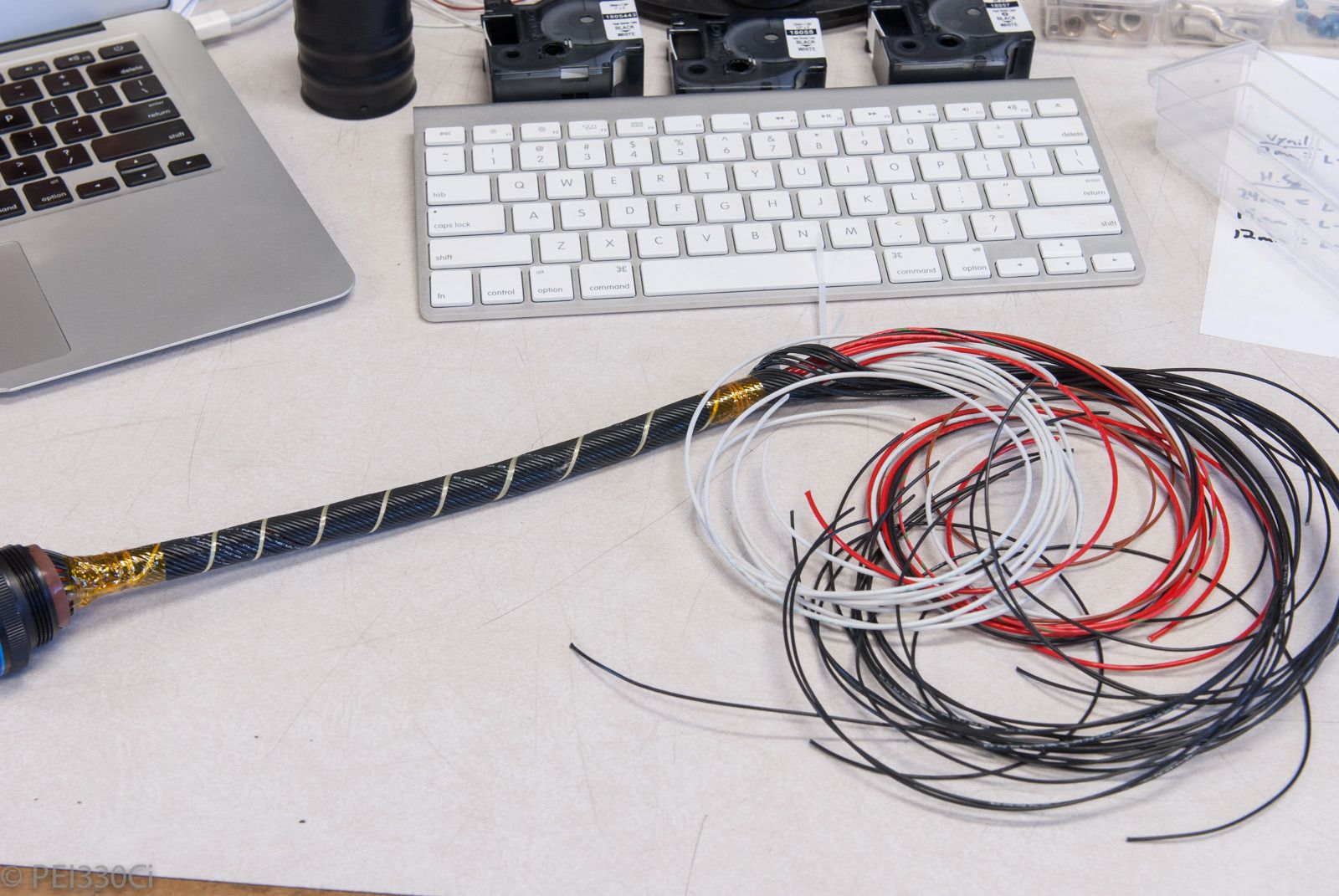
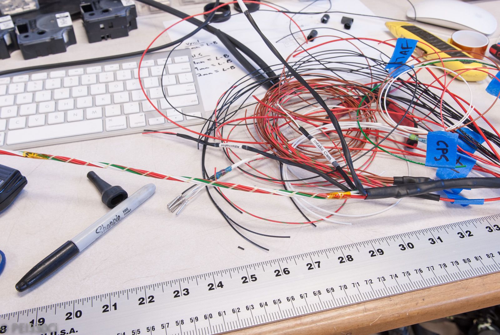
More wire stock, including some new spools of DR-25:
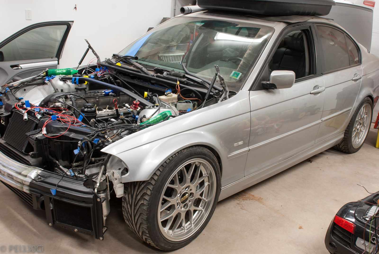
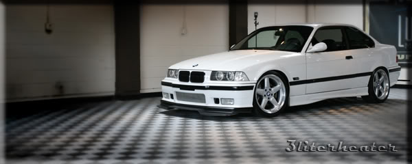
The MCS coil-overs have about 70mm of height adjustment. Because I want to run a "street" setup, (400b/in - 6" tall springs in the front) I set the adjusters 40mm from the bottom. This is what that looks like:
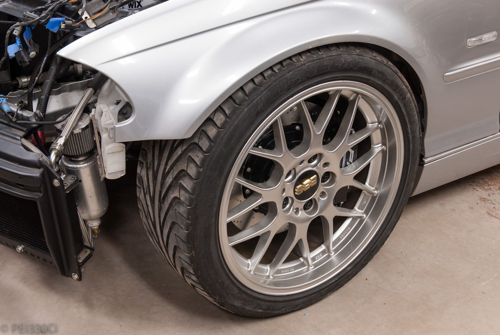
The wheels on the front are 18 X 8.5" ET38, with 17mm of spacer behind them. Tires are 235/40/18 Michelin Pilot Sport, but I'm thinking of changing to a newer set of MPSS 225/40/18.
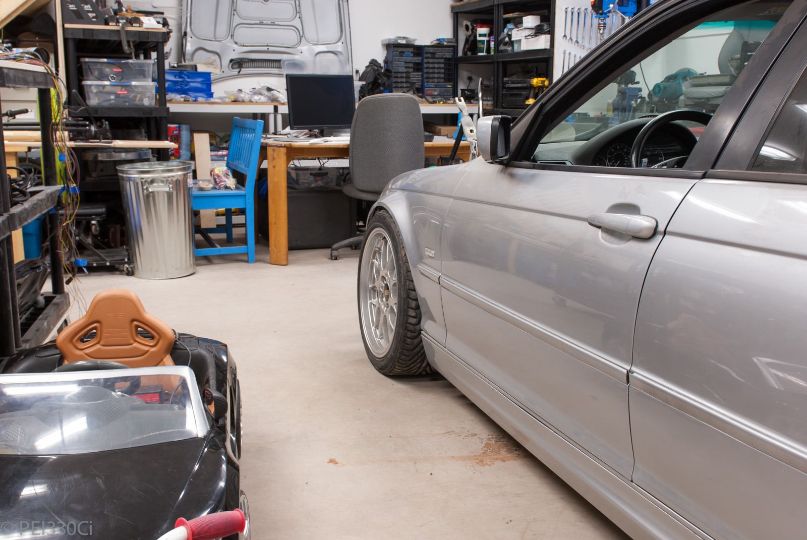
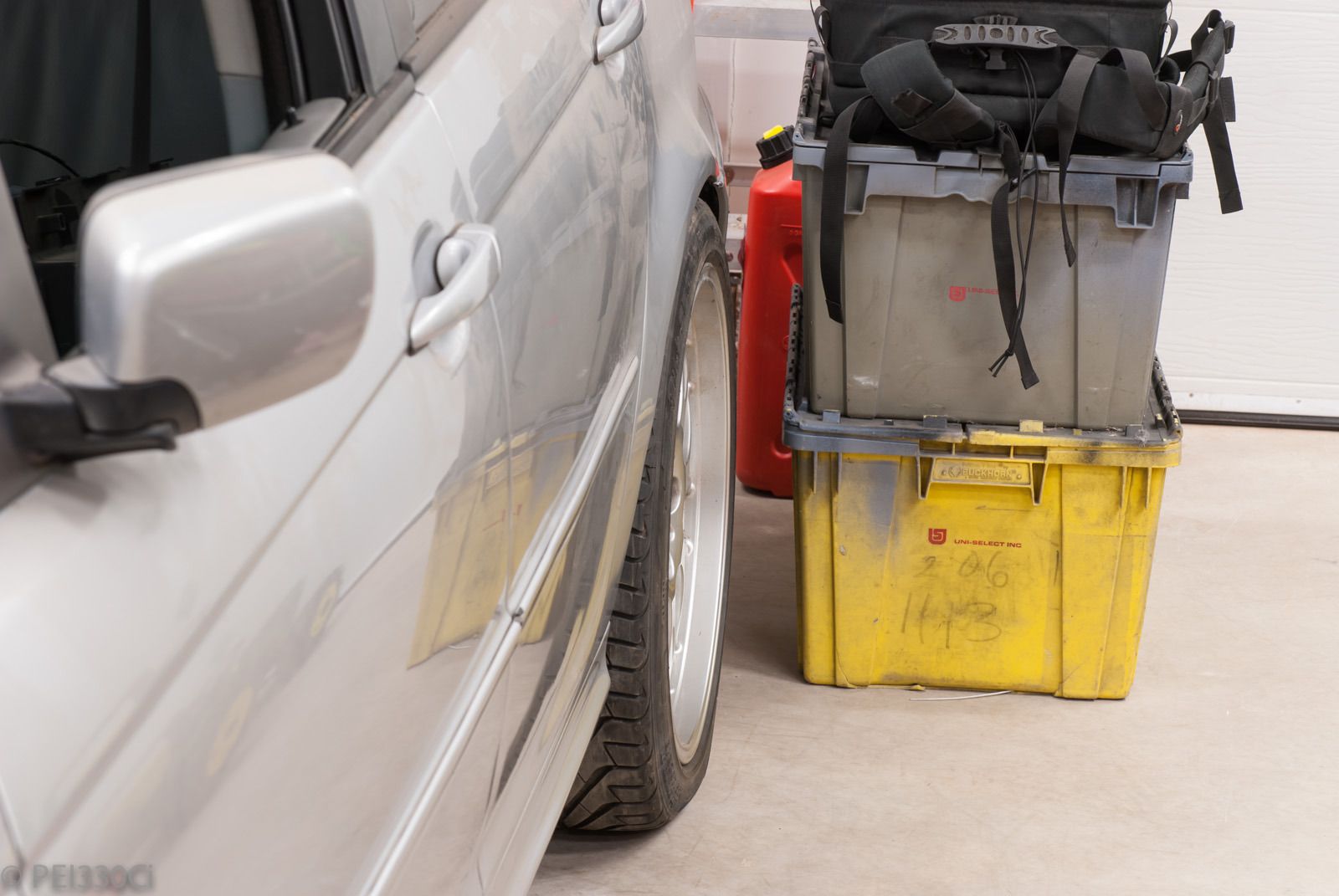
Rear wheels are 18 X 8.5" ET38, with a 10mm spacer behind them, and 235/40/18 Michelin Pilot Sport tires:
Over-all, the car sits a little too low, so I'm going to raise the adjusters another 10mm and see how it looks. Obviously, once I have the car assembled, I'll be setting up the final suspension heights by corner balancing. But to start with, I need to set a right height that's comfortable for the horrible roads we have up here.
- - - Updated - - -
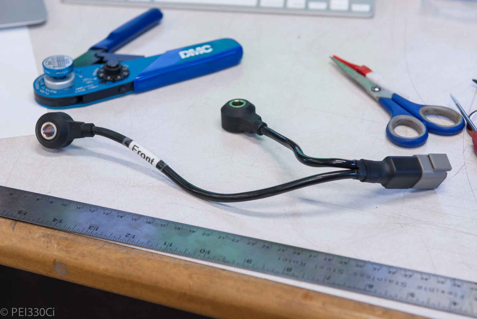
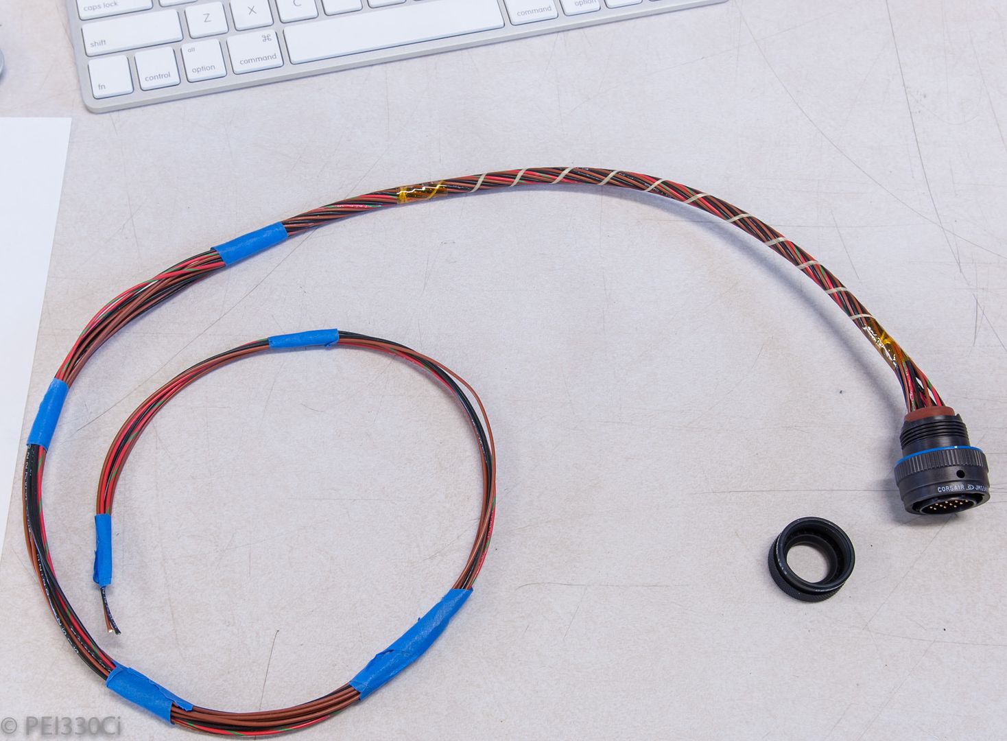
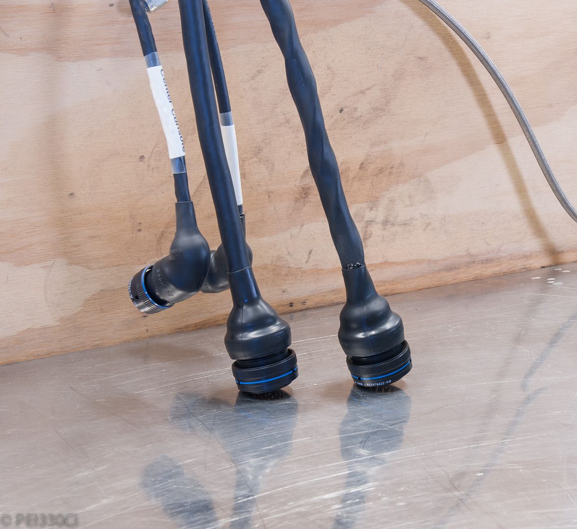
Re-terminated the OEM knock sensors:
Terminating the shielding on the knock sensor wiring:
*Note: I added a spare drain wire at the last minute above, that's one wire is outside of the glue lined heat shrink which acts as a strain relief to the bundle.
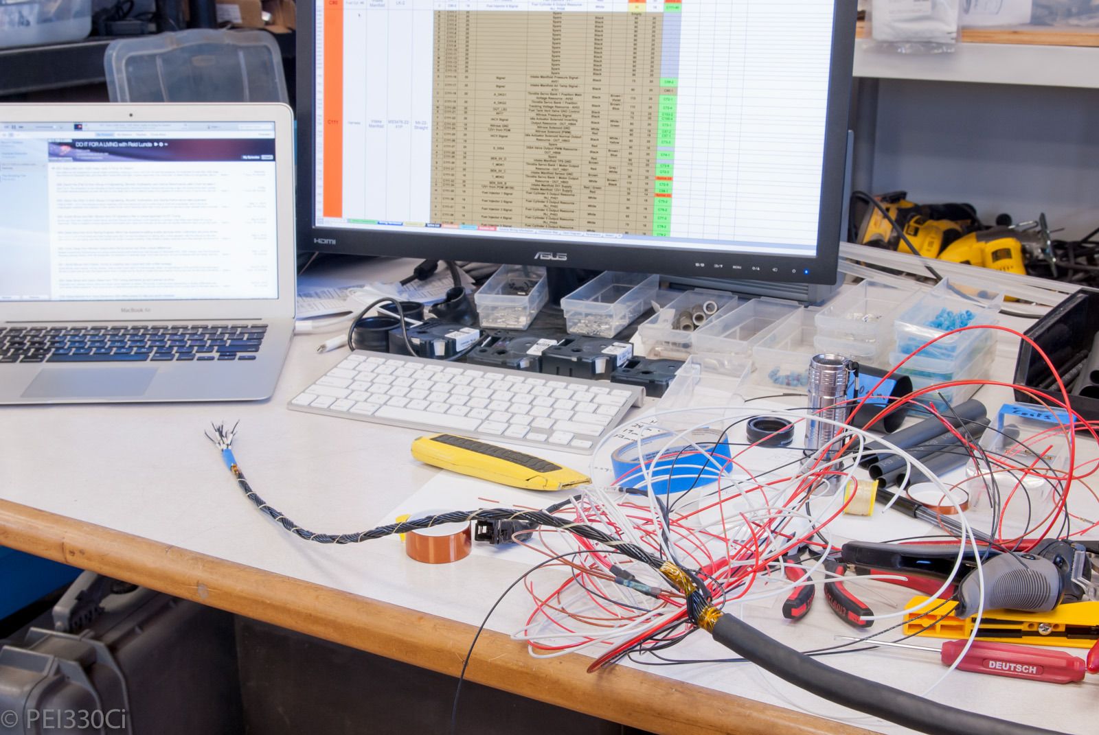
DME Bin getting sorted:
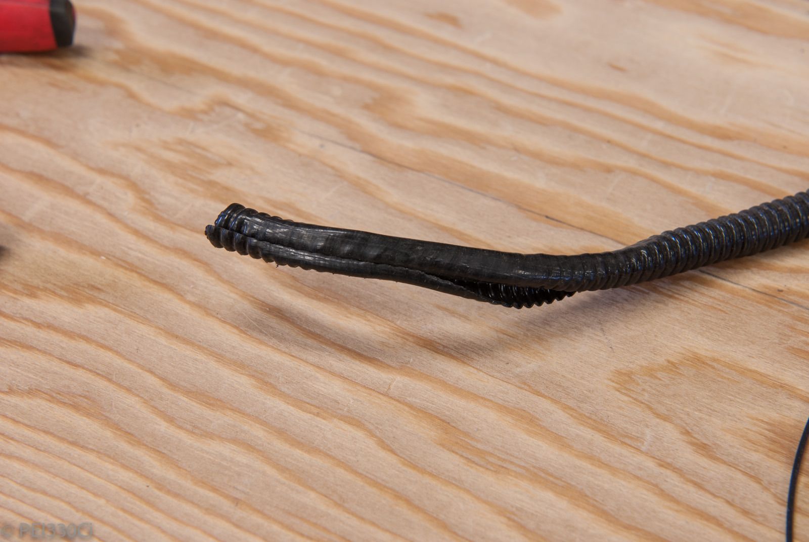
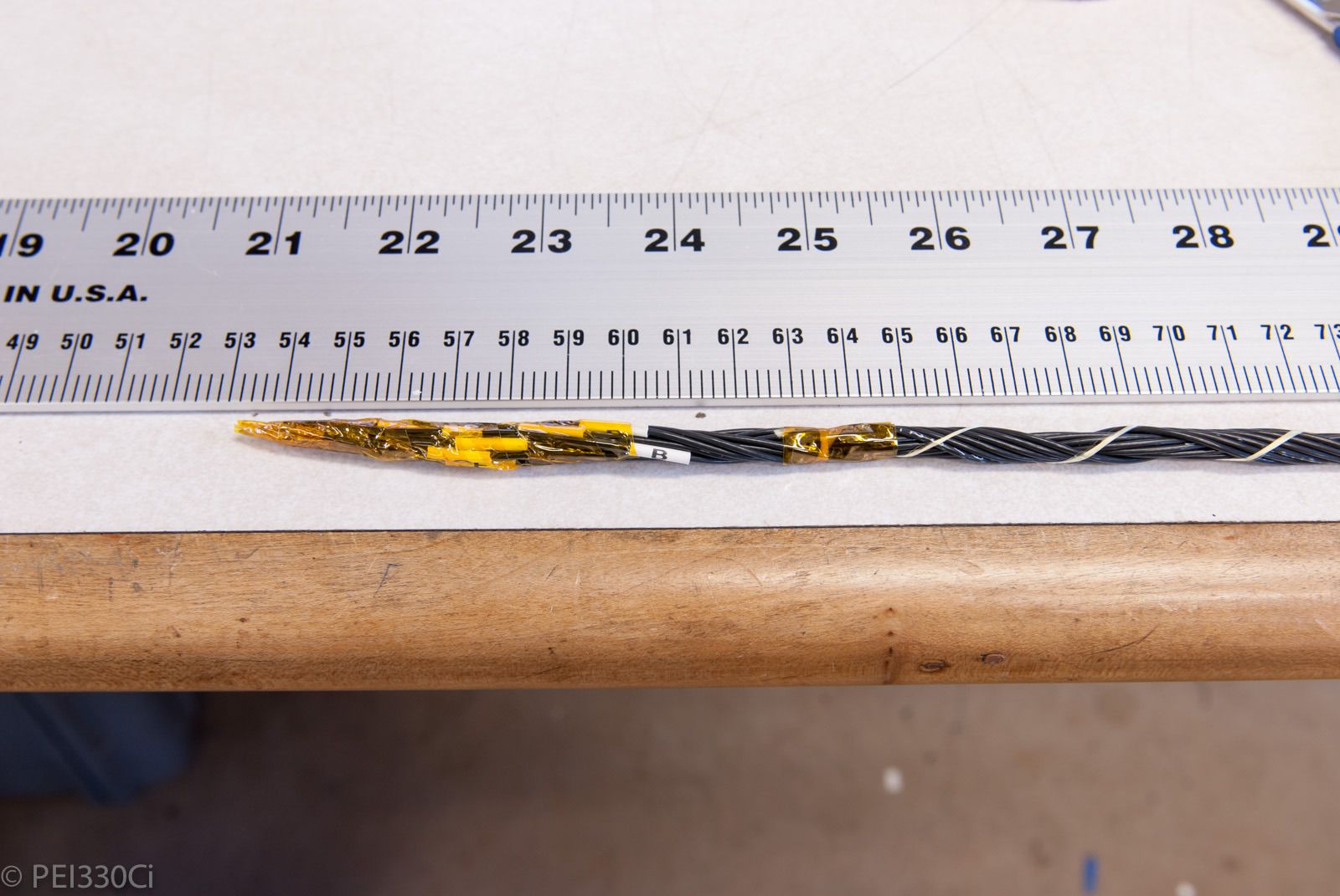
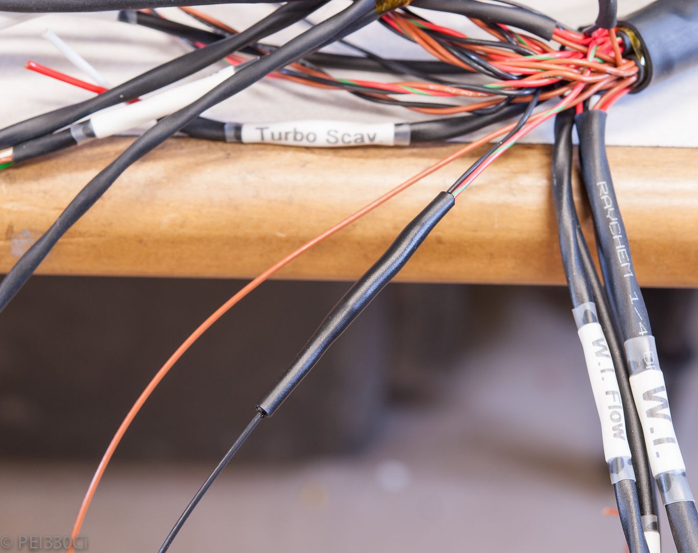
Plastic Sheathing I had on the turbo speed sensor wire melted:
I've now re-terminated the speed sensor to feed directly into the Motec M150, re-routed the wiring, and used DR-25 to protect it.
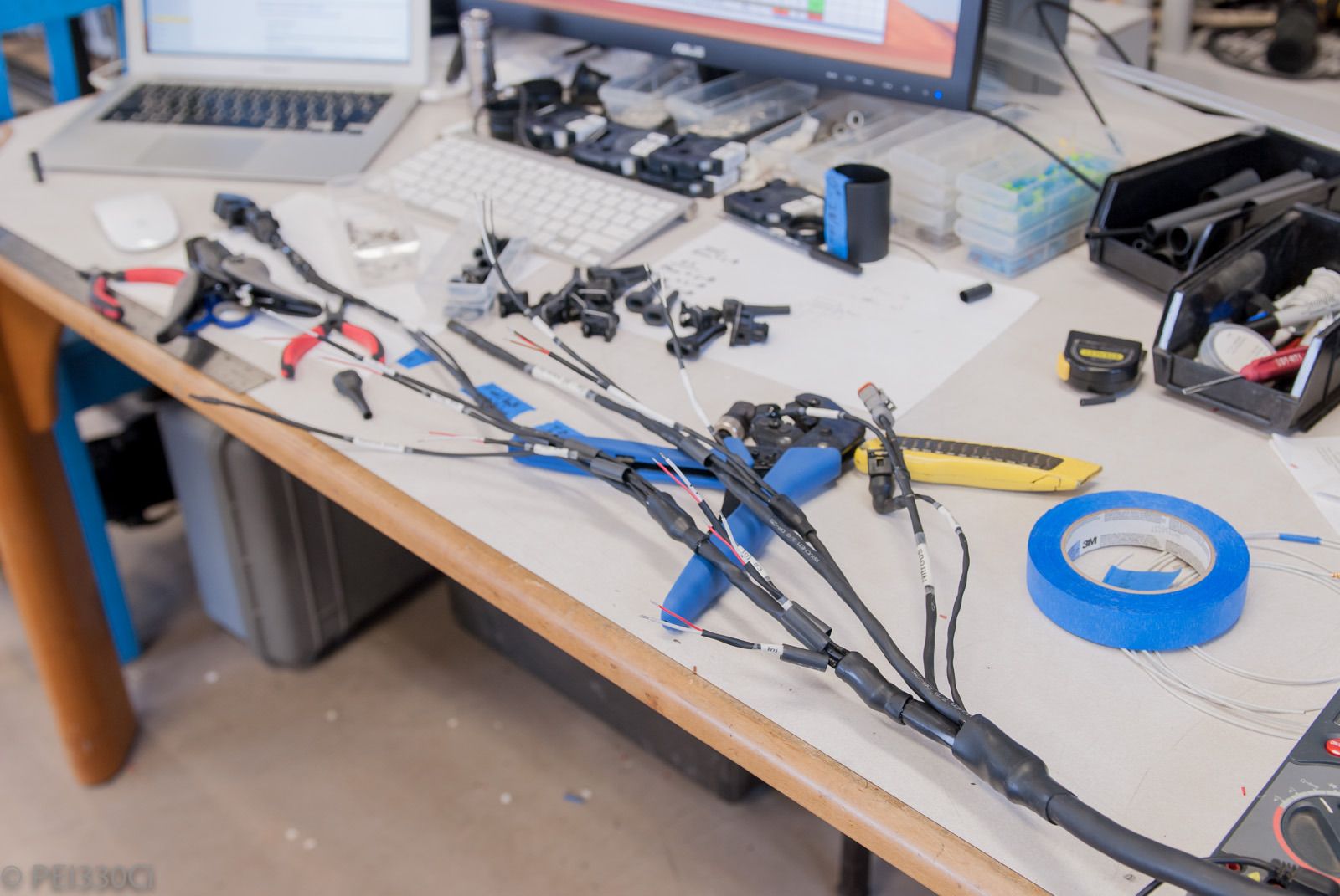
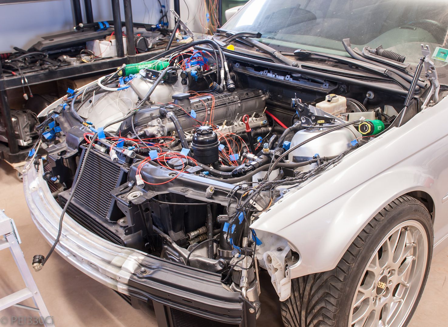
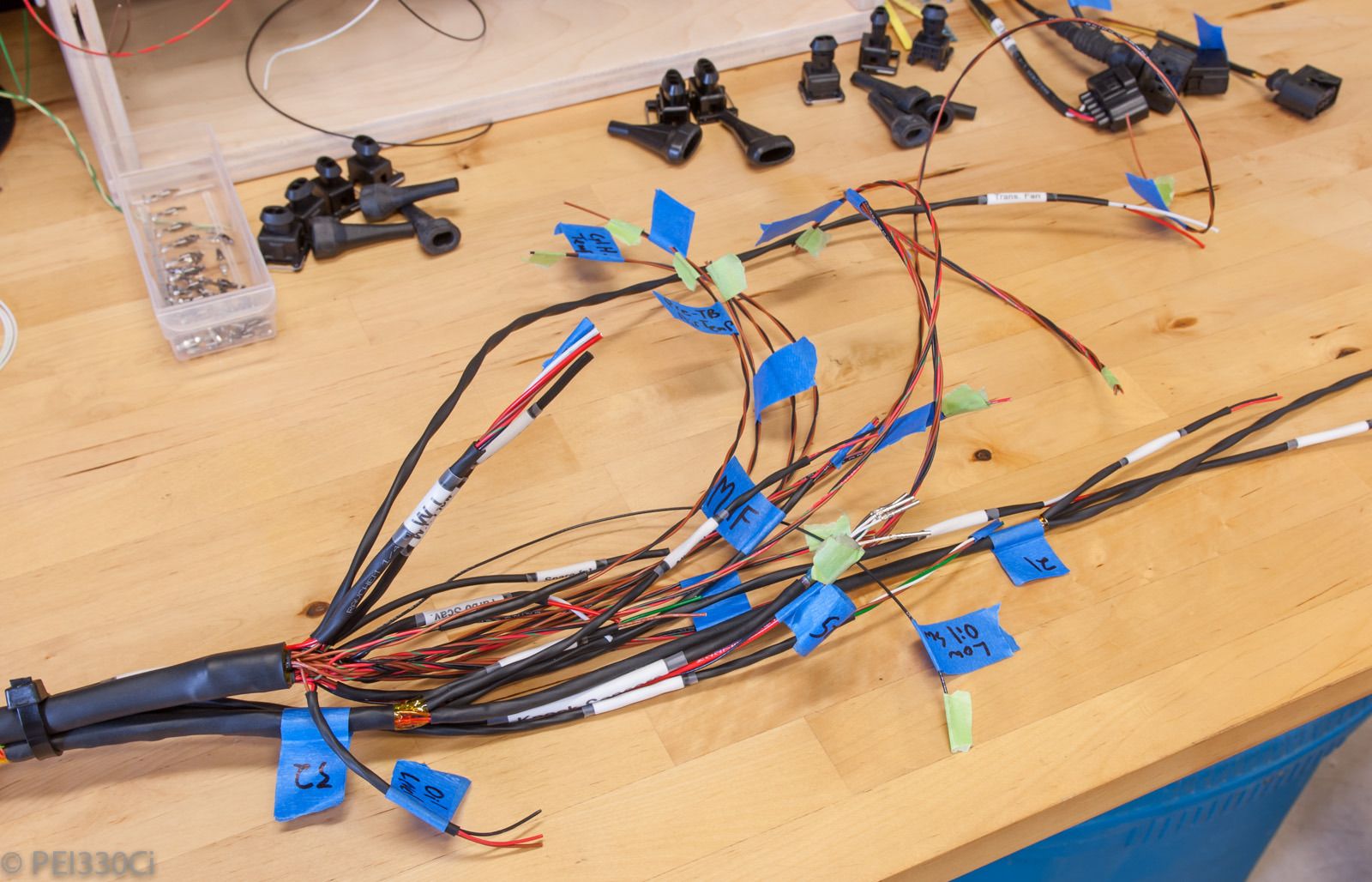
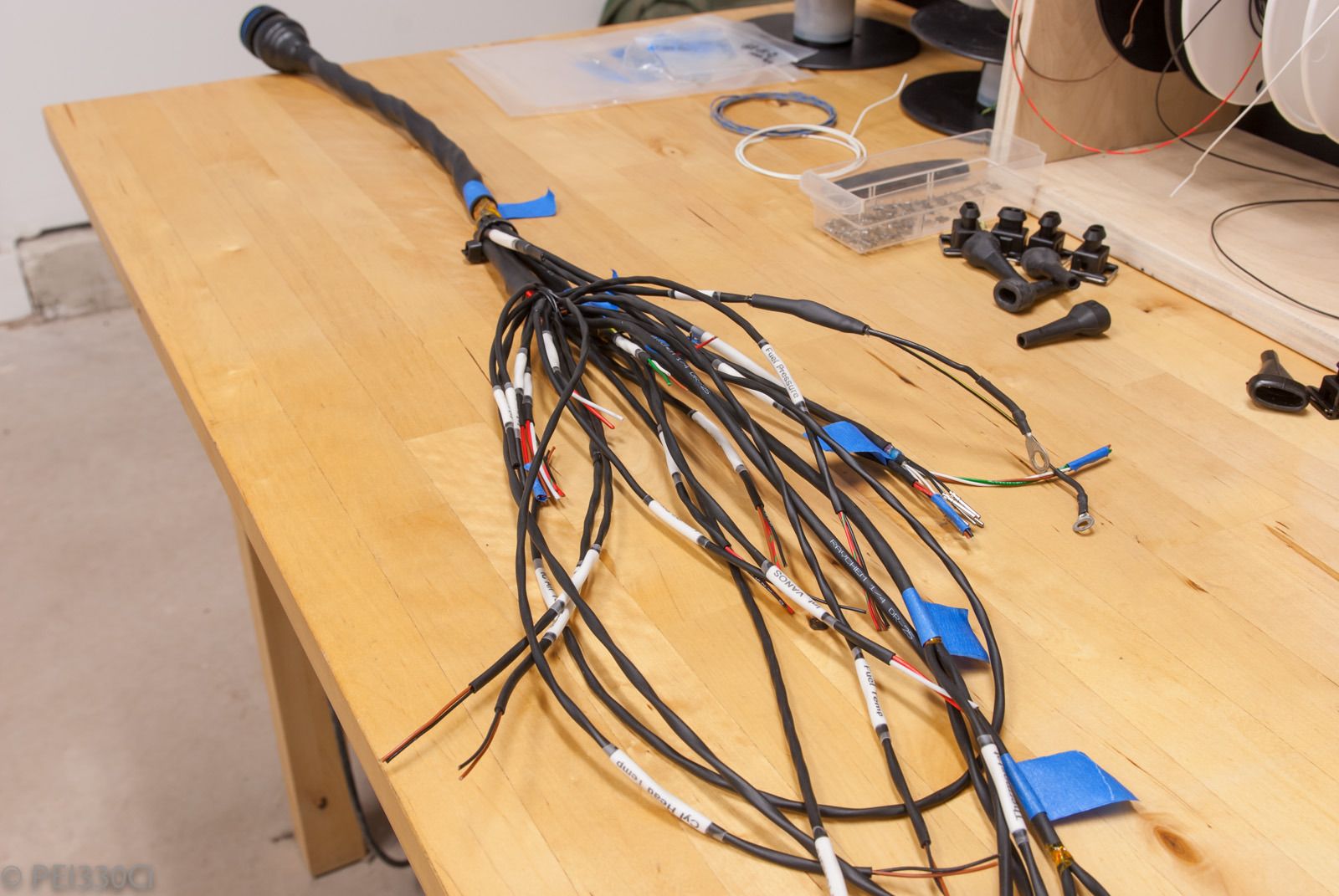
Right Engine harness construction:
Starting the Intake Manifold harness:
Ready for DR-25 on the first section:
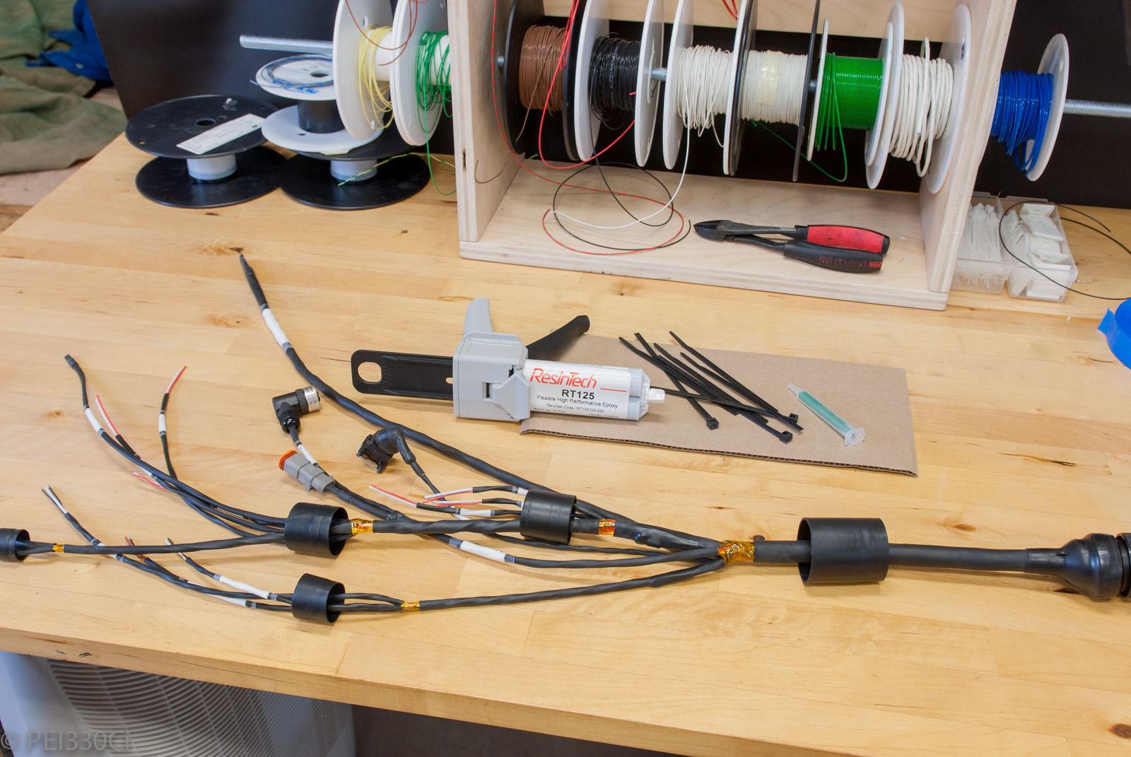
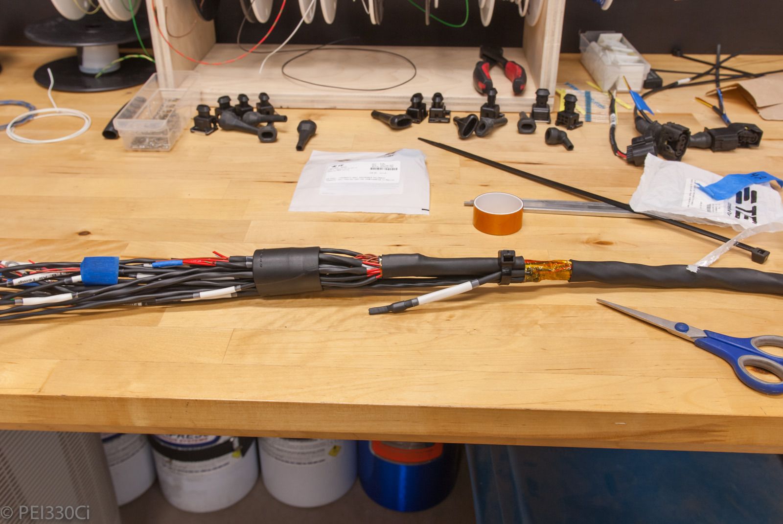
Prep before applying RT-125 to the heat shrink boots:
Set up to apply the glue to the boots:
Done:
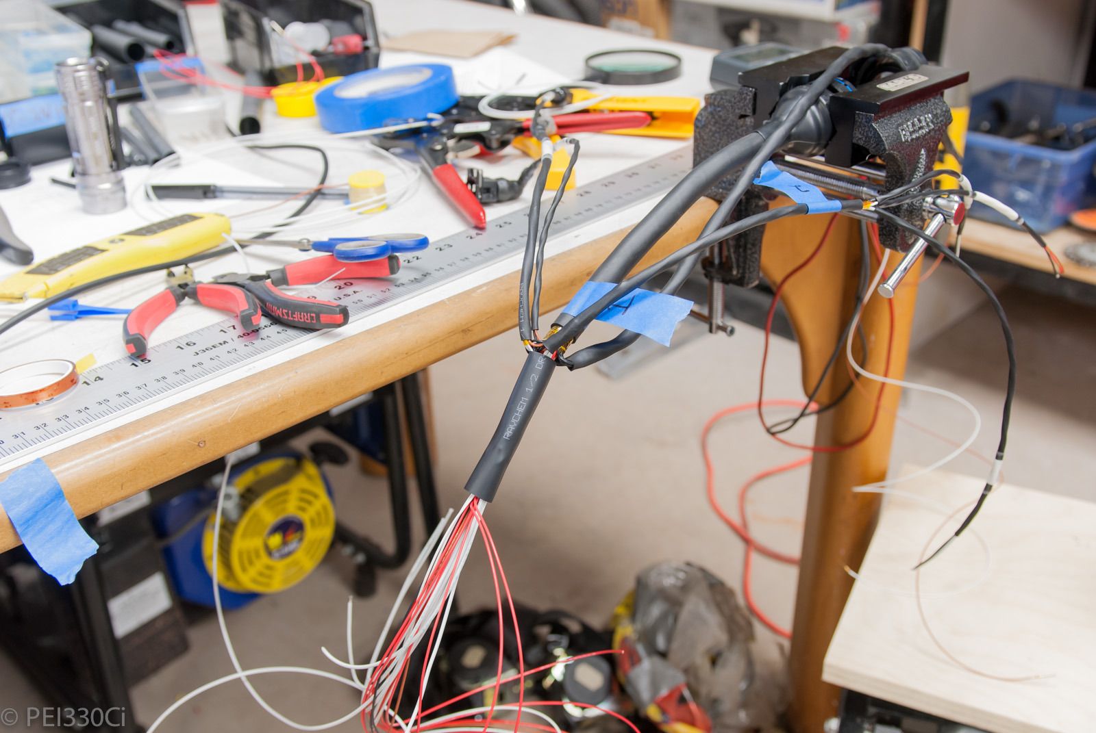
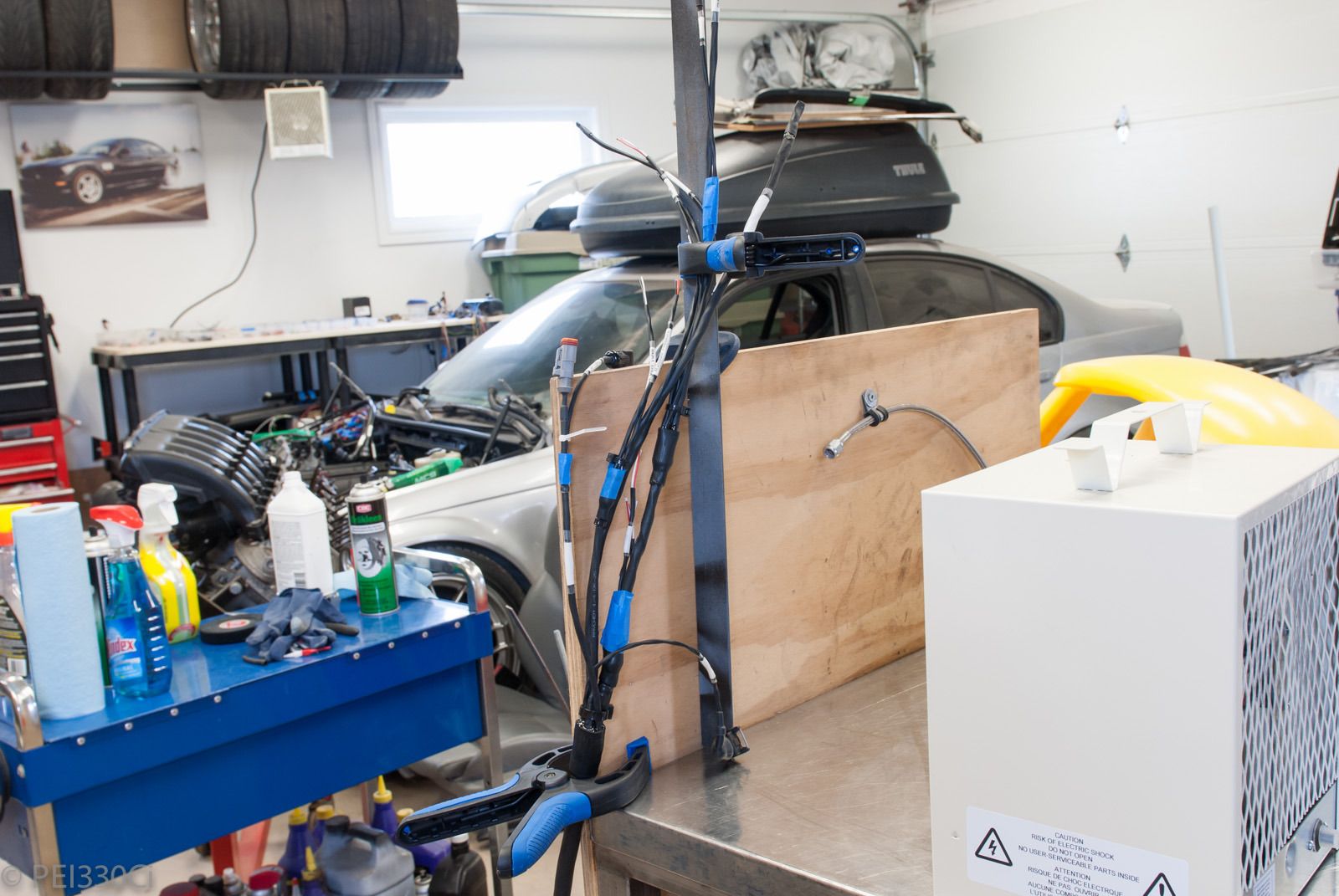
One thing about working with RT-125 is that it has a really long cure time. At room temperature, we're talking hours and it has the consistency of honey. What I'm getting at is that it will run all over the place unless you have it contained, or accelerate the curing process with heat. In the first image above, you can see the 5kw heater that I use to raise the temperature of the connectors for about 30 minutes to accelerate the curing. The result: Not much mess.
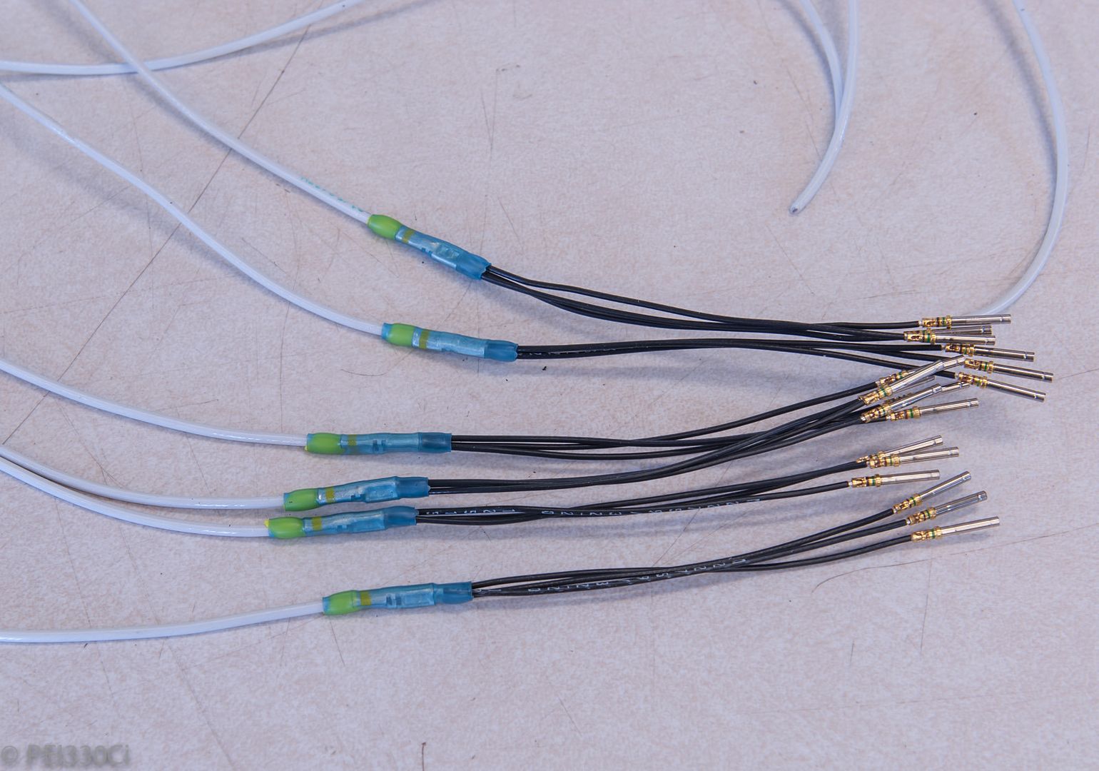
When running a high-current signal through a connector with only 20 awg pins, I bundle together groups of pins to meet the total current requirement. 14 awg wire terminated to 3 X 20 awg:
That's it for now. Next week I work on completing the Intake Manifold, Left Engine, and Right Engine harnesses. Then there's still the dash center console area, Right Bin and Left bin to finish before I can turn the power on. Weeks of work ahead....
Luchador
Love love love the detail.
Light Fires N Burn Tires
Your attention to detail is incredible. I feel like taking this much time on just one of the wiring harnesses would drive me crazy. Keep up the great work!
M54B30 Inside
There is no way I could focus on the harness exclusively, or it would drive me crazy as well.
Usually, I try to do "one thing", and then walk away. That one thing might be a bundle of wires, a few pieces of heat shrink, or even just a single connector. If I feel that the task has been done properly, I move on to the next thing. Often though, I'm not happy with something, so I either end up re-doing some part of the task, or starting from scratch. With practice, the re-work is reduced, but there is a LOT of material that ends up in the garbage bin.
One trick that I use, is to track progress in a spreadsheet of individual tasks. If there'a 0.01% progress, I still feel like I'm getting somewhere...
License Revoked
Real bosch motorsport part numbers start with a "B" your injectors are production parts.
Member
Looks good Adam. I came across some old pics that I think you'd appreciate:
Wiring by Jon Kensy, on Flickr
Wire Rack by Jon Kensy, on Flickr
Former job (defense contractor) was THROWING OUT raychem everything that didn't have lot IDs for traceability! This meant I picked up 100', 500', 1000' spools of everything from 2 - 6 conductor shielded PTFE jacket, 14 - 20g, dr-25, various braids (including copper and stainless braid). The rack is just something I whipped up to hold about 1/2 of the spools. I need to come up with another clever way to store it as its too big and takes up too much space and doesn't hold all of it. I priced out some of the spools and its dizzying.
Lurker
BMW CCA Member
If its still in use,Hang it from the ceiling?
-Ed Hands
MaxPSI Stg2 Turbo
R.Forbes magic F&R
100K Original owner miles.
Proud member of the BF.c FI - Big Torque Club (>500wtq Dyno Results)
Member
It's the only way task oriented people like us can stay sane on a big project. I don't go as far as keeping a spreadsheet but I think all week about what I will work on next and then once that is done, I pack up and leave. Sometimes I still catch myself standing in the middle of the garage for a good 10 minutes just looking around. I didn't even realize I do it until my wife noticed. She asked, did you go full retard? Huh? You've been standing there zoned out forever... It doesn't feel that way to me since my brain was going supersonic thinking about what I still want to do, then remember something else, my eyes wonder there, and it goes on.
Sometimes when I have a big step next that is unlikely to be finished in one day, and breaking it down into sub-tasks is so unsatisfying that I just don't start. It took me a long time to get past that hump with my fender flares, especially the first one. I've never done what I was planning before and there was a lot to do before it looked and felt like I did anything.
Keep on keepin' on.
M54B30 Inside
Drool!
That is a serious stock of wire; you won't run out soon!!!!
Yes, it's expensive to buy this stuff, but once you work with Spec 55 wire, you have a hard time using other stuff.
Member
Yep - back in my MS days wire was wire. Now I won't touch it if it isn't Raychem. I do probably have enough to rewire 10 - 15 cars lol. It definitely won't go to waste just wish the spools weren't so damned big.
M54B30 Inside
Sometimes progress is simply figuring out what to do.
I've had some things I couldn't figure out for months, then one day it just clicked. That can be just as rewarding as seeing physical progress at times....
M54B30 Inside
Need to add more than 3 X #18 awg wires into a 12 awg butt splice?
Add a #10 awg barrel onto one side:
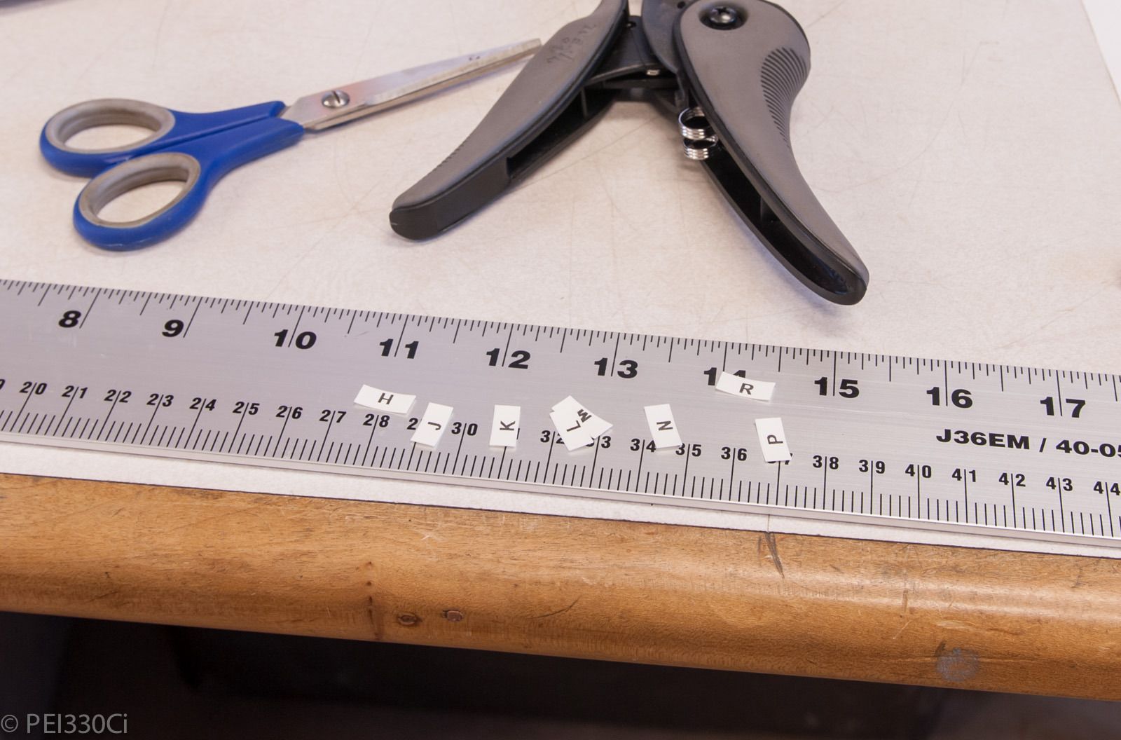
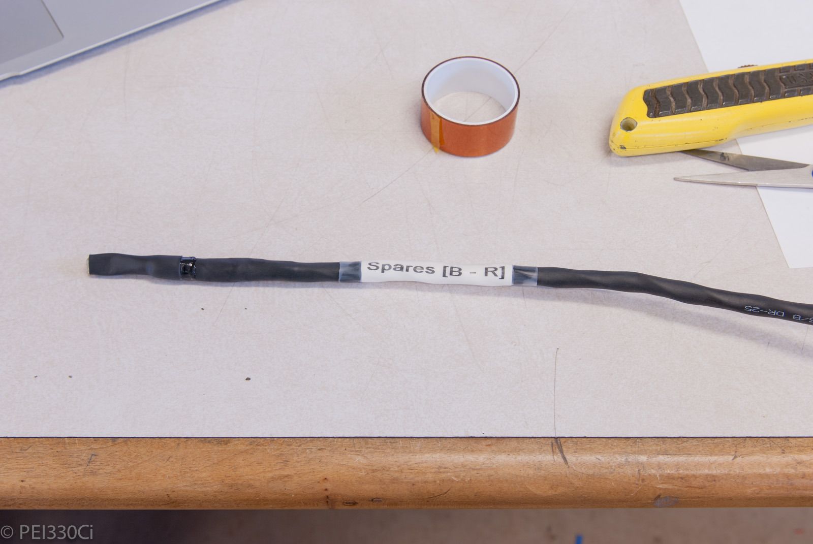
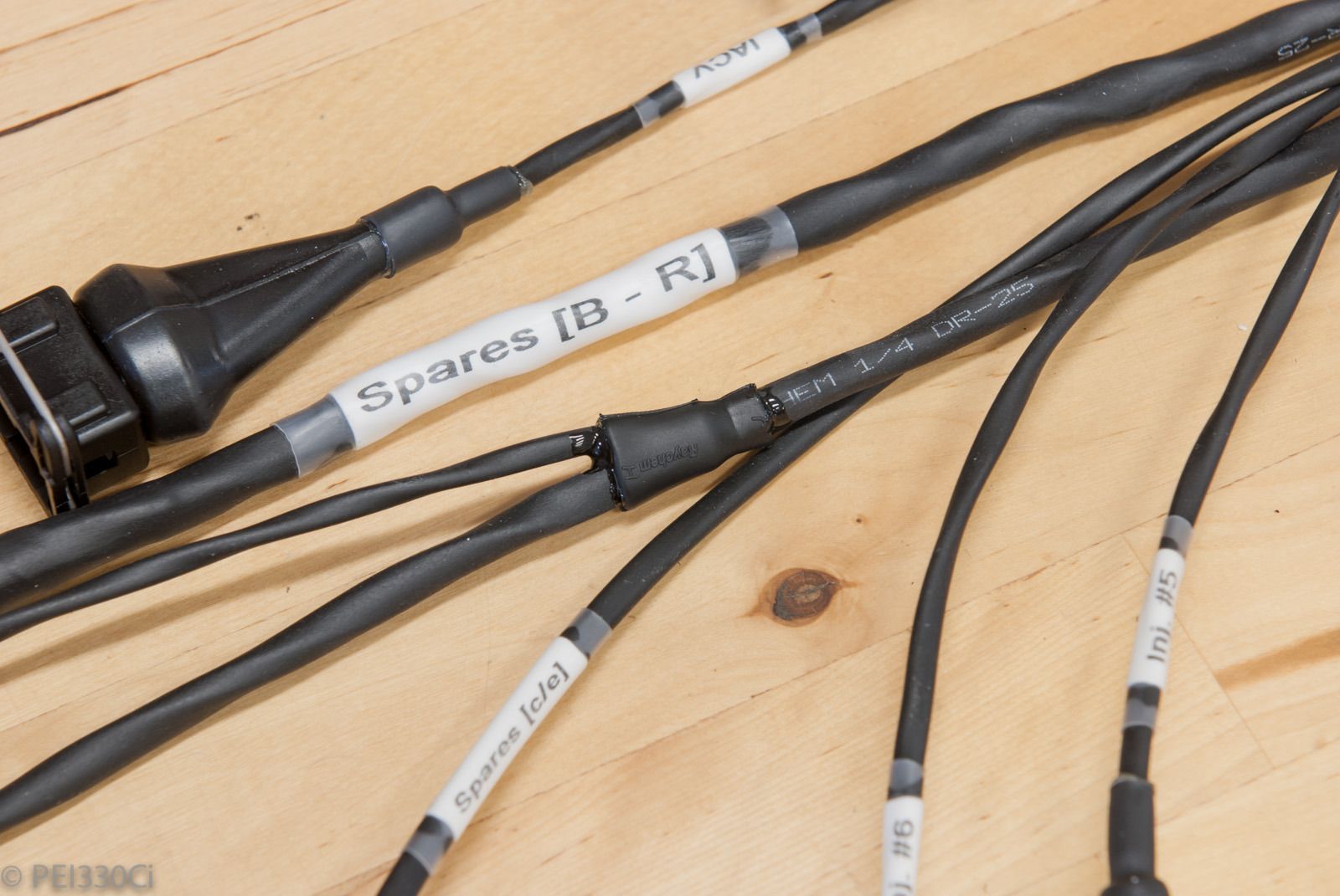
Labels:
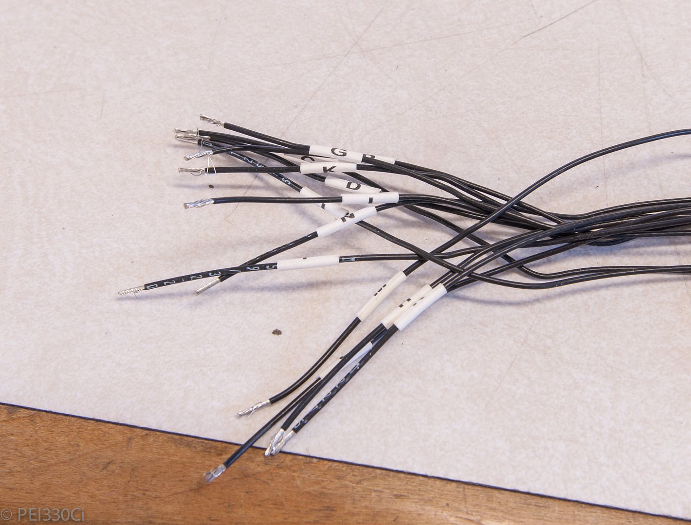
... for #20 awg spare wires in the harness:
All the spare wires for future expansion are bundled and labeled for ease of use later.
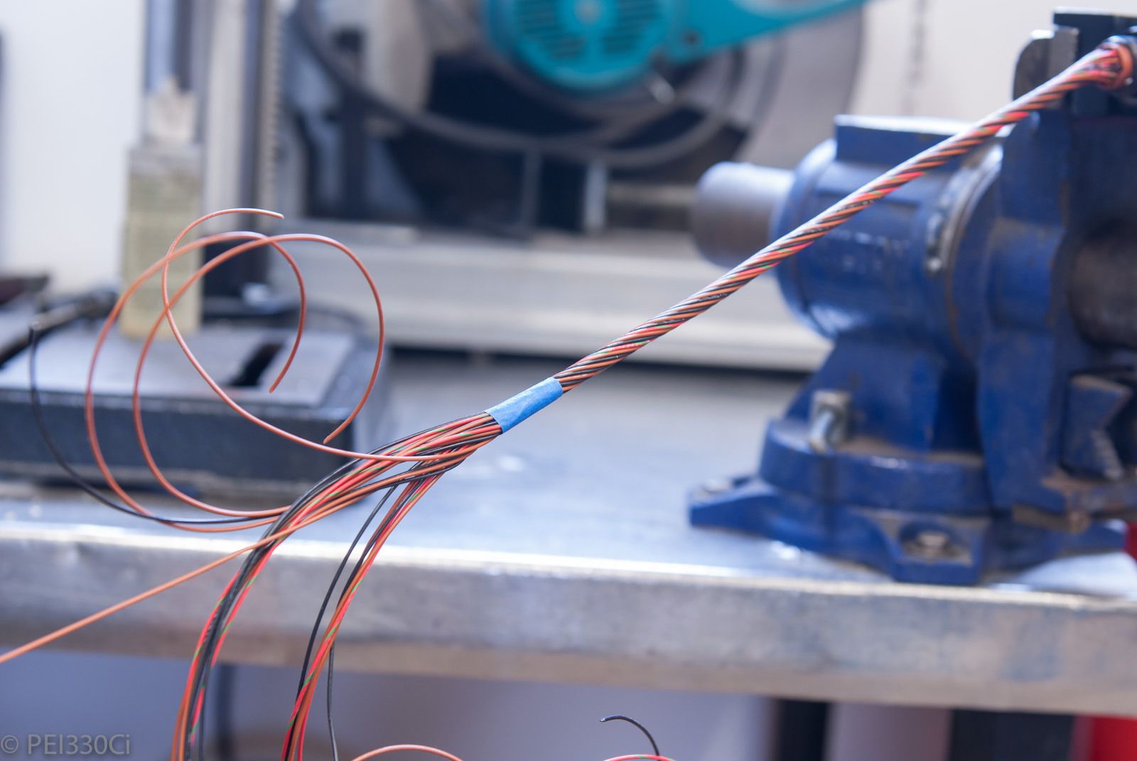
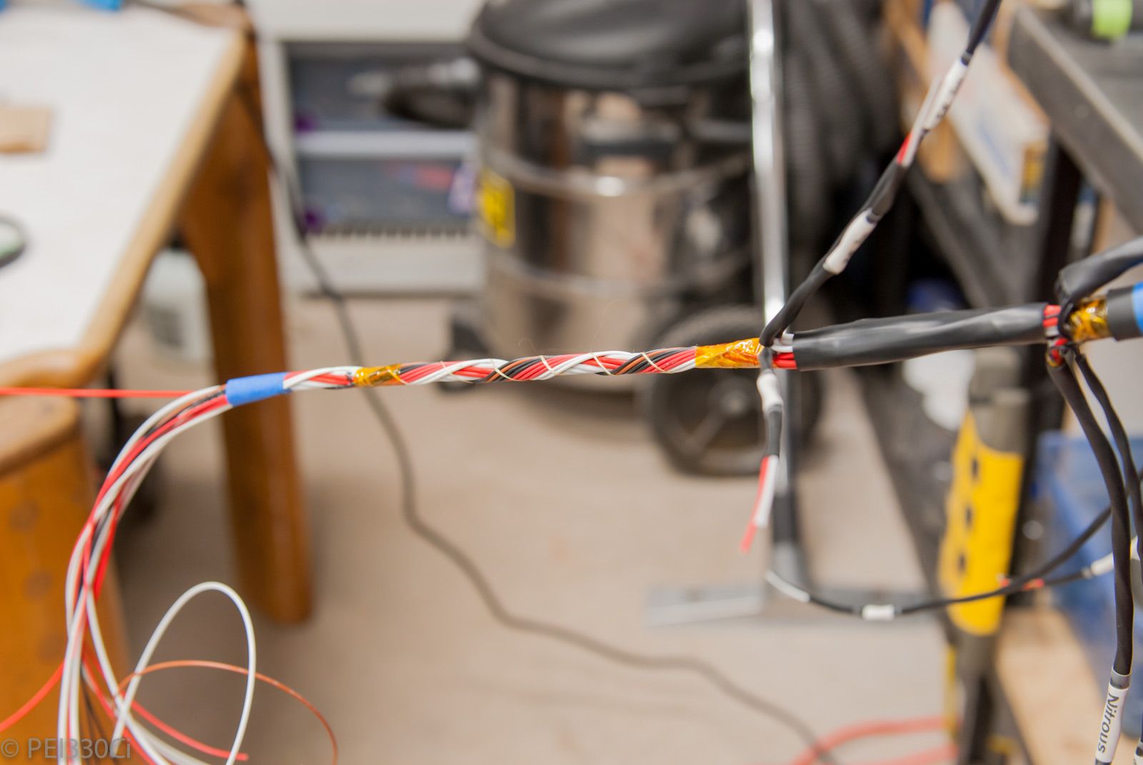
Concentric twisted:
Ready for heat shrink:
Done:
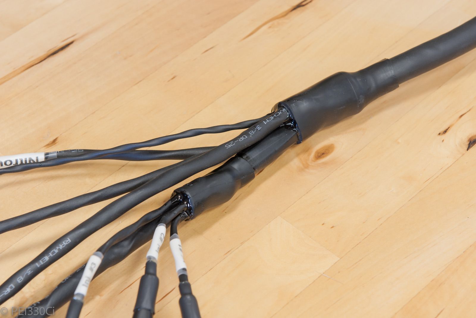
Continuing with transitions:
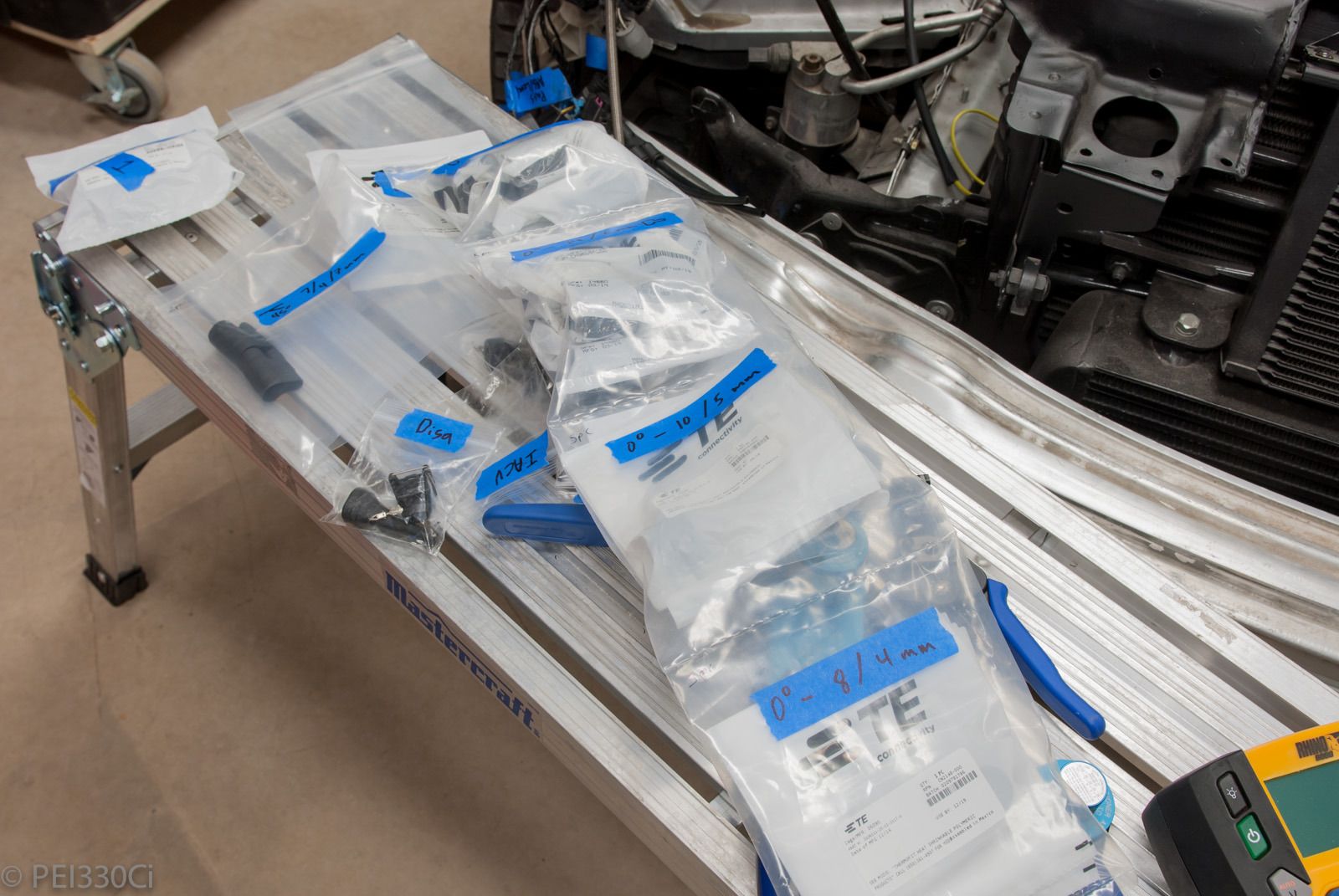
M54B30 Inside
Bags and bags and bags of Raychem transition boots:
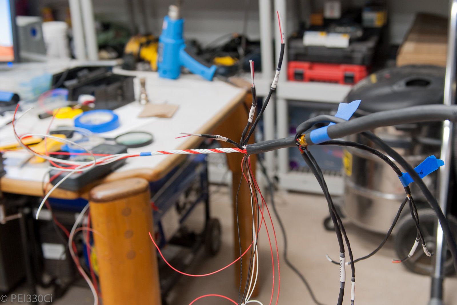
Concentric twisting the next section starting with #14 awg:
#20 awg wires added and laced:
Much much further along:
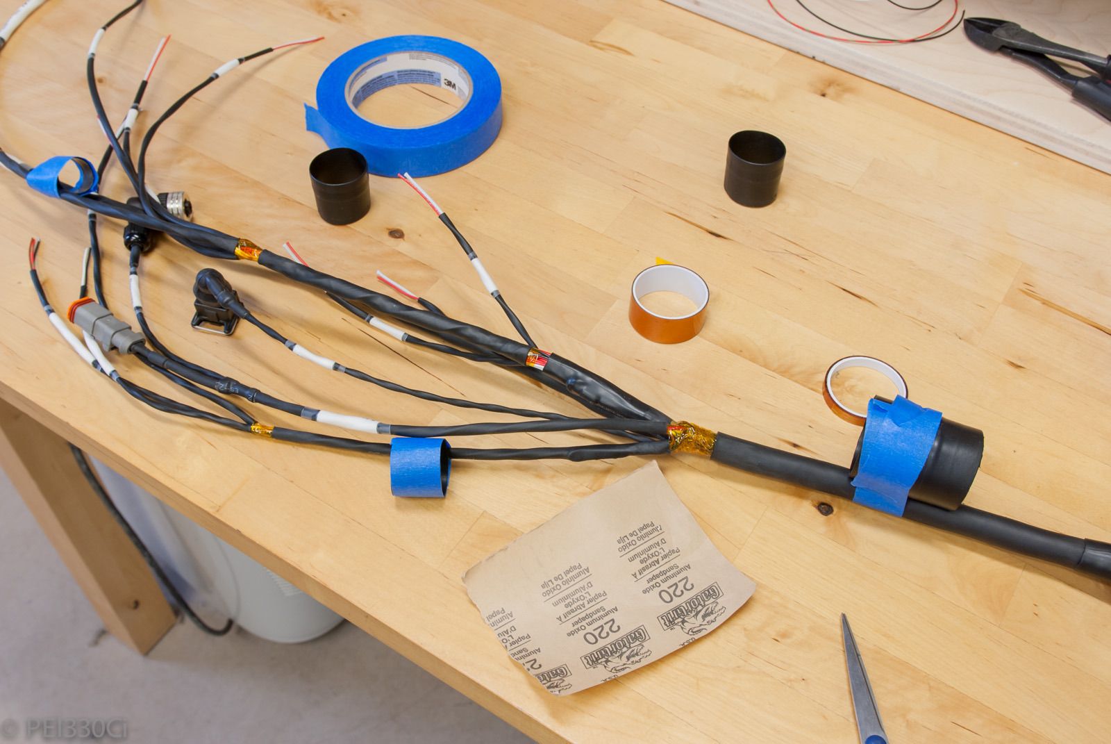
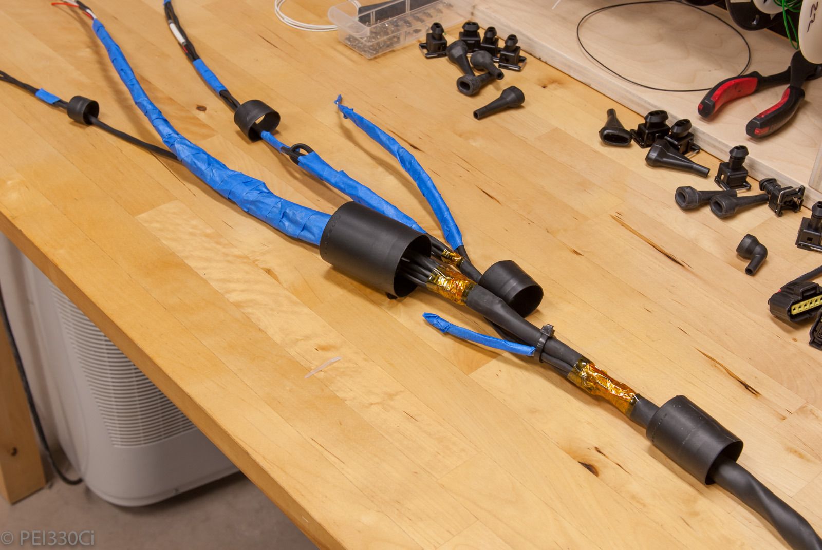
Prep'ing for RT-125 and transition boots by wrapping exposed wires with Kapton tape, and scuffing the DR-25 with sandpaper:
Ready for the boots:
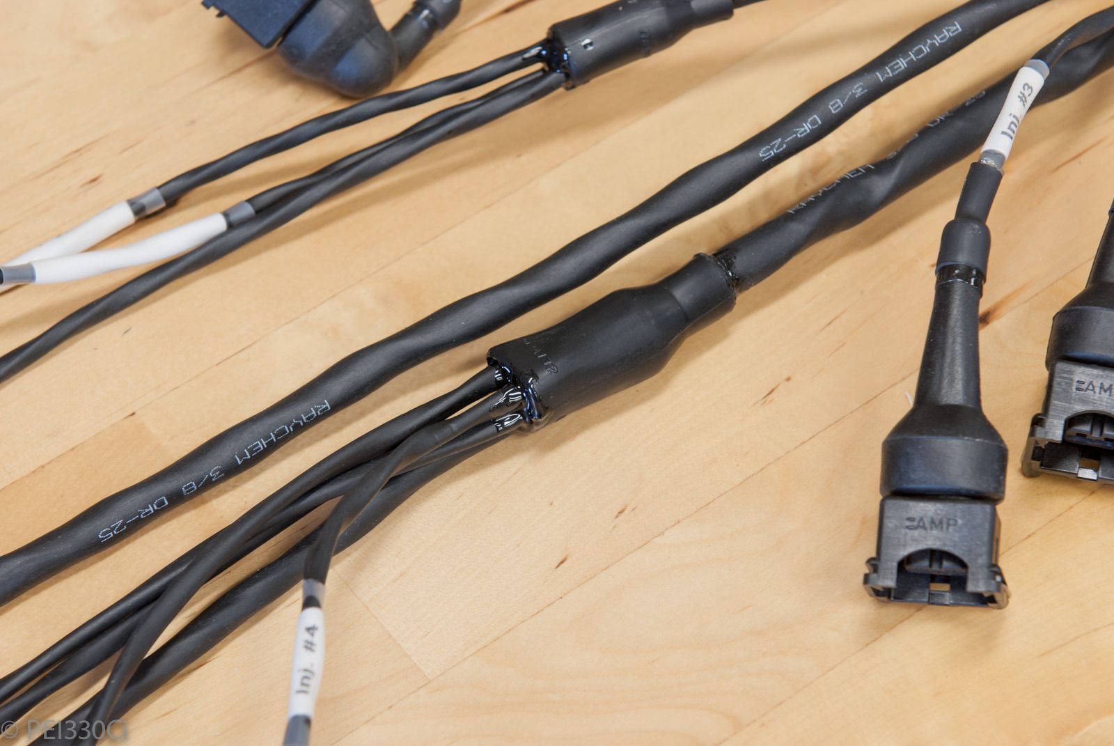
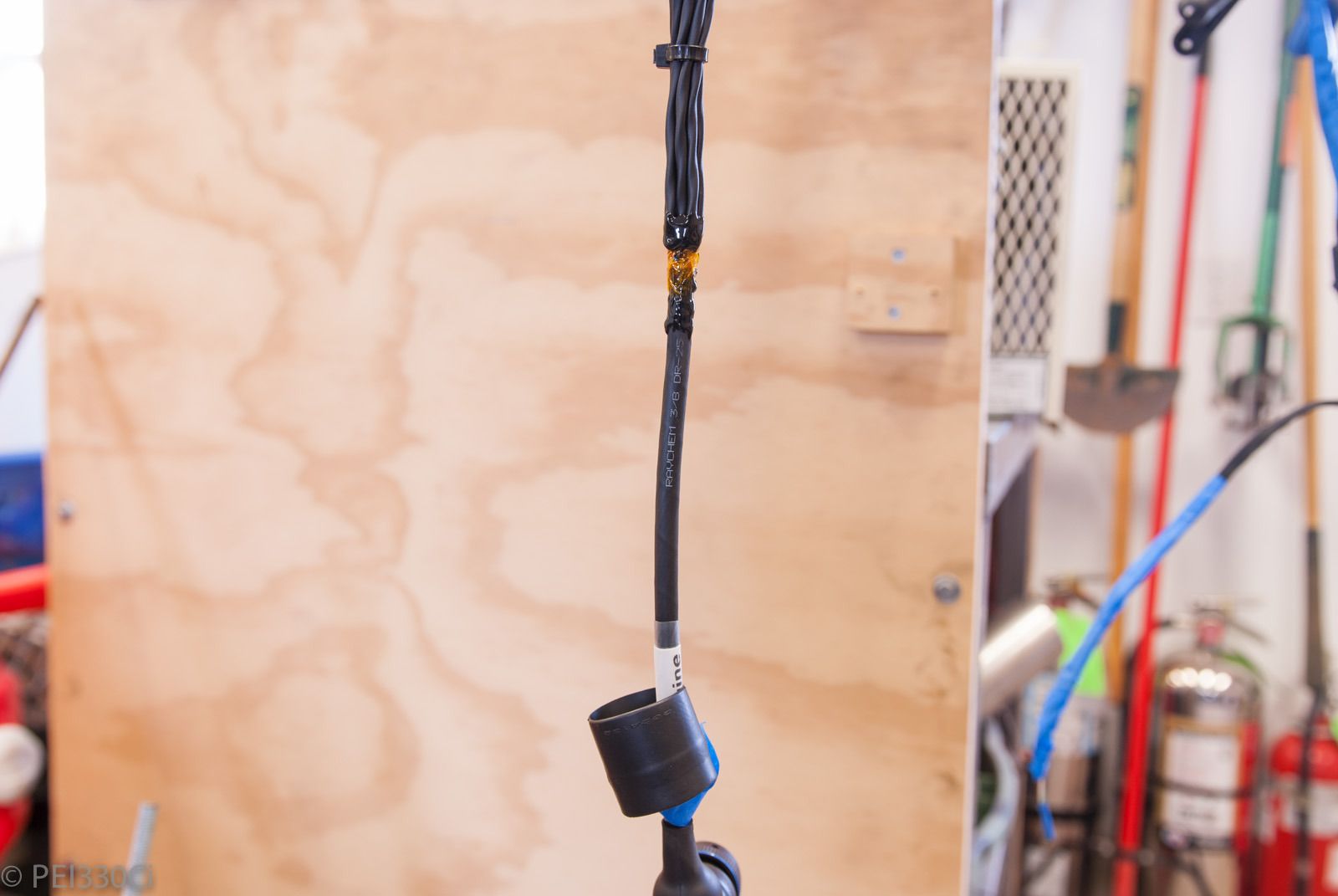
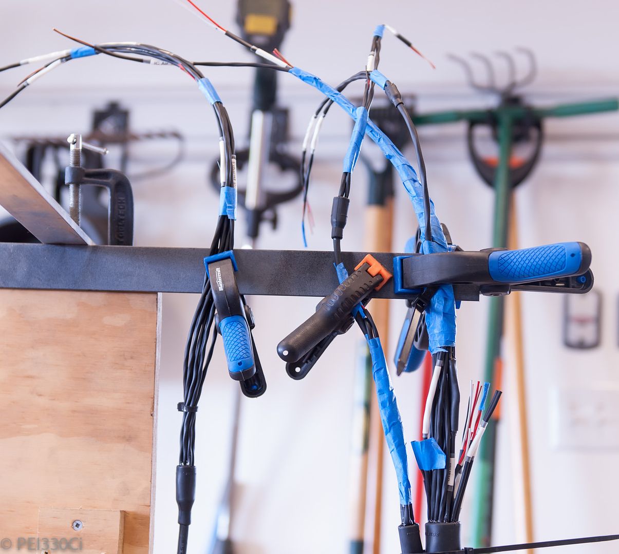
Curing the RT-125 with heat:
The harness is suspended to keep the RT-125 from running out of the boots before it's cured. When warmed, this stuff is like honey....
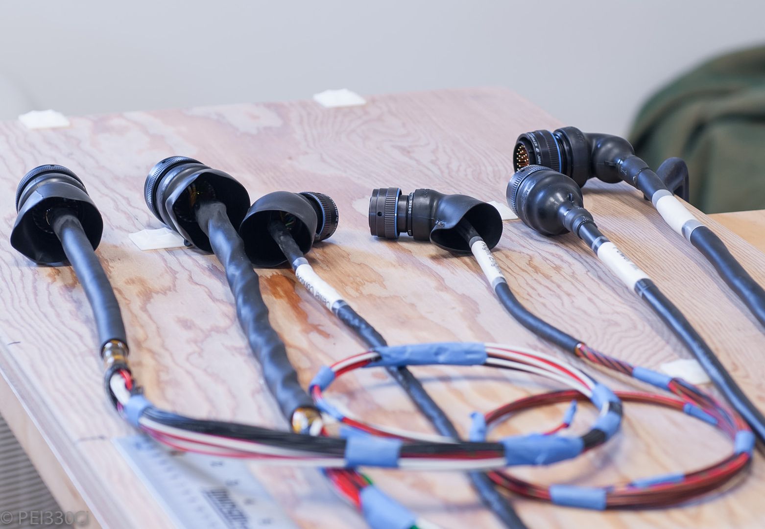
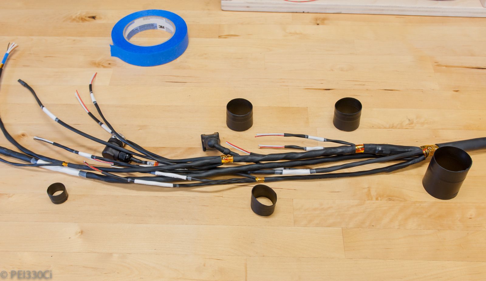
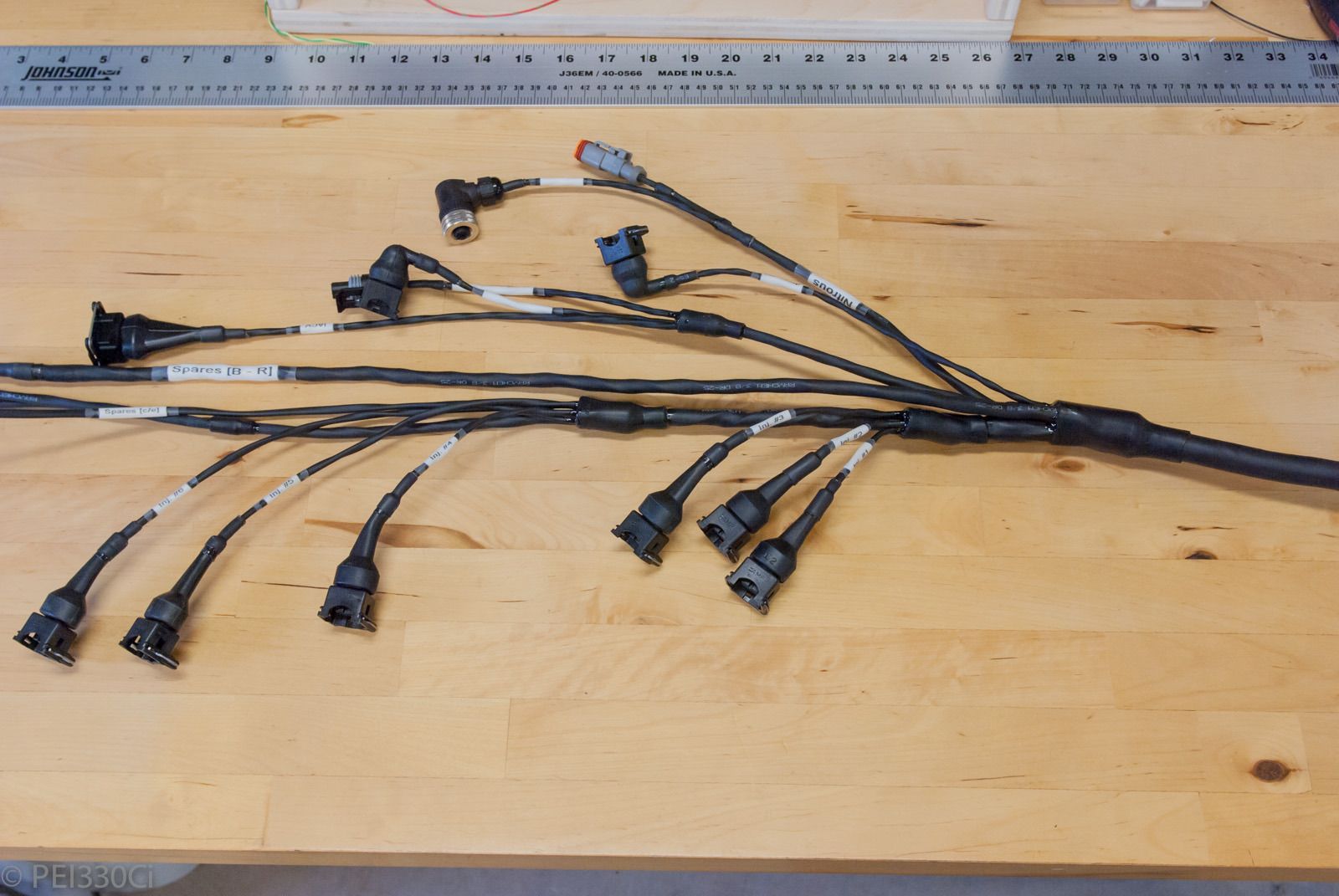
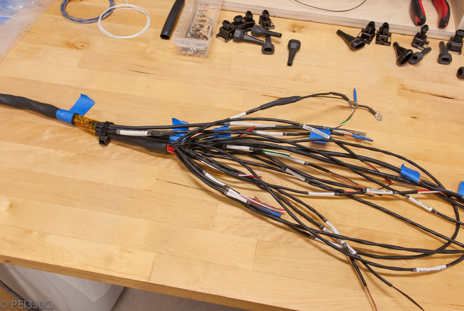
Terminating the segment ends with connectors:
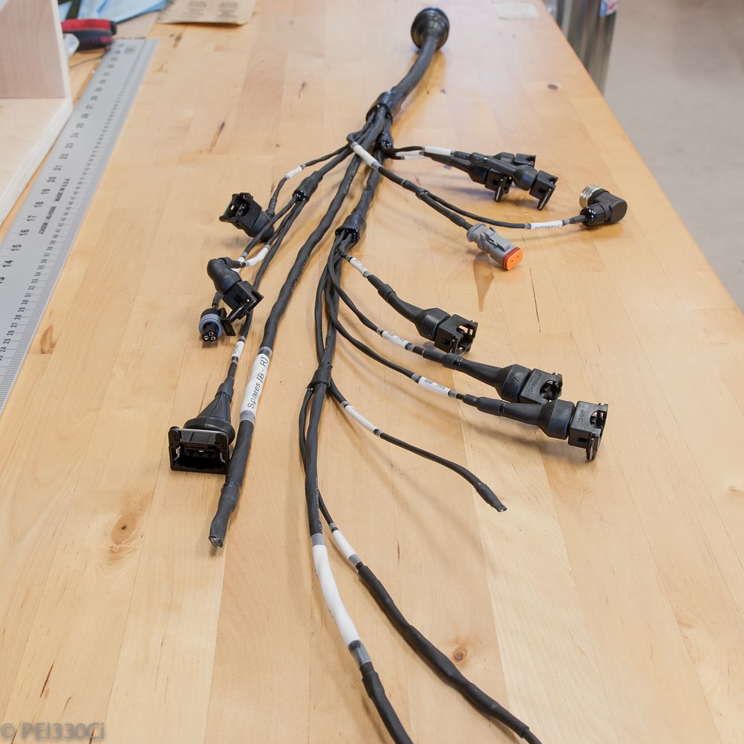
All done:
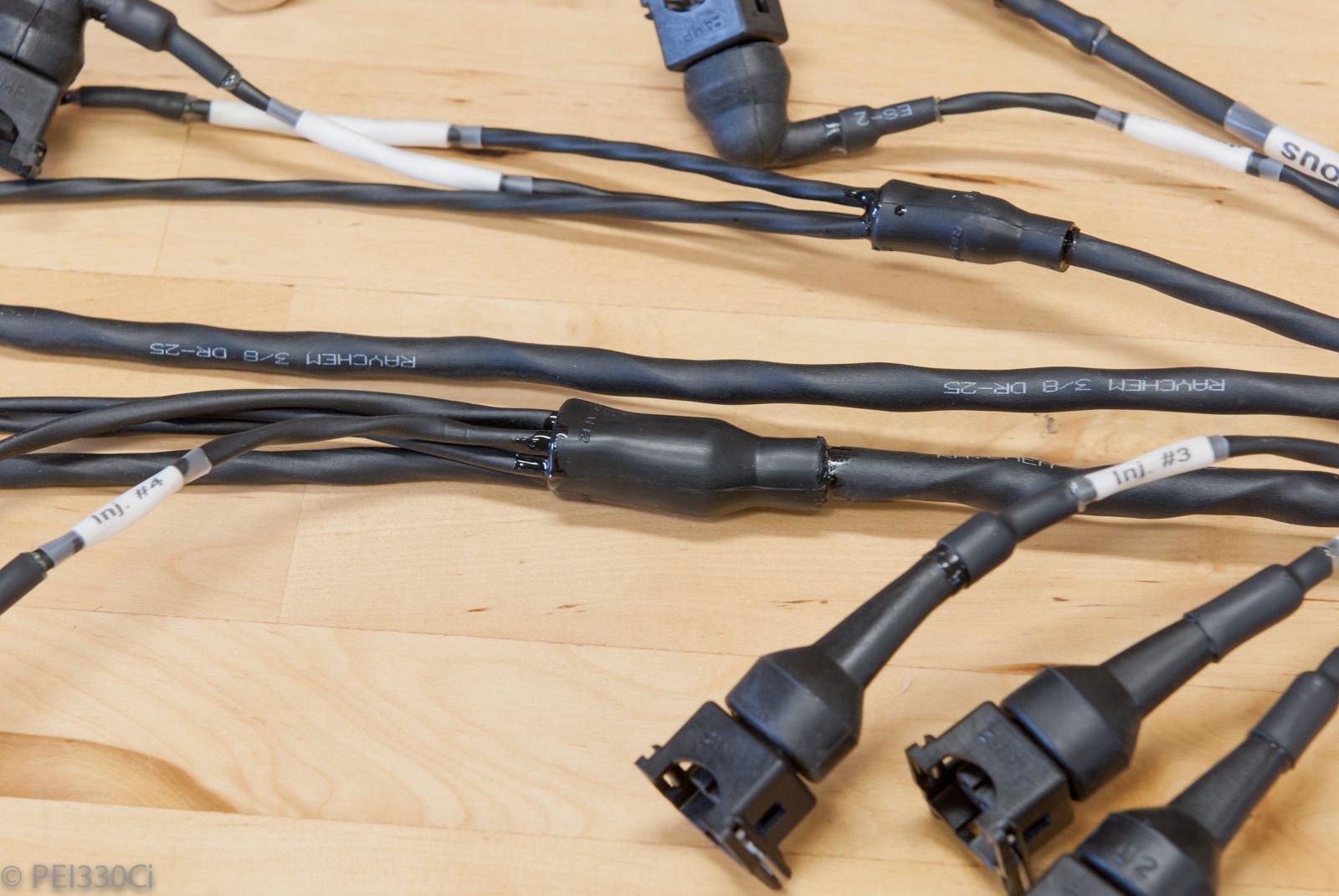
Raychem transition boots sealed with RT-125:
Ready to be installed:
From a time perspective, this harness has probably got over 30 hours of planning, prep, and assembly.
Member
man, your attention to detail is incredible.
i wish i had the bank account to endeavour on something of this calibre.
what catch-can are you running, sorry if its already been said.
WTB:
S50/S52 cams + trays
Rallyroad 60mm gauge holder + 52mm gauge holder
M54B30 Inside
Everyone has different skill sets; I certainly don't have the discipline to do the fitness stuff that you do!
As for the cost: time is a big issue.
The catch-can is just a generic Moroso unit. It has worked fine, but I would prefer to have something that traps more vapour like the Radium pieces. Eventually I will go to a dry sump system, so the catch-can complaints will change....
Member
I agree, everyone has different disciplines.
I guess you're at the stage where you have a stable income, a garage and can spend the money required to get a project to the level of yours.
All my car work is done outside, swapping engines on the street, all work done on the ground, no fulltime job (uni student doing dual degree).
I love seeing guys on this forum build/buy their houses as much as i do their cars.
Thanks mate.
WTB:
S50/S52 cams + trays
Rallyroad 60mm gauge holder + 52mm gauge holder
M54B30 Inside
Continuing with the left side engine harness.
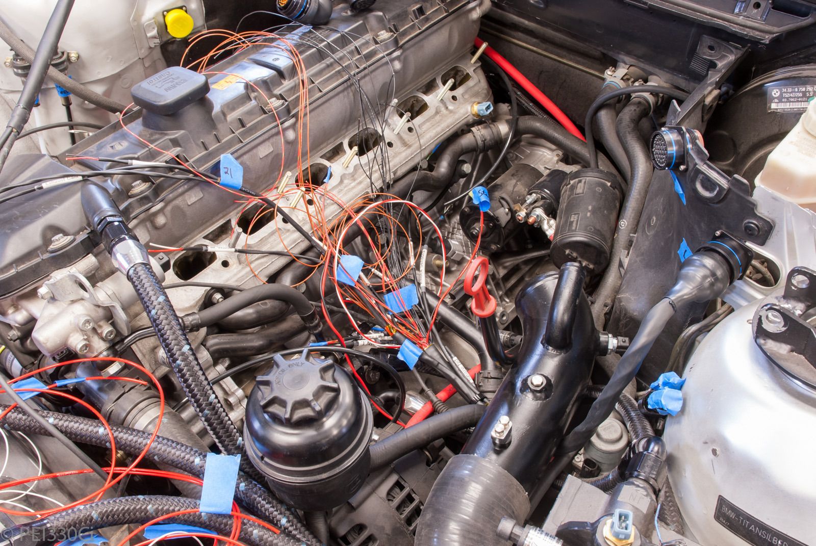
After the concentric twisting, I had to find which wires were for what. I used a DMM and test leads with milspec pins to find each signal wire:
One of the transitions to front of the engine:
Test fitting wiring:
Twisting signal wires with their mating ground and/or power wires:
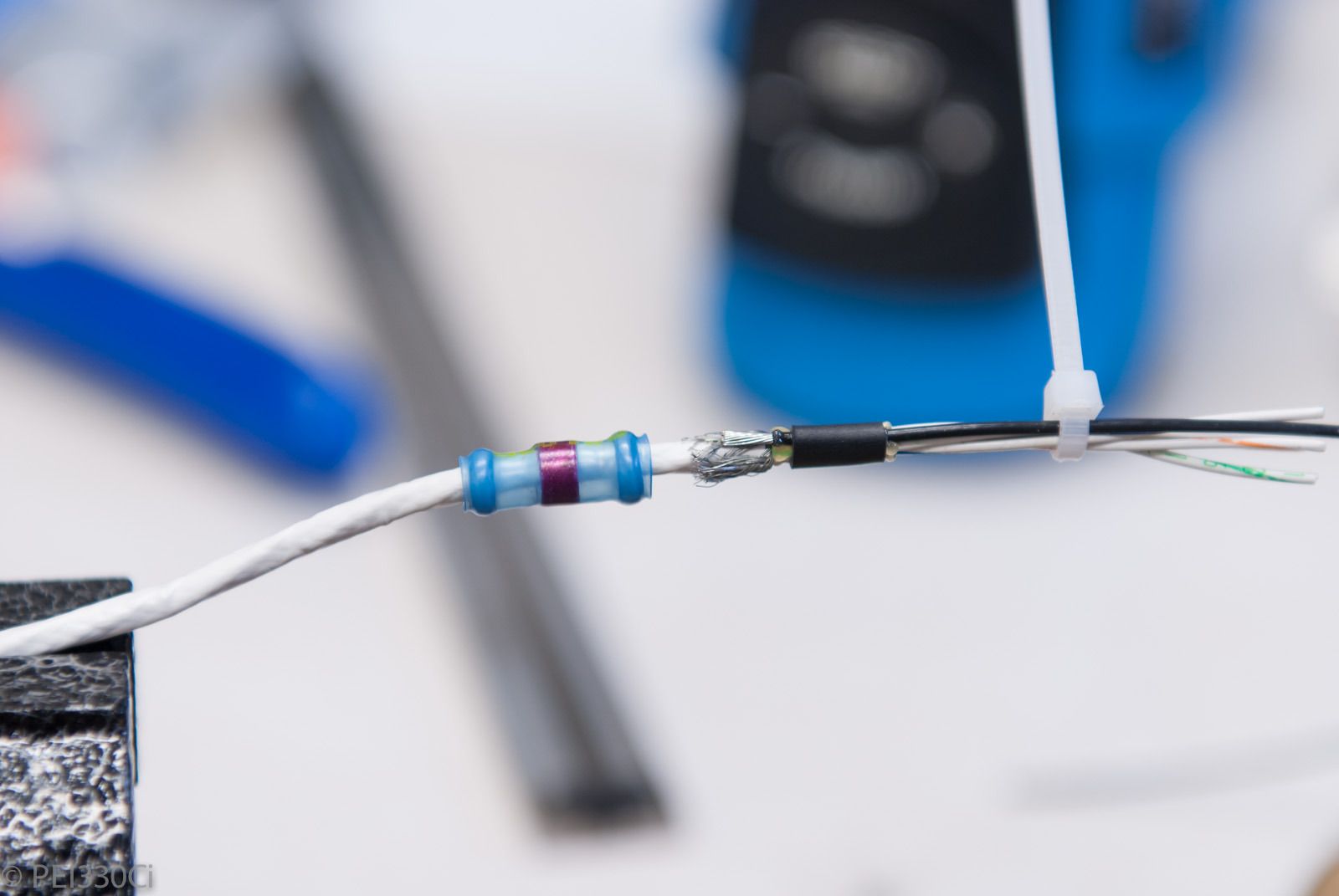
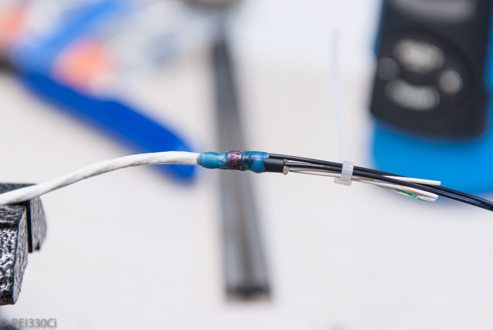
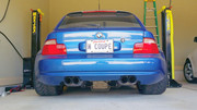
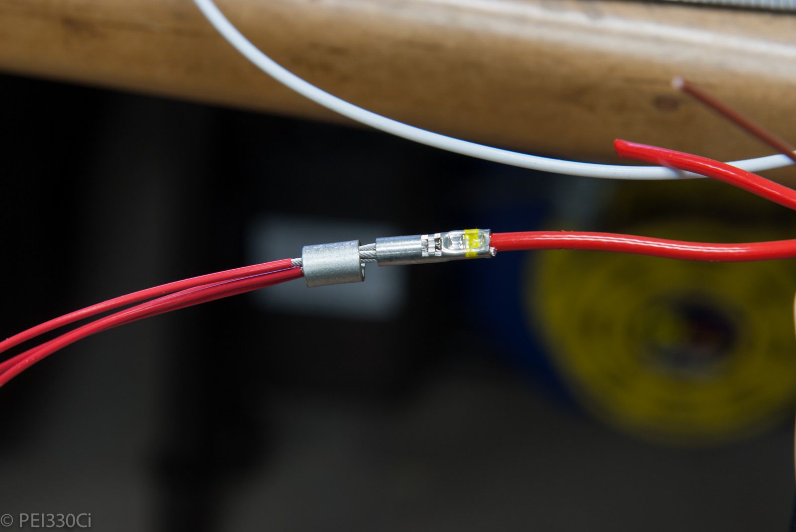
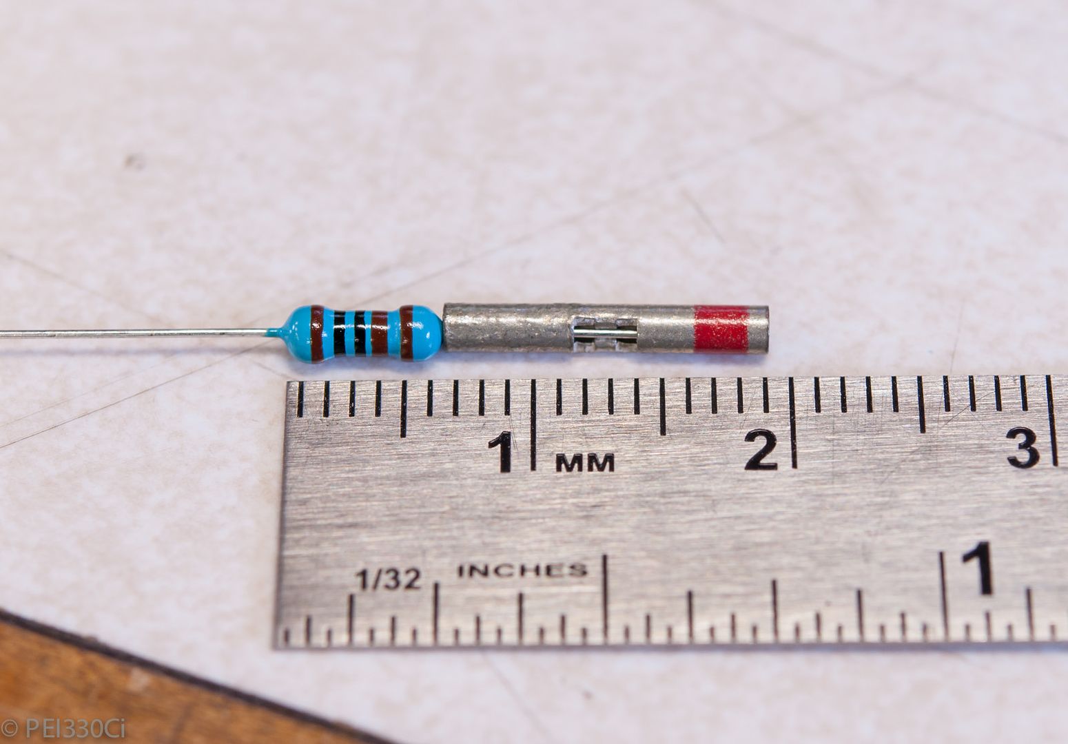
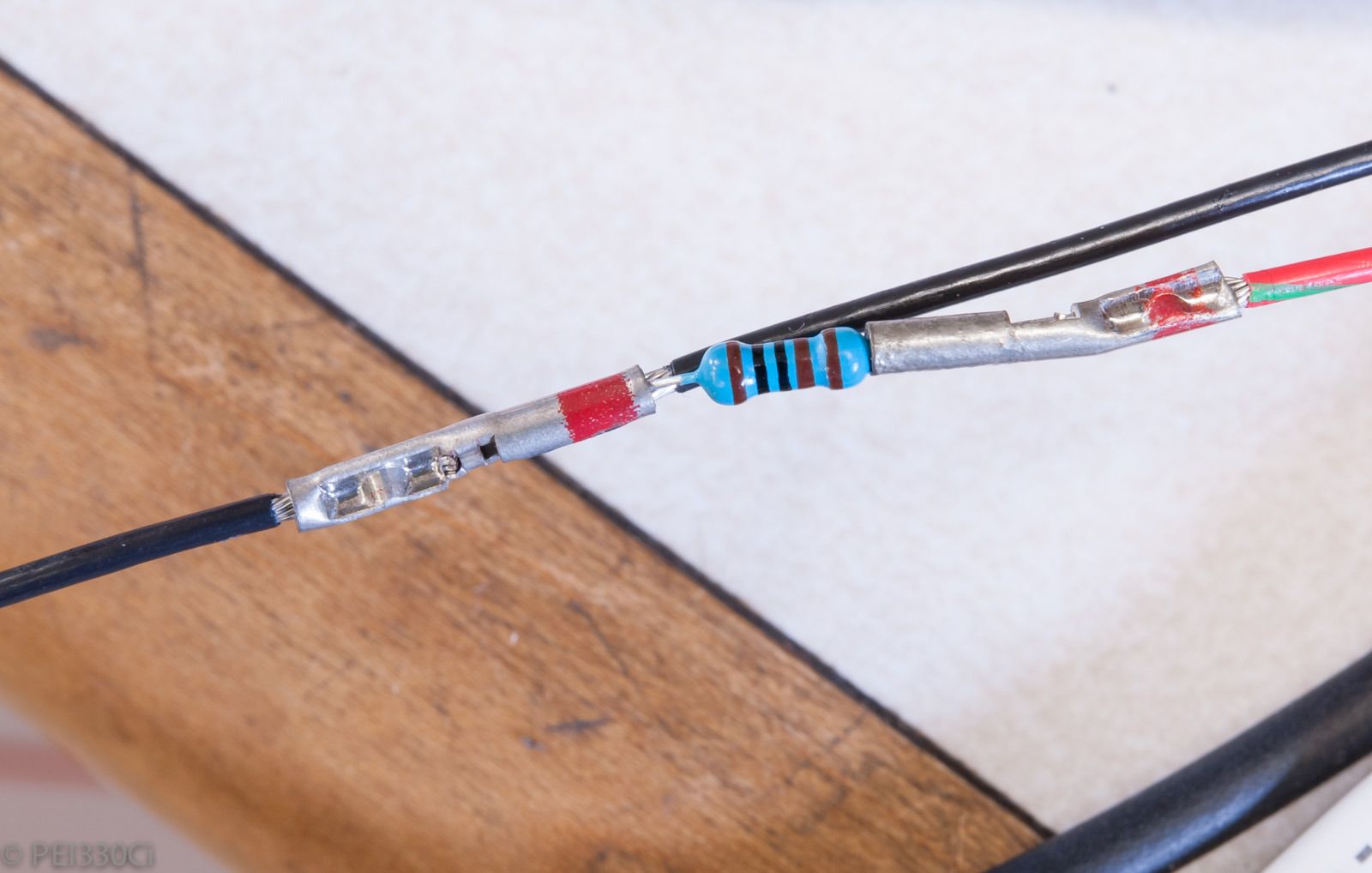
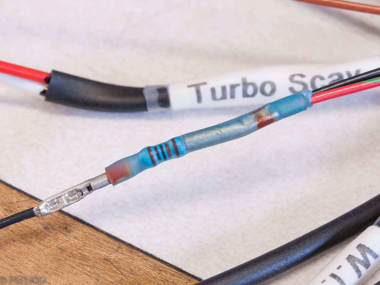
As I mentioned previously, I have to add pull-up resistors to a couple of temp sensor inputs. Below is the method I used to make a robust connection inside the harness between a 5V+ signal and the signal wire with a 1K ohm resistor. I should warn that I've used a Macro lens to show the details, and that the resistor would cover the tip of most person's pinky finger.
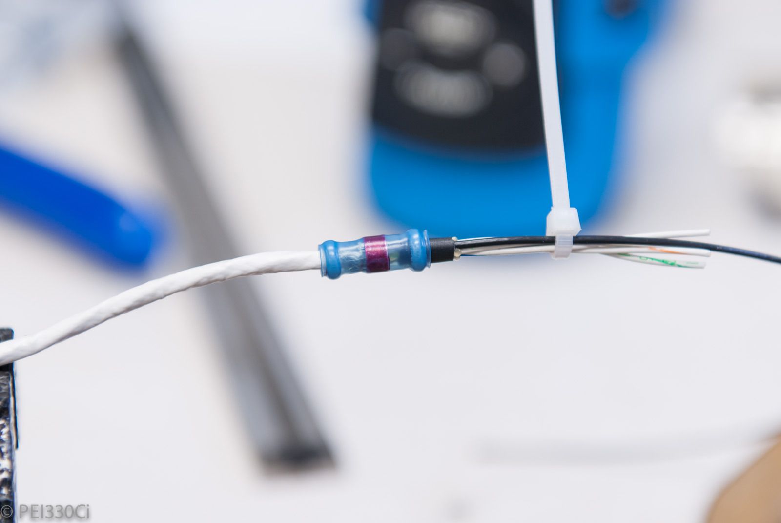
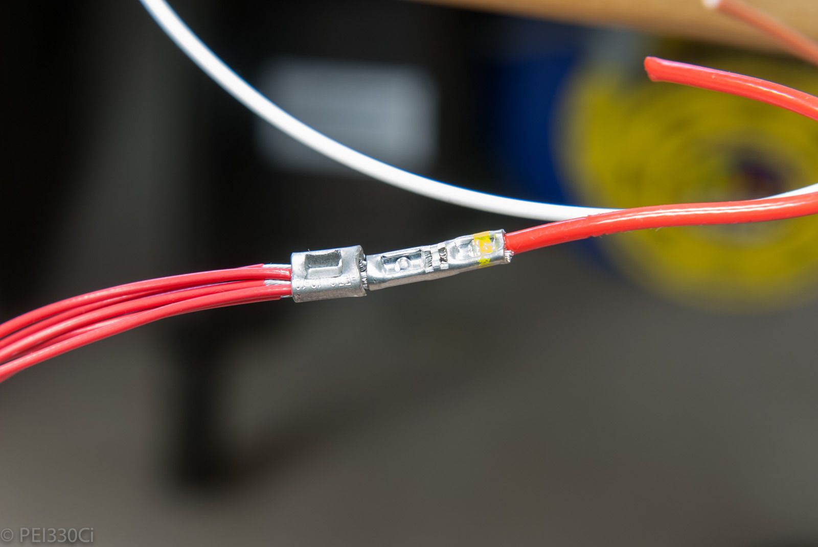
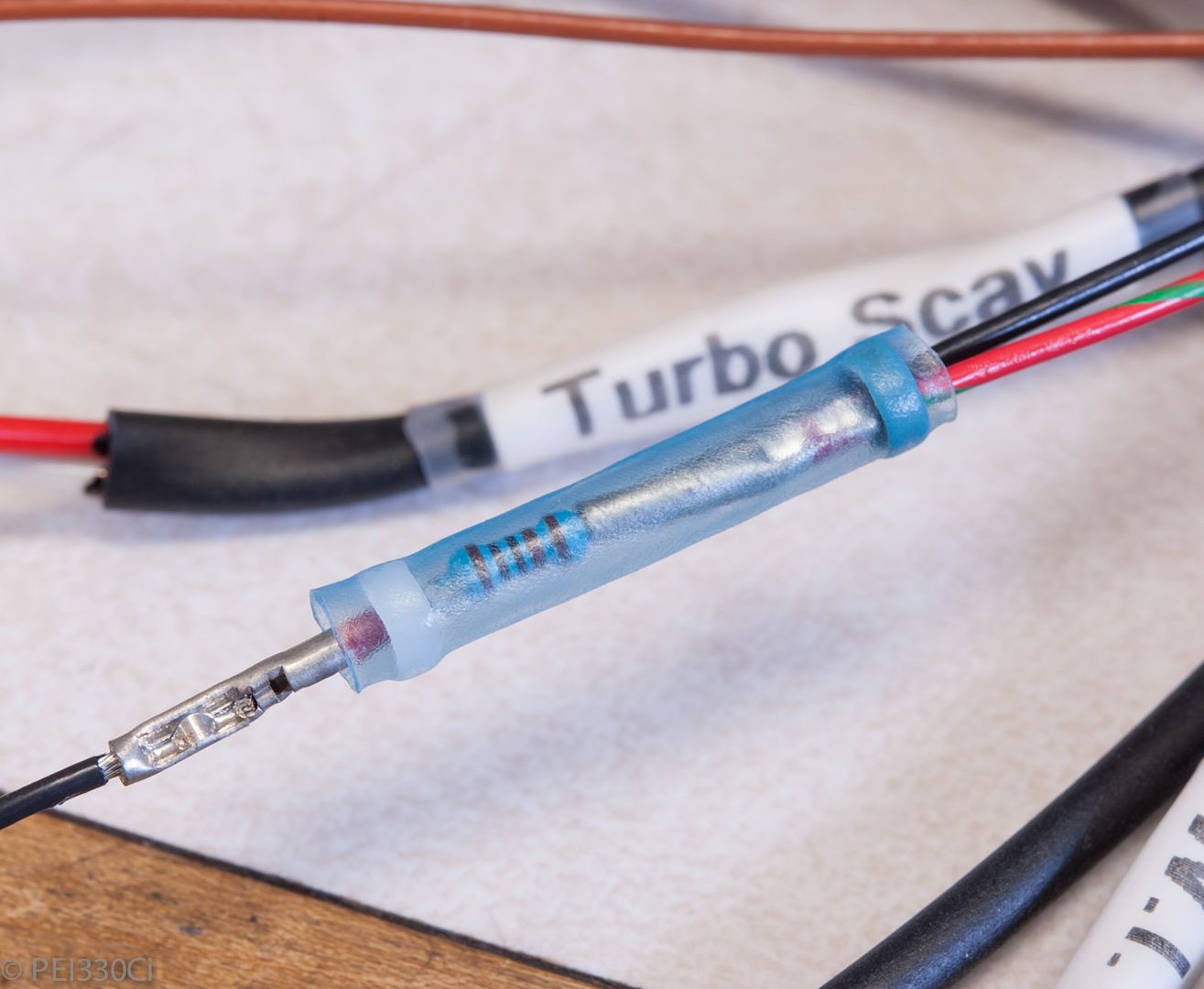
And finally, a "hard" glue lined heat shrink tube:
All the signal wires twisted and labeled:
Heat shrink added, as well as labels:
Prep'ing for Raychem transitions:
An example of a transition with glue applied before the Raychem boot is shrunk into place:
All done, and under heat to cure:
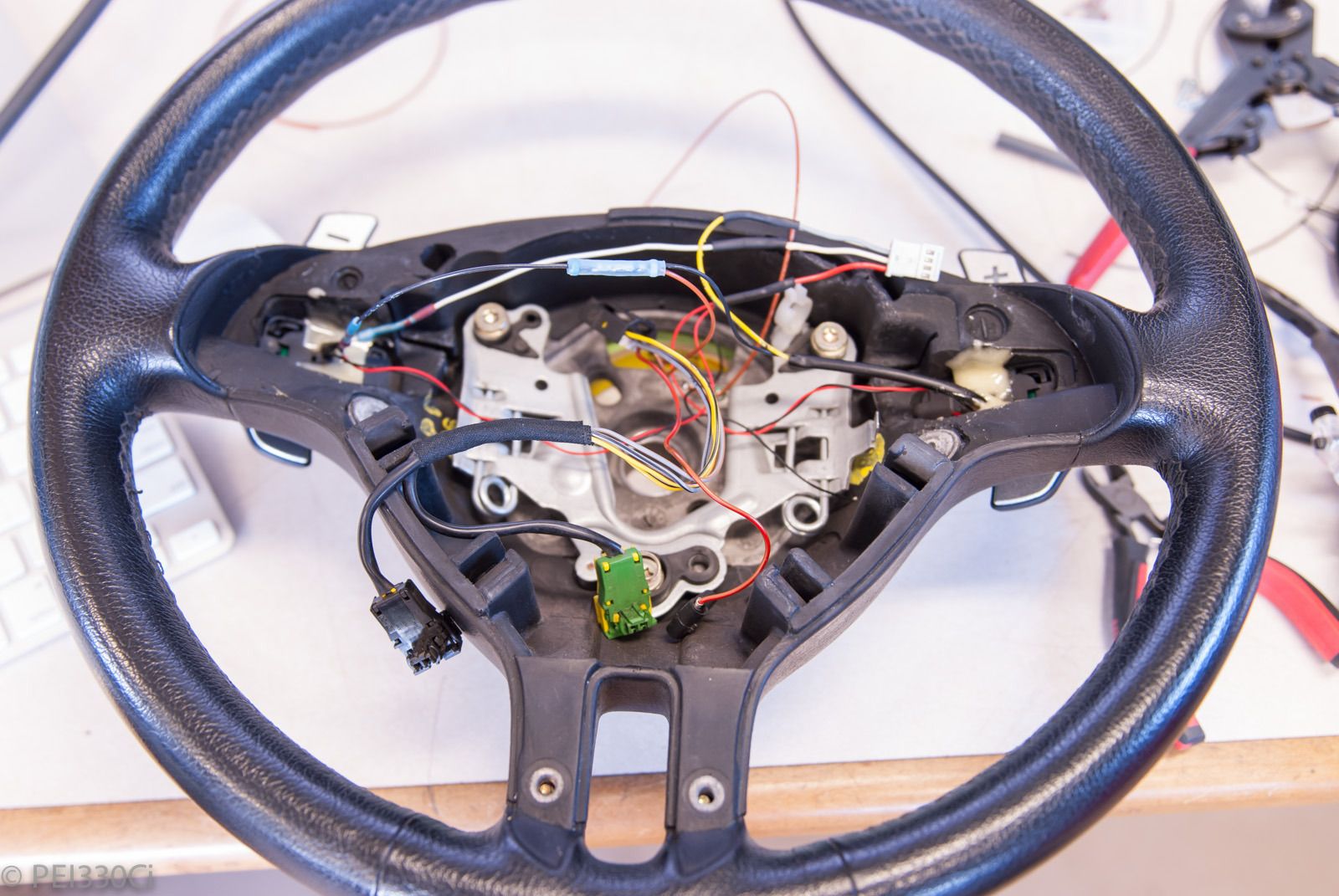
Sorting out the wiring inside the steering wheel:
I was looking to use a CAN switch input device, but decided at the last moment to ditch the OEM switch signals, and use the wire traces through the steering column for the paddle shifters.
Member
Adam do you have a picture of the slip ring? I have an E46 M3 wheel on my E34 and never bothered to try and get the slip ring to work hence none of my wiring connects. I have wiring provisioned to use the volume and down buttons for boost up and down, etc., but obviously can't connect any of it w/o knowing how the wiring ordinarily goes through the column.
ßMW///MµrÐêr§þðr
Those look to be RG_R's.
Do they still make them?
or did you "procure" them somewhere?
M54B30 Inside
No I don't have any pictures, but I do have a pin-out.
Are you using an E46 Volute spring?
Yes they are RG-Rs, I bought them with the car. (P.O. was selling a bunch of BBS stuff separately.)
They don't list RG-Rs in this offset anymore with a 5 X 120mm bolt pattern; my next set of wheels will likely be from HRE.
Member
Volute == clock/slip ring
No, but I can get one. I have no spring in place just the wheel attached.
Major Lazer
Adam, what is your strategy for ensuring 100% accuracy when building the harness?
I built my first harness a few years ago and made one mistake; I mis-pinned the Idle Air Control Valve which caused idle issues and took me a while to catch the error. I'm now building a second harness and have devised a system to ensure 100% accuracy but I'd like to hear your approach.
2003 M5 LSx l 6 Spd Manual l 4.10 LSD
Build Thread
The chassis must always be regarded as a means to an end and never as an end itself
 Posting Permissions


 Reply With Quote
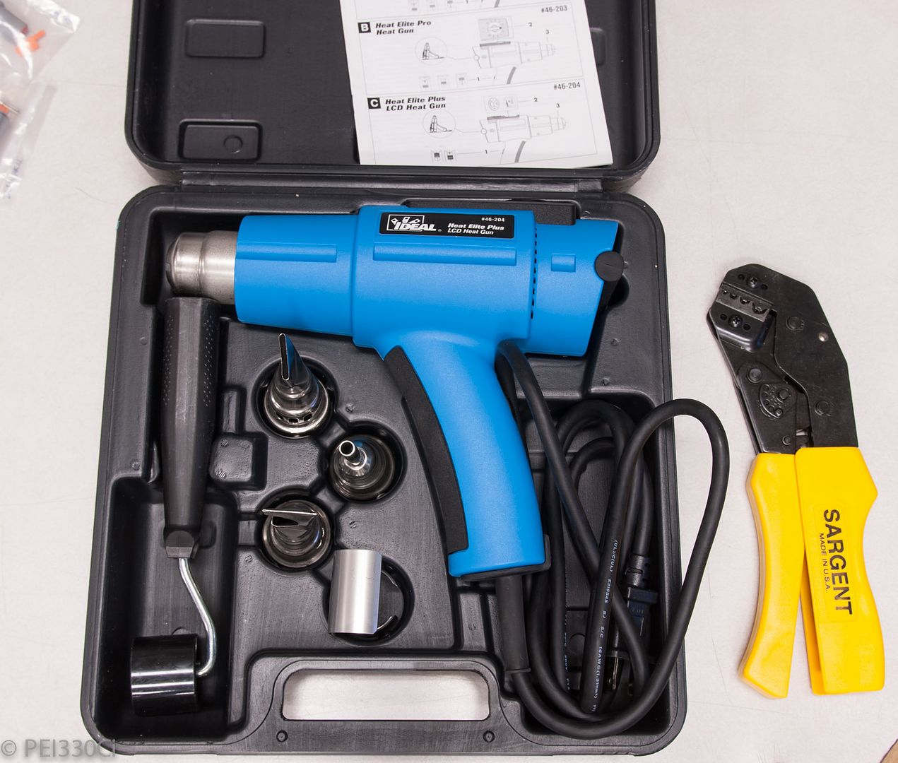


Bookmarks