
 M54B30 Inside
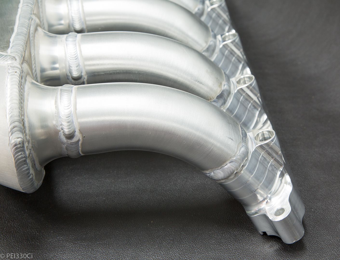
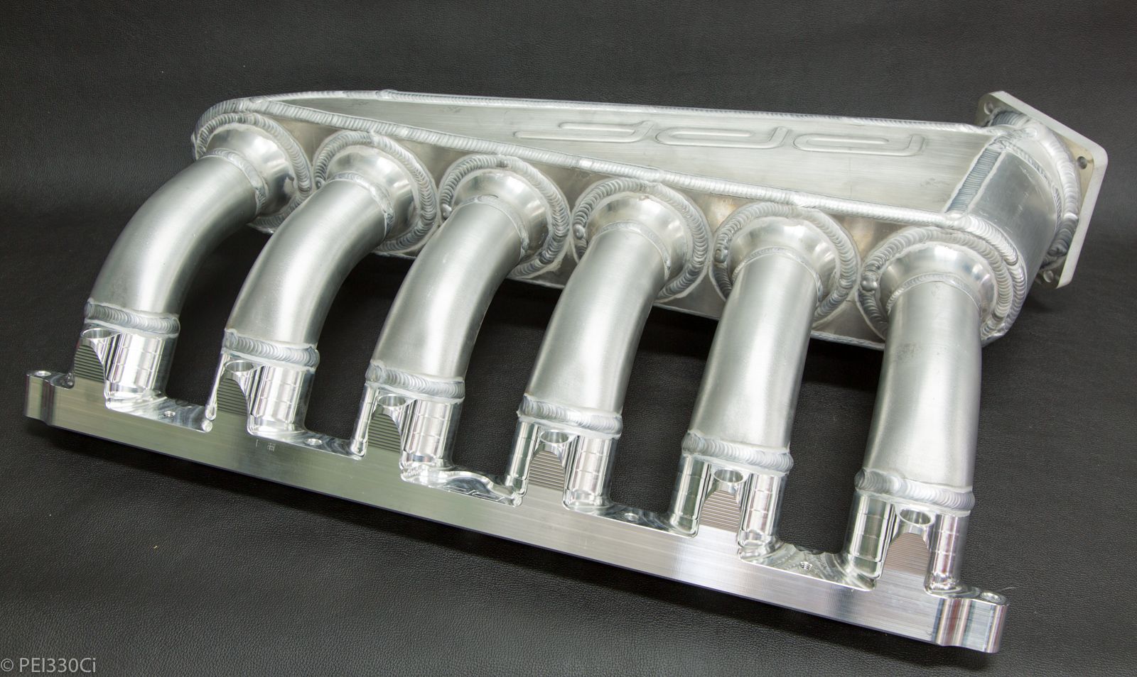
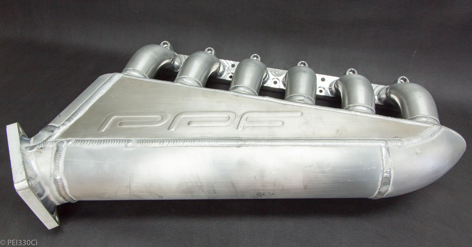
The currently unlisted M54 Intake manifold from PPF:
Cantry Member
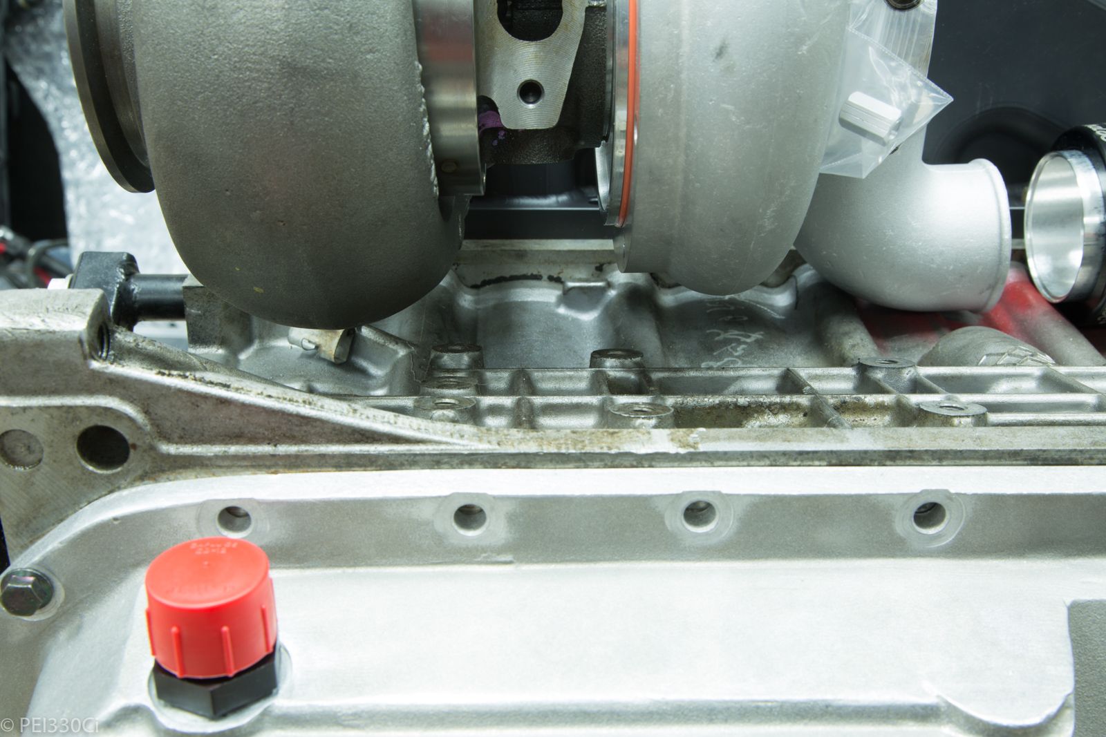
Isnt there an oil scraper that goes in the oil pan?
M54B30 Inside
Why would I need one?Originally Posted by chikinhed

It's not so much a scraper, as a slosh protector between the rotating crank and the oil foam in the wet sump pan.
With a dry sump, there's nothing there to slosh....
Member
That PPF intake is horrible
Member
I cant wait to see pictures of everything put together and some vids of the car. Your old setup was already great, this is going to be a crazy setup. I may have missed it but what driveshaft/diff/axle setup are you going to be running for this?
Lurker
BMW CCA Member
I know this is more than just your opinion. Please explain the logic behind your statement .
Member
Intake looks great Adam!
1000+RWHP, Lab22 Built Turbo S54 - BMW Half Mile Record Holder
M54B30 Inside
Thanks!
Paul Yaw and Shane T gave a big thumbs up to the injector angle.
M54B30 Inside
Axles - DSS
Diff - E46 M3 (210mm) built by Wanganstyle with custom Cusco centre section.
Driveshaft - Luxfab
Member
Whoa... I have some catching up to do on this insanity.
95 turbo 330ti. 01 maxpsi m3 e85. 01 m5. 01 m coupe. 03 AIM 996t e85. 06 x3 w/Meyers plow and winter daily. Prussian Motors is hiring!! prussianmotors.com/jobs
Current e39t LS Turbo swap: https://www.bimmerforums.com/forum/s...LS-e39-Touring
Member
Definitely way better injector angle than mine lol.
Last edited by Commanderwiggin; 06-18-2018 at 09:32 AM.
1000+RWHP, Lab22 Built Turbo S54 - BMW Half Mile Record Holder
Lead Disagreement Eng PE
I would probably install a brace somewhere on the plenum down to the engine block. Doesn't need to be much, but it'll make sure everything is happy.
6061-T6/T4 has a fatigue strength of ~10-12 ksi at 10e6-10e7 cycles, but a yield strength of ~30-40 ksi. It can be perfectly happy strength wise, but all the vibrations on an engine, and it being fairly stiff and unsupported on the end will cause it to have a really high natural frequency in bending, which will rack up some serious vibration cycles while the engine is running. Putting a brace on the far end will probably reduce fatigue stress by a factor of 4-8 without looking up any formulas.
M54B30 Inside
Thanks for the info.
The M54 Block has a spot on it for a support bracket on the OEM intake, I'll probably re-use that point.
M54B30 Inside
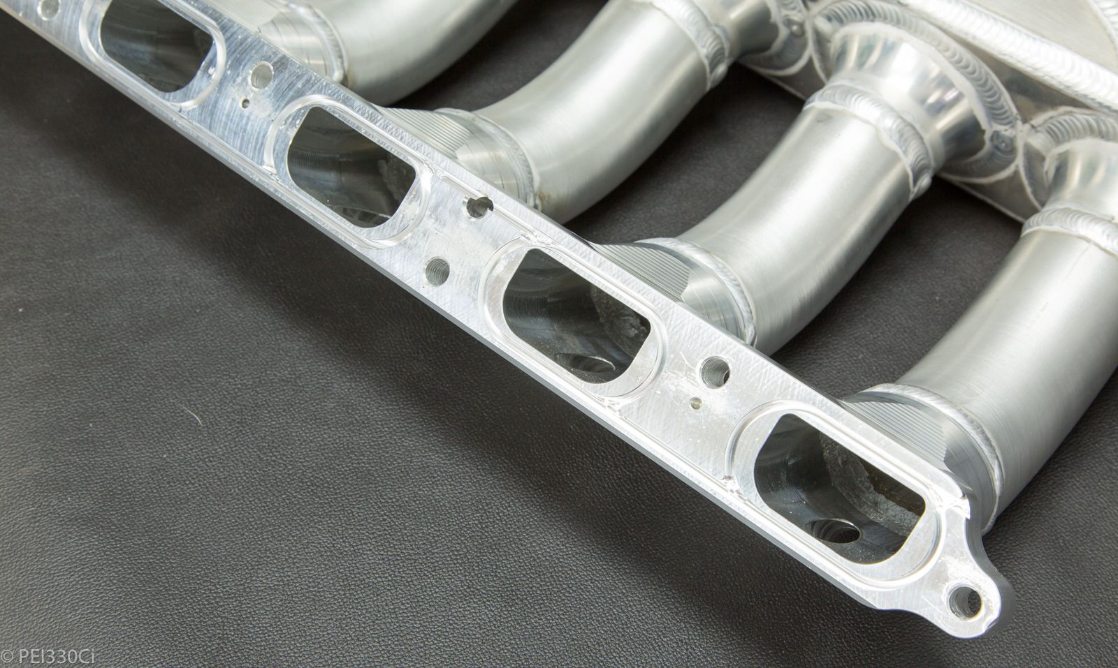
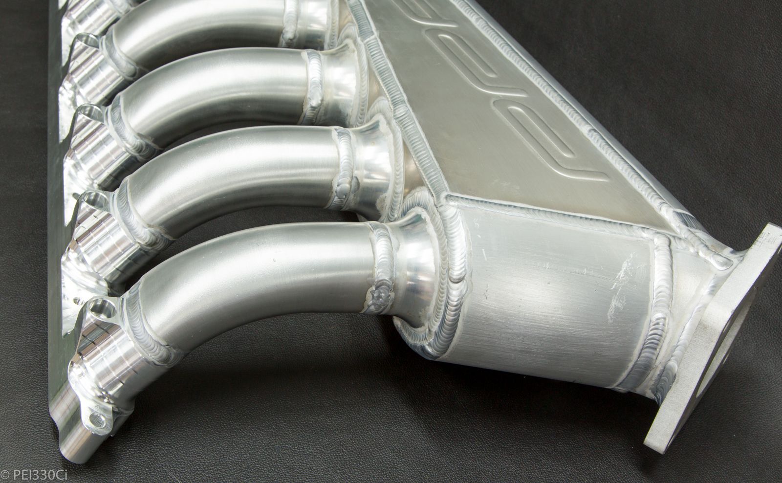
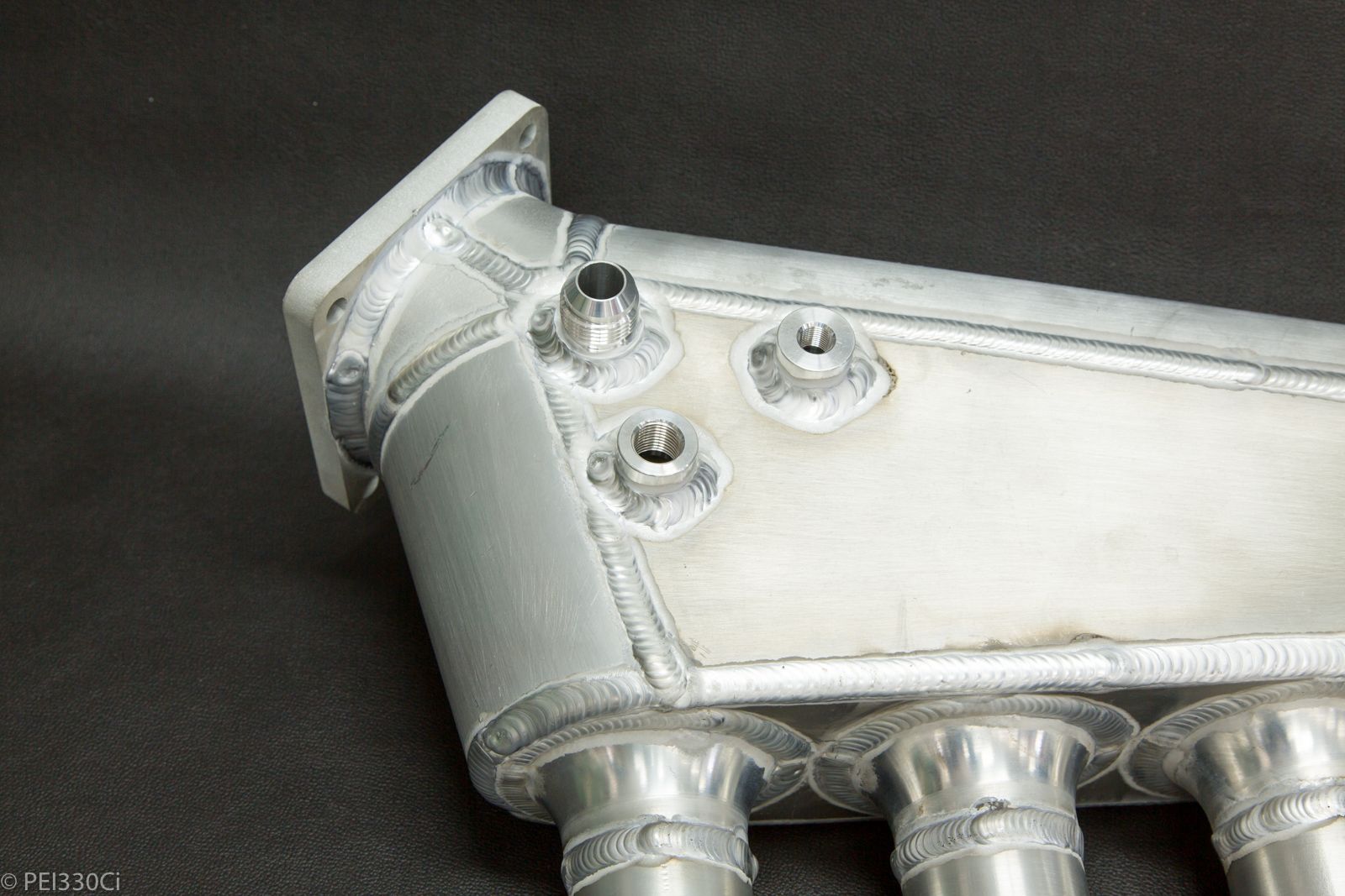
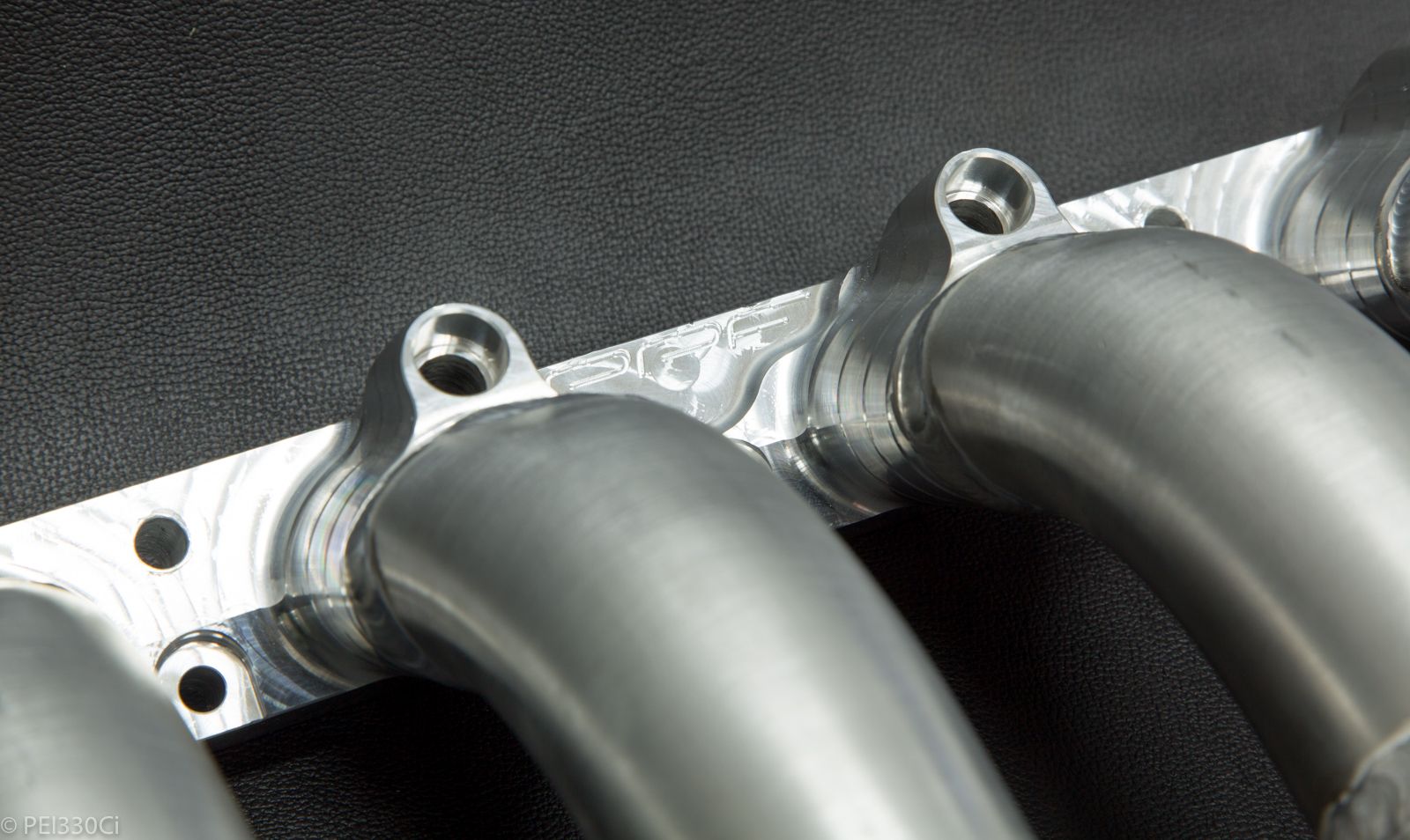
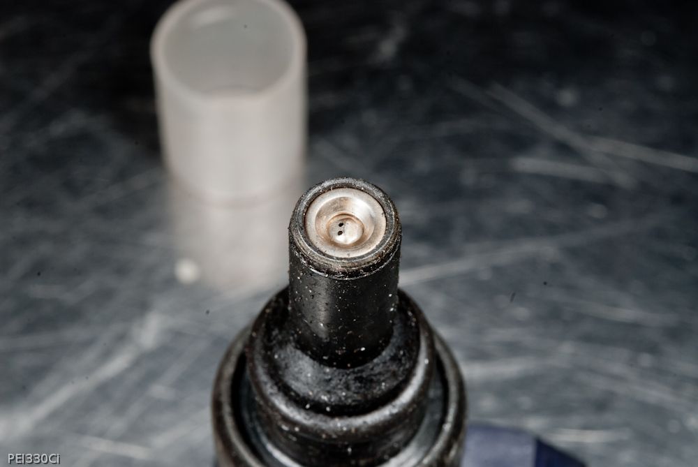
Detail shots of the injector angle:
M54B30 Inside
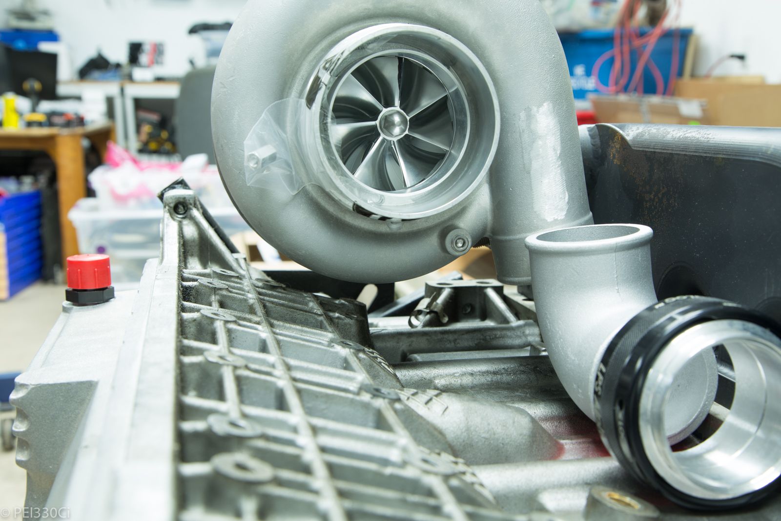
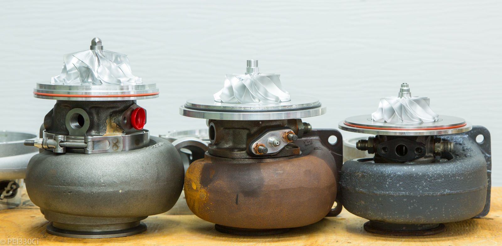
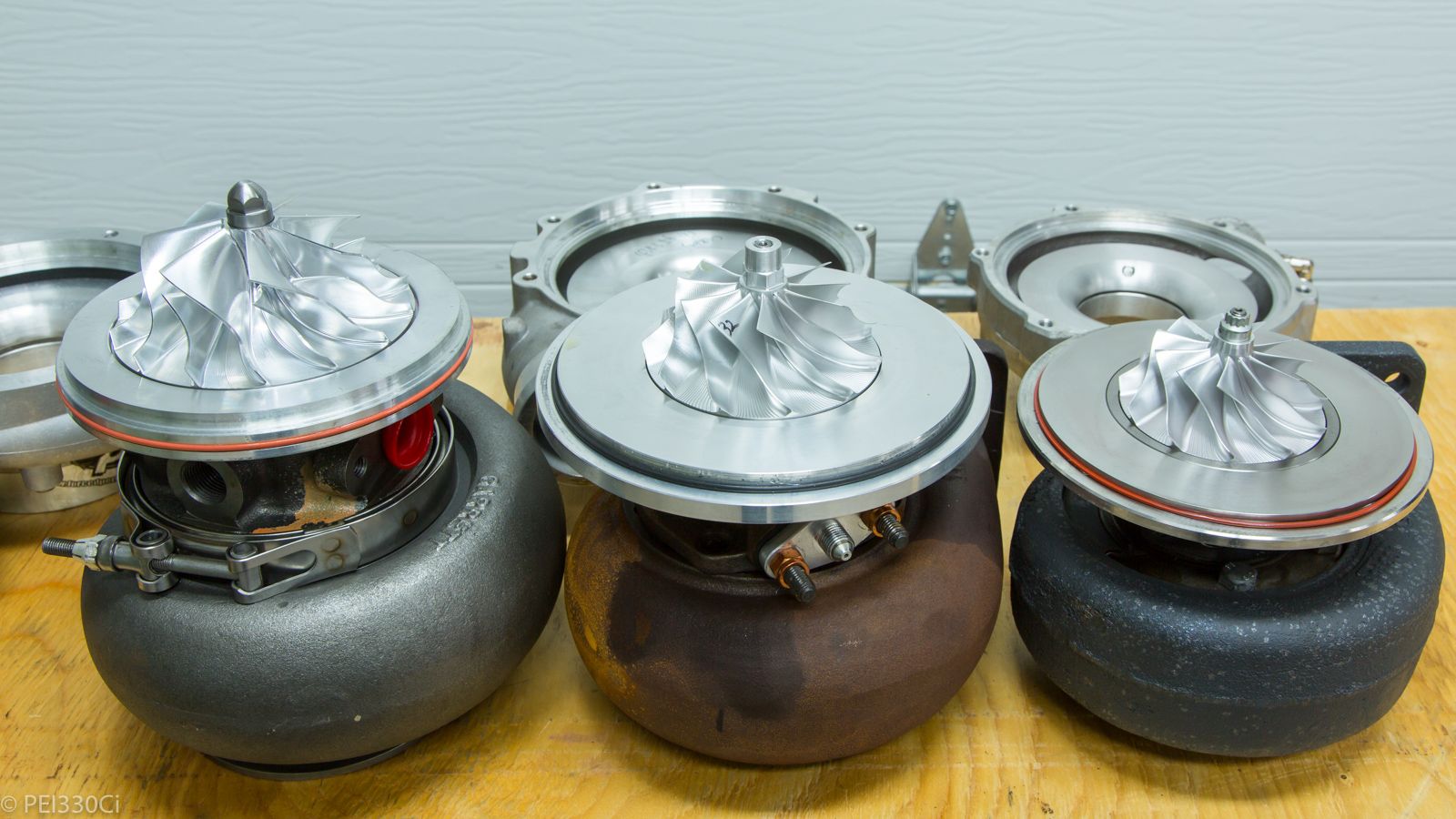
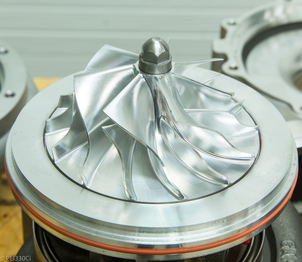
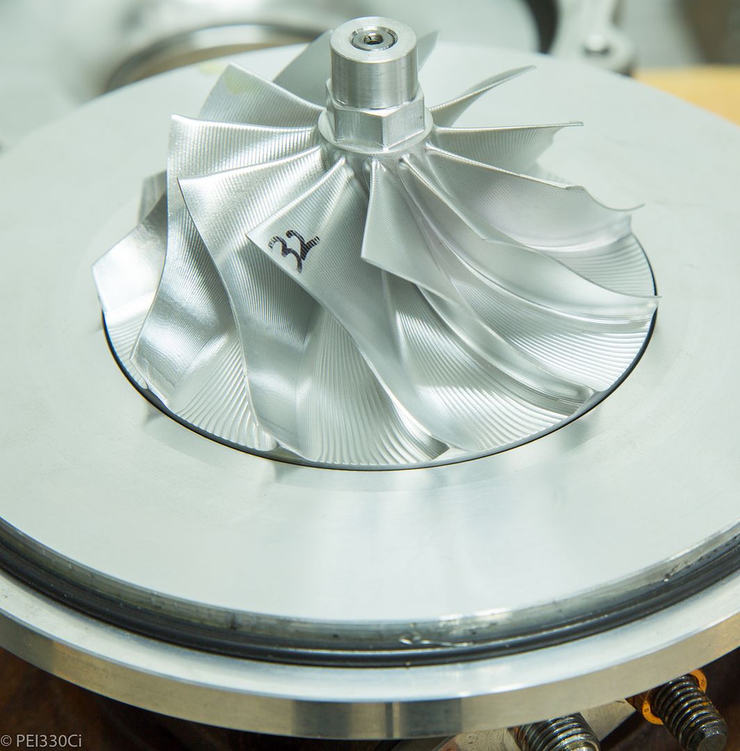
Turbos:
Garrett GTX3076R Compressor wheel:
Garrett GTX4088R Compressor wheel:
Forced Performance HTZ GT4205R Compressor wheel:
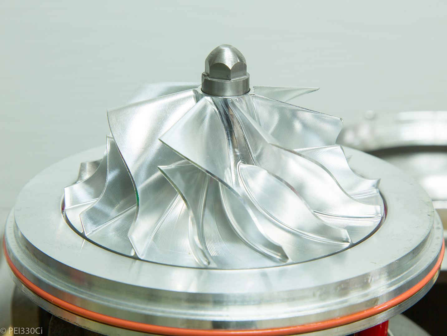
The difference in the finished machining between the Garrett and FP is quite stunning in person.
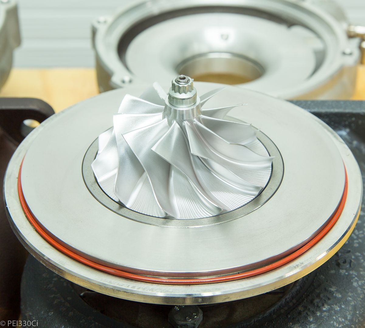
GTX40:
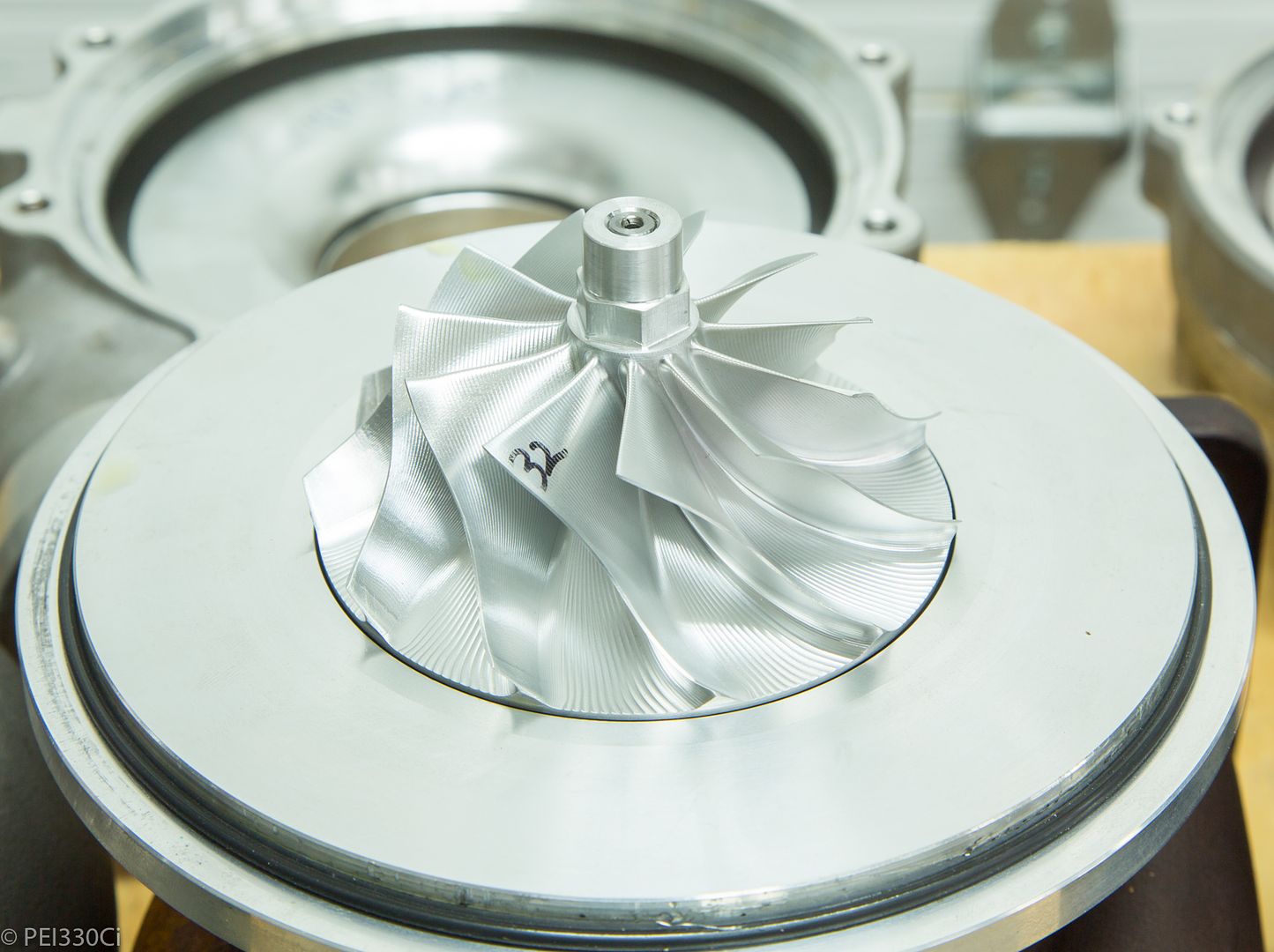
HTZ GT42:
- - - Updated - - -
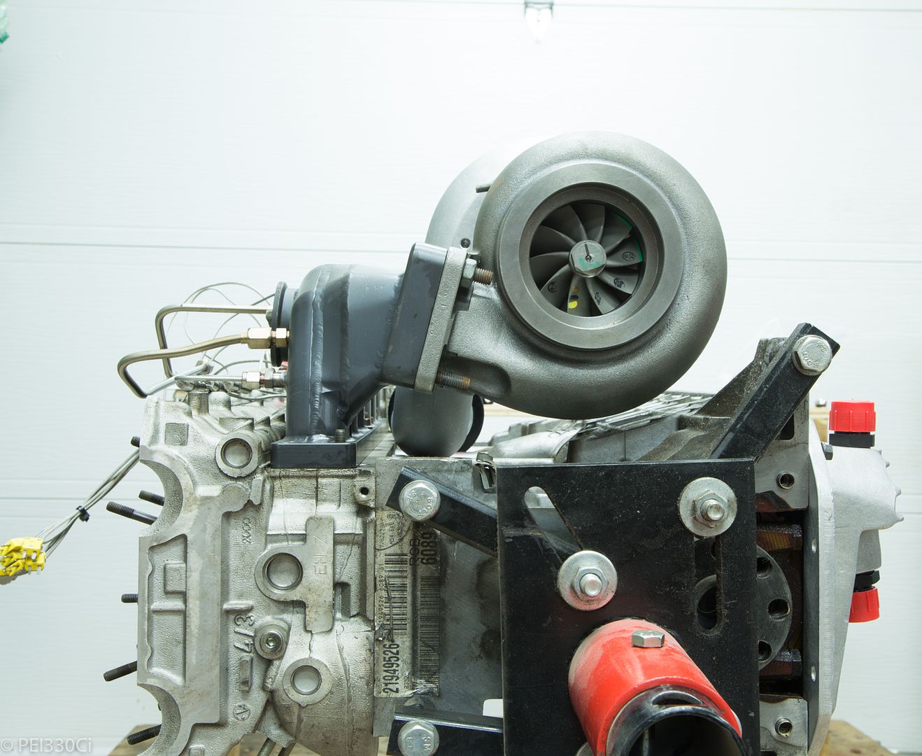
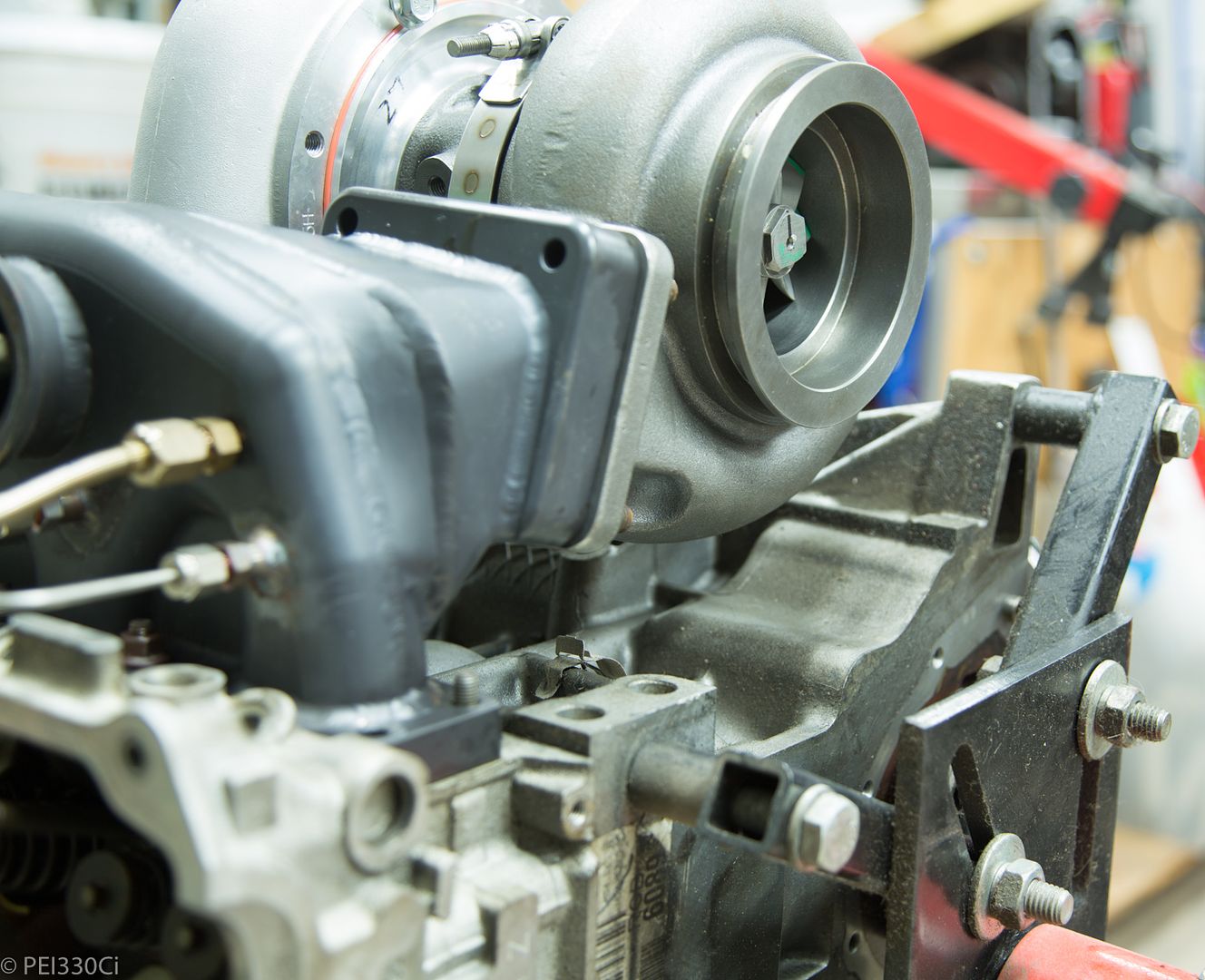
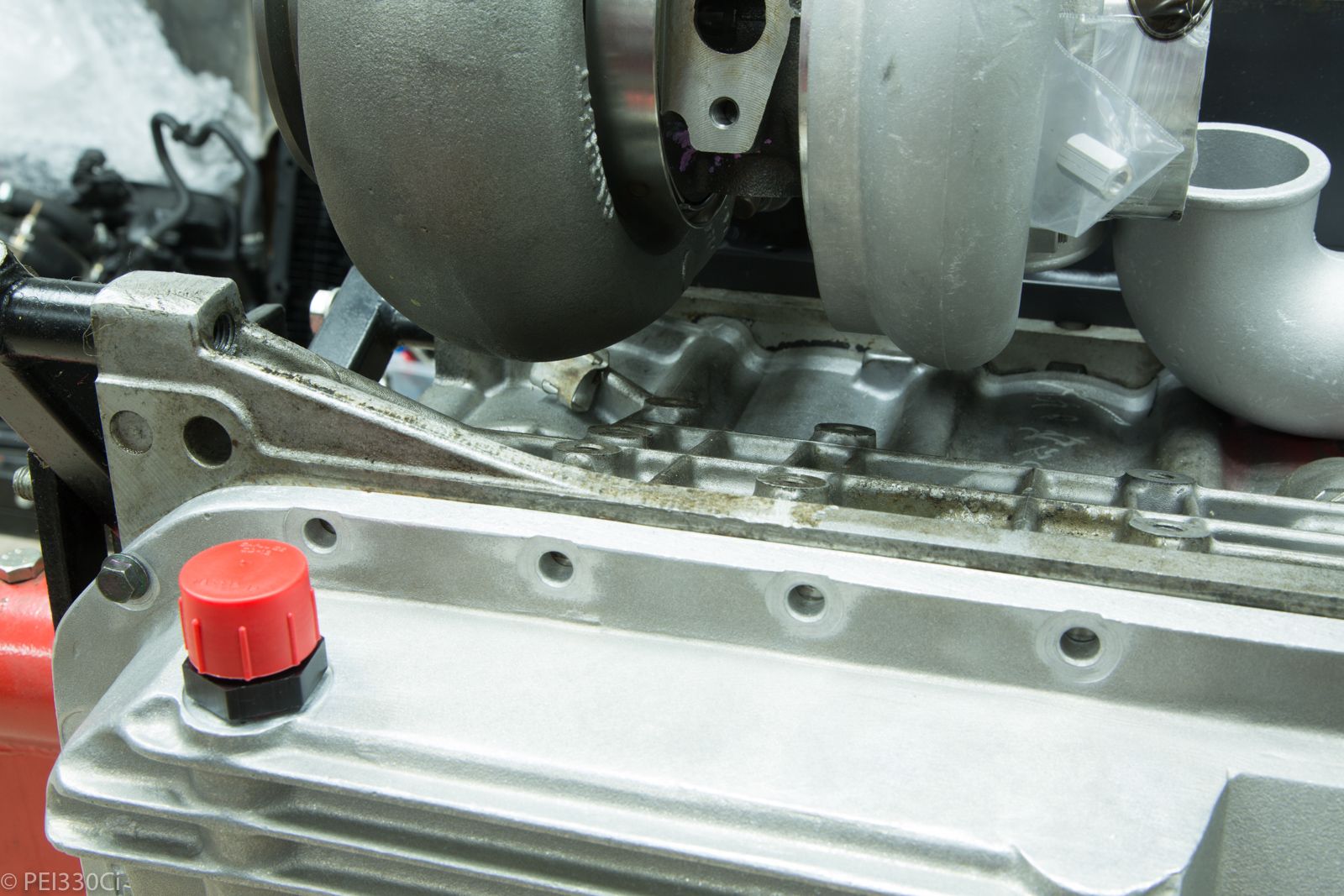
And yes, the HTZ GT4205R fits on the engine with the SS TS manifold:
Lead Disagreement Eng PE
Interesting that the Garrett has a much larger blade root fillet radius than the FP compressor. Obviously Garrett is trying to reduce peak stress there at the expense of some flow area, while FP has chosen to go really aggressive.
u owe my mule an apology
I'll bet it was more of a concession to cutter size and machine time.
86 325es, 2.8L m50, S476sxe, ProEFI 128 ecu, e85, solid rear axle, TH400 trans, 28x10.5w slicks, zip ties, popsicle sticks, tape
best time 9.06 @ 151.8 mph, best 60 foot 1.30
Lead Disagreement Eng PE
I've never seen a fillet radius selected solely to get a slight decrease in machine time. It has a very real impact on maximum stress on a part like this (blades loaded in bending).
I think it probably speaks to Garrett having a more conservative engineering approach, or even having people familiar with durability-limited turbomachinery stress analysis on staff.
Luchador
Thats what I always assumed it was. More of a mass production cutter choice.
Def, I would have thought the less finished blades (machine marks visible) would add more stress risers and be worse for long term robustness.
{Edit} Reread and then figured you were not talking about the blade itself but the fillet radius where the blade meets the back face. Here the FP has a much smaller radius which would definitely be worse for robustness doue to fatigue. Is this what you were talking about??
Adam, does the injector angle match OEM? Is the injector spray from the injectors you are using the same, or is the manifold made to match with the EV14 spray angle?
Last edited by wazzu70; 06-20-2018 at 03:13 PM.
Ring Master
Man I did a Wiggins in almost that same placement real close to some ribs on the block. I regretted that for the whole time I had the build. Hah. Next build I turned 90 down behind the air compressor and it was way better off.
Top notch stuff as usual man.
Sent from my iPhone using Tapatalk
1989 535i - sold
1999 M3 Tiag/Dove - sold
1998 M3 Turbo Arctic/black - current
2004 Built motor TiAg/Black - Sold
2008 E61 19T Turbo-Wagon - current
2011 E82 135i - S85 Swap - current
1998 M3 Cosmos S54 swapped Sedan - current
1998 Turbo: PTE6870 | 1.15 ar | Hp Cover, Custom Divided T4 bottom-mount, 3.5" SS exhaust, Dual Turbosmart Compgates, Turbosmart Raceport BOV, 3.5" Treadstone Intercooler, 3.5" Vibrant resonator and muffler, Arp 2k Headstuds | Arp 2k Main studs | 87mm Je pistons | Eagle rods | 9.2:1 static compression, Ces 87mm cutring, Custom solid rear subframe bushings, Akg 85d diff bushings, 4 clutch 3.15 diff, , Poly engine mounts, UUC trans mounts W/ enforcers, 22RPD OBD2 Stock ECU id1700 E85 tune, 22RPD Big power Transmission swap w/ GS6-53
Lead Disagreement Eng PE
Yes, I'm talking about the blade root radius. It will have a higher stress, and have a cyclical component on top of it, which is probably going to dominate the part's failure mode (high cycle fatigue failure).
The machined tool path ridges aren't good for fatigue, but the higher stressed parts like the blade root have much better surface finish on both parts, and that's what you really want to tightly control. The blade hub/back face doesn't really matter as it's so low stress.
u owe my mule an apology
Note to self, replace compressor wheel due to fatigue in 400,000 miles. Put it next to the oil change sticker.
86 325es, 2.8L m50, S476sxe, ProEFI 128 ecu, e85, solid rear axle, TH400 trans, 28x10.5w slicks, zip ties, popsicle sticks, tape
best time 9.06 @ 151.8 mph, best 60 foot 1.30
M54B30 Inside
Complex answer.
The OEM M54B30 injector bungs are angled, but still pointed at the port floor. This was done due to space constraints with the injector electrical connectors, and the CCV capture system. BMW had injectors made with a 25 degree spray angle to point the fuel directly at the back of the intake valves:
When you put an aftermarket injector into the M54B30 intake manifold, it sprays fuel at the port floor, not at the back of the intake valves. This makes tuning part throttle tip-in, and even idle very difficult. (I've had a lot of difficulty getting good response under light load) In searching for help on the fuel film tuning, I initially found that pointing the injectors at the valves was a common fix, but that it had unexpected additional benefits. It helped with fuel mixture preparation so much, that it helped improved the mass fraction burn % before 20 deg ATDC which improves both power output and burn stability. (Smoother dyno plots) If you are close to the edge for cylinder knock, having a more consistent burn speed across all combustion events means you can be safer with timing.
The PPF M54 intake manifold points the injector directly down the port at the inlet valves. So the fuel spray axis is similar to OEM, but how it achieves this is different....
This is my first time trying something like this. What was it that bothered you about putting a coupler in that location? Heat?
Until I'm able to put the engine back in the car, I won't be doing anything further past the 90 degree elbow on the compressor outlet. I still have to figure out the engine mount, the turbo inlet, and there is a dry sump pump and whole host of large hoses that need to fit in there as well.
I tend to change parts out before they get anywhere near the end of their fatigue life....I'm not too worried about it.
Ring Master
There was just zero access there between the inlet pipe or filter, compressor, and subframe. The coupler ended up being non-remove-able. It was nice as I could flex or rotate the pipe but it was basically permanent.
Oh and at some point I clocked the turbo a bit and the coupler was touching the block and was even more permanent
Sent from my iPhone using Tapatalk
1989 535i - sold
1999 M3 Tiag/Dove - sold
1998 M3 Turbo Arctic/black - current
2004 Built motor TiAg/Black - Sold
2008 E61 19T Turbo-Wagon - current
2011 E82 135i - S85 Swap - current
1998 M3 Cosmos S54 swapped Sedan - current
1998 Turbo: PTE6870 | 1.15 ar | Hp Cover, Custom Divided T4 bottom-mount, 3.5" SS exhaust, Dual Turbosmart Compgates, Turbosmart Raceport BOV, 3.5" Treadstone Intercooler, 3.5" Vibrant resonator and muffler, Arp 2k Headstuds | Arp 2k Main studs | 87mm Je pistons | Eagle rods | 9.2:1 static compression, Ces 87mm cutring, Custom solid rear subframe bushings, Akg 85d diff bushings, 4 clutch 3.15 diff, , Poly engine mounts, UUC trans mounts W/ enforcers, 22RPD OBD2 Stock ECU id1700 E85 tune, 22RPD Big power Transmission swap w/ GS6-53
Lead Disagreement Eng PE
This can happen much MUCH quicker than that. If theres a sharp bend on the inlet pipe right in front of the compressor, the total pressure distortion across the compressor face can make each blade flex a small amount during each revolution. At 150k+ RPM, you can go well into the billions of cycles in a relatively short time. Aluminum also has no endurance limit (plateau of fatigue strength), so it WILL eventually fail when subjected to cyclical loading.
 Posting Permissions


 Reply With Quote

Bookmarks