
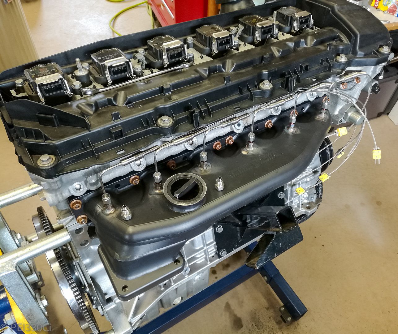
 M54B30 Inside
I had considered doing 2 tank systems.....but decided in the end it was too complicated for my application.Originally Posted by hsvturbo

M54B30 Inside
Here we go again:
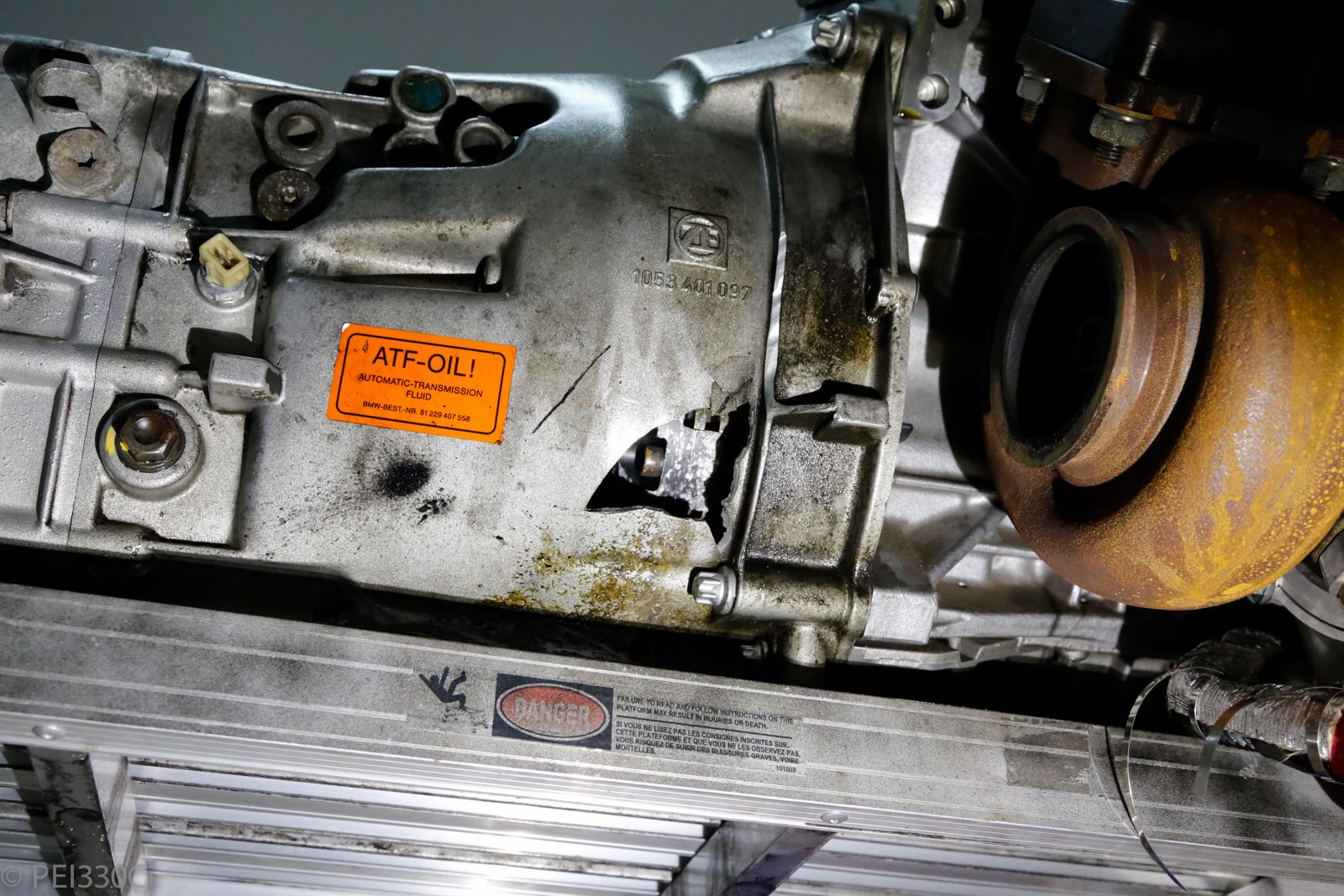
Had a problem with the slave cylinder that caused some damage:
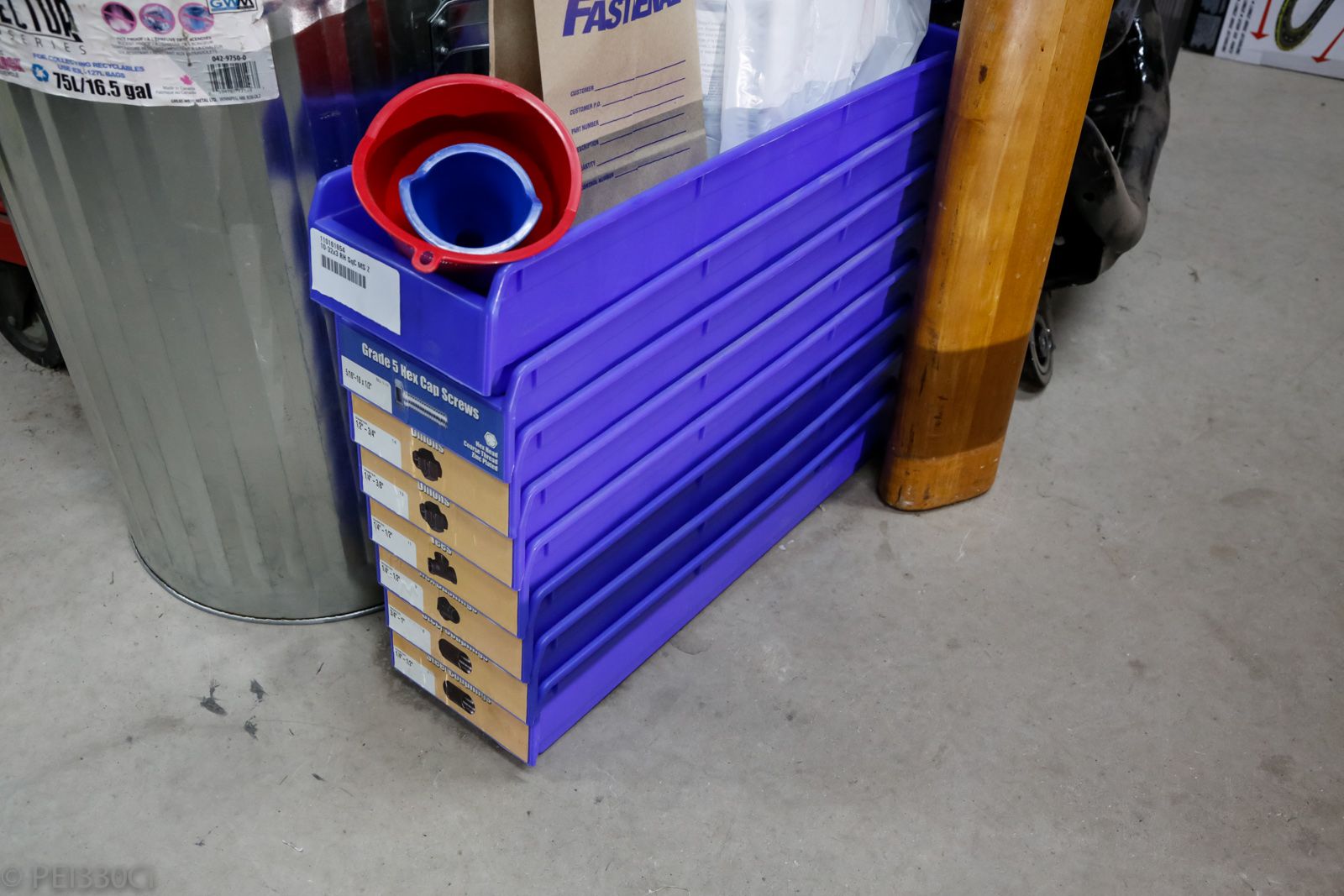
My local Fastenal was changing out all of it's bins, and was selling the old ones for cheap:
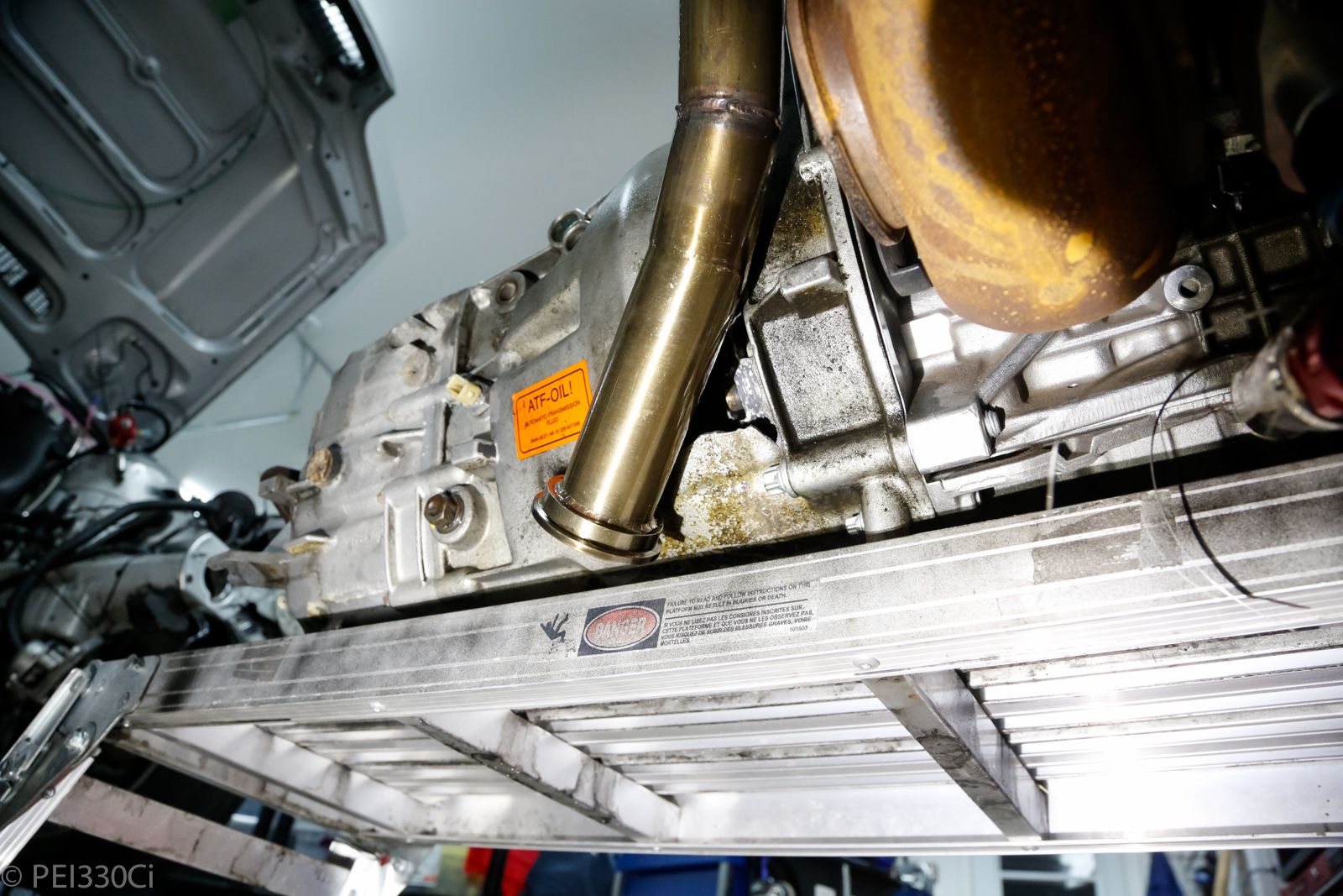
The exhaust studs weren't long enough to allow full engagement of the nuts with the Steed Speed. I thought partial engagement (75%) was enough....but it seems it wasn't:
I'm going to be replacing the 39mm exhaust studs with 55mm studs.
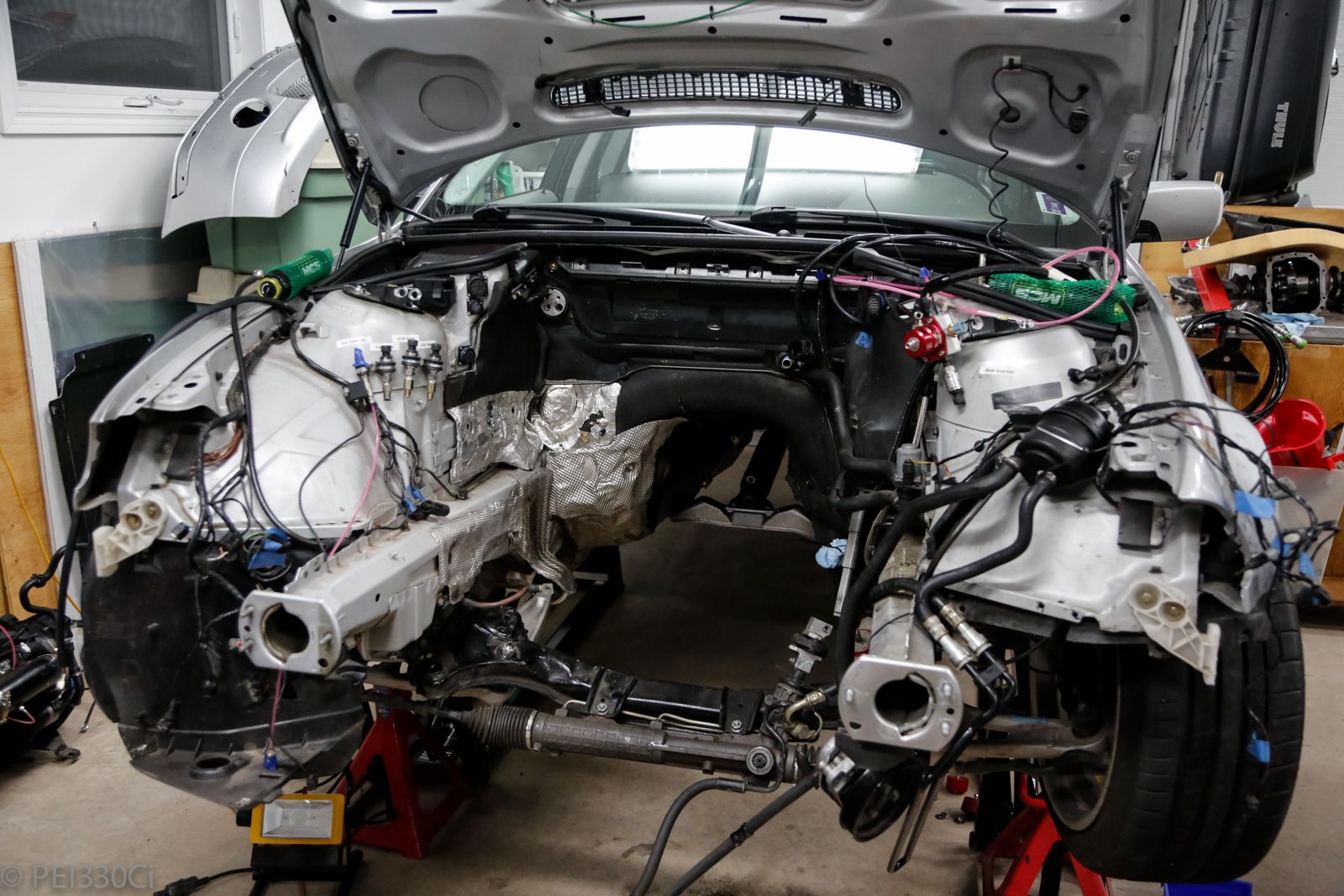
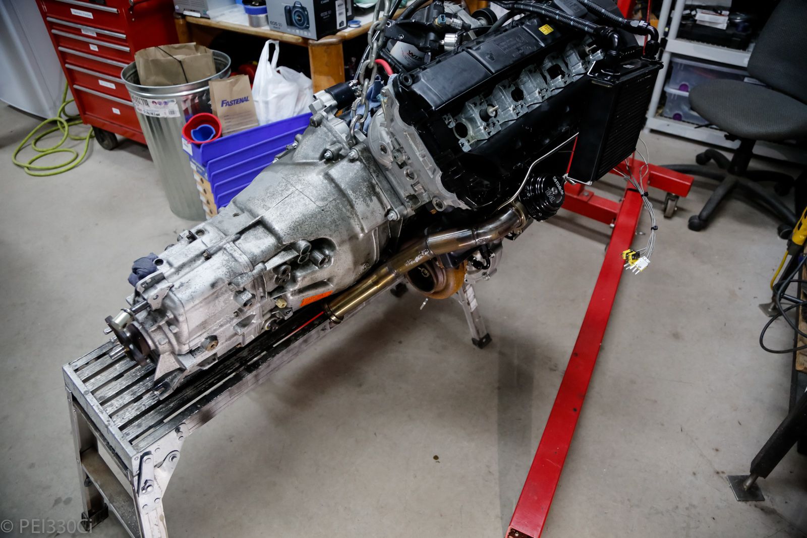
M54B30 Inside
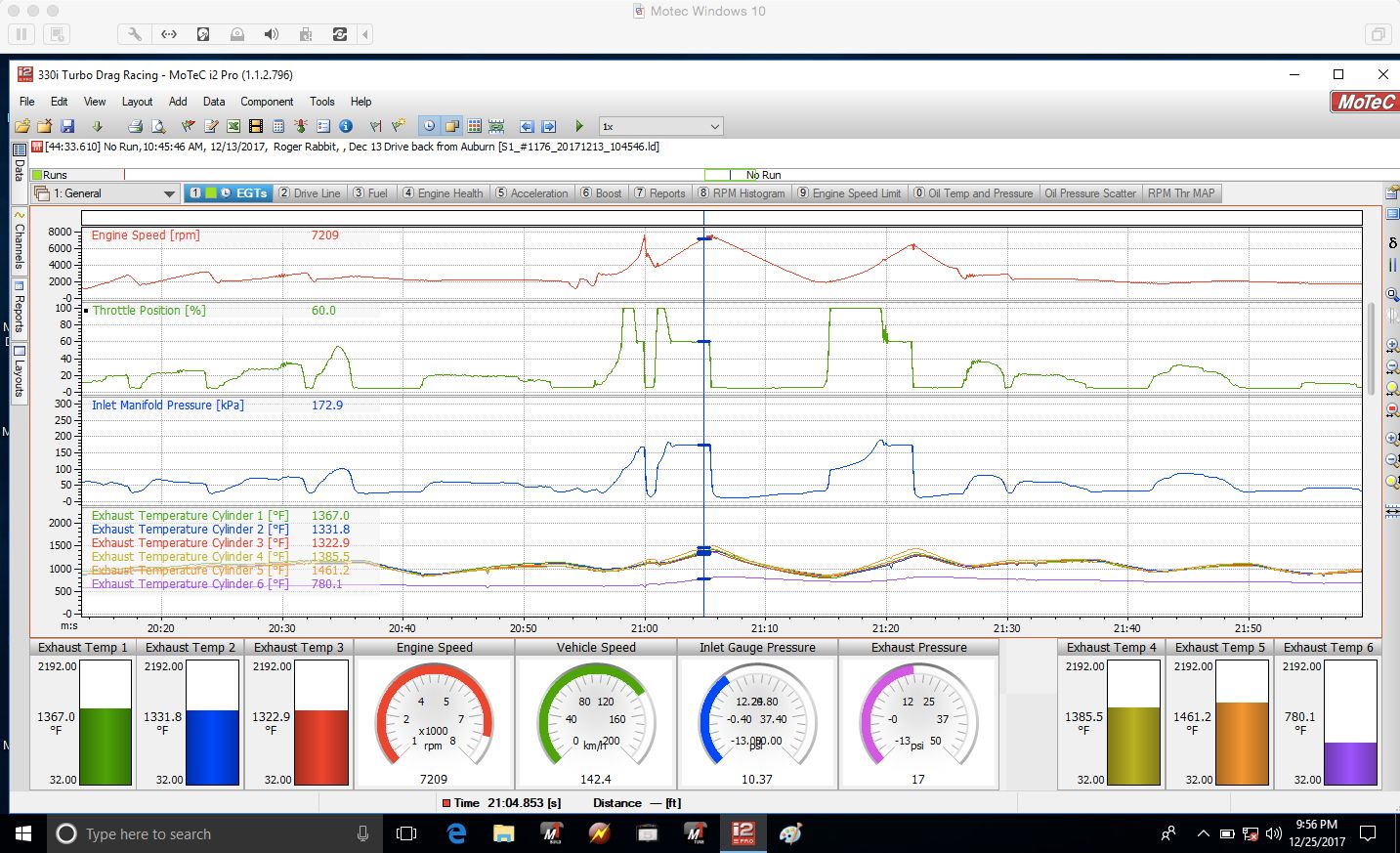
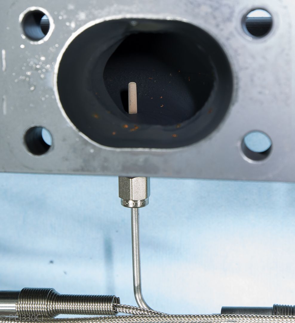
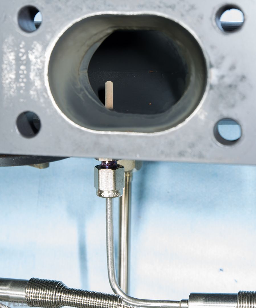
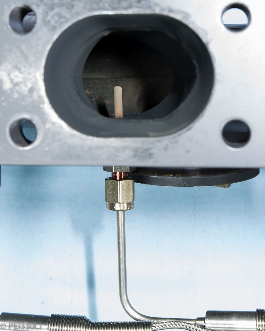
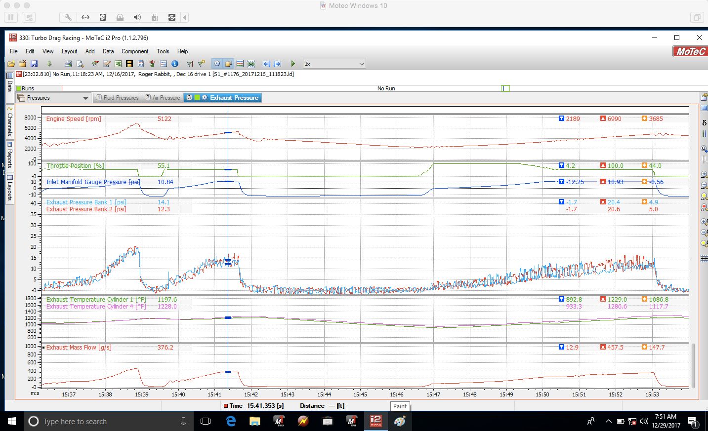
After changing out to a second new EGT sensor in cylinder #6, this was what I was seeing under load:
So I decided to take the Steed Speed exhaust manifold off with the EGT sensors still installed to investigate further...
Lead Disagreement Eng PE
Compression test done recently?
M54B30 Inside
All cylinders:
Cylinder 1:
Cylinder 2:
Cylinder 3:
Cylinder 4:
Cylinder 5:
Cylinder 6:
u owe my mule an apology
Awol
86 325es, 2.8L m50, S476sxe, ProEFI 128 ecu, e85, solid rear axle, TH400 trans, 28x10.5w slicks, zip ties, popsicle sticks, tape
best time 9.06 @ 151.8 mph, best 60 foot 1.30
M54B30 Inside
Well it's there....but keeping it's head in the bunker.
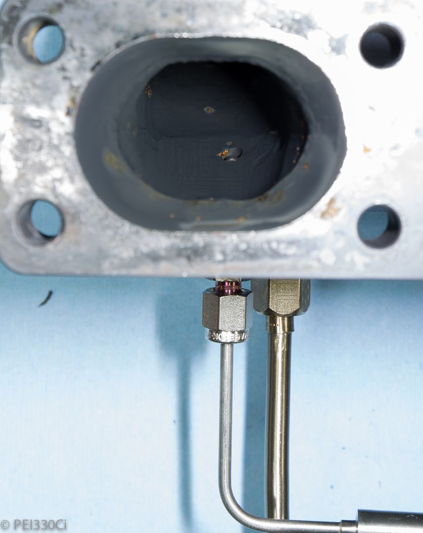
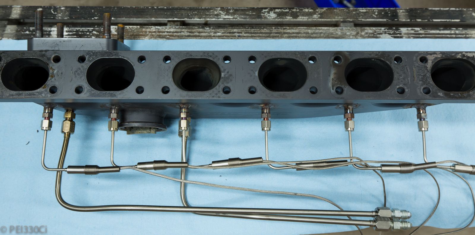
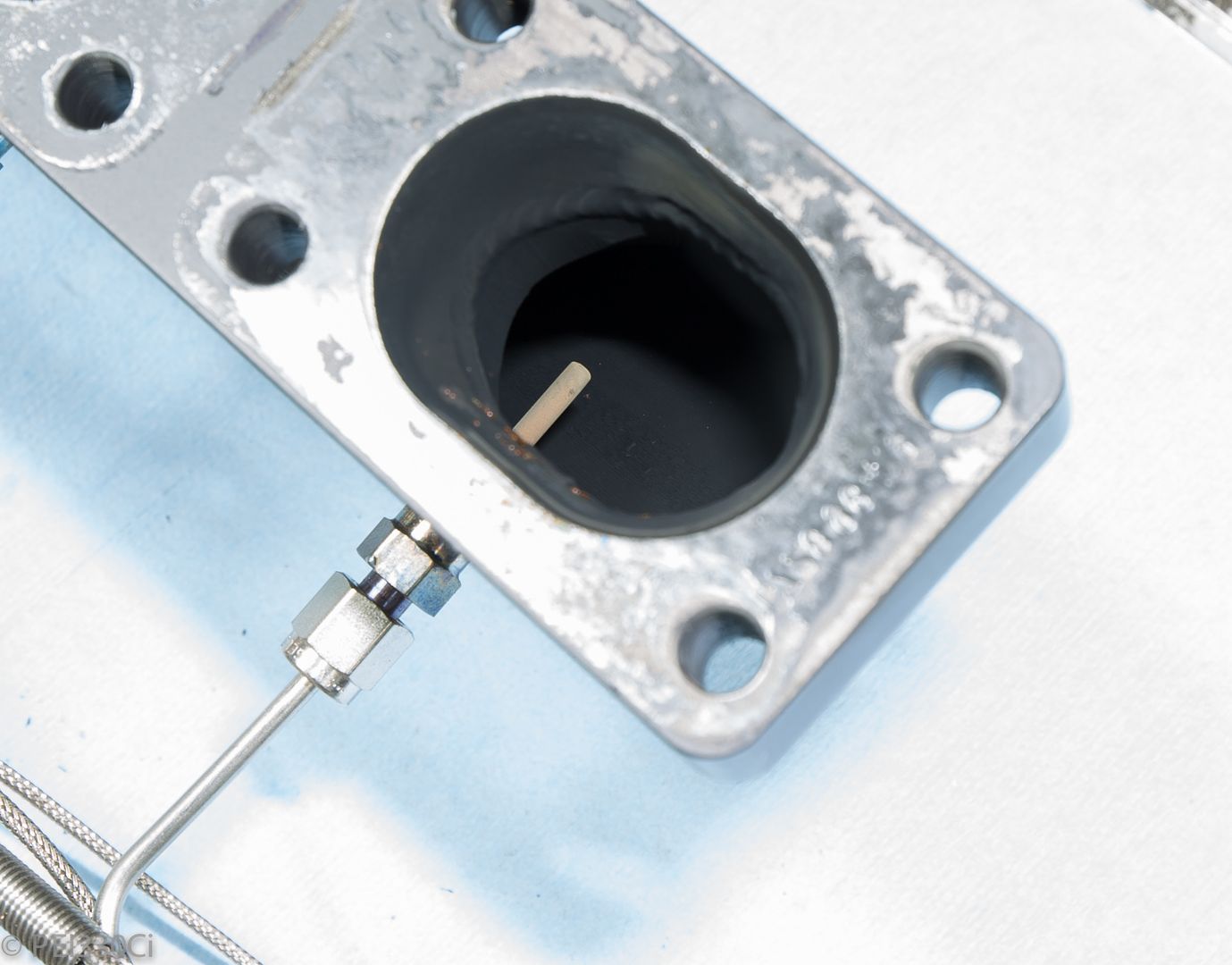
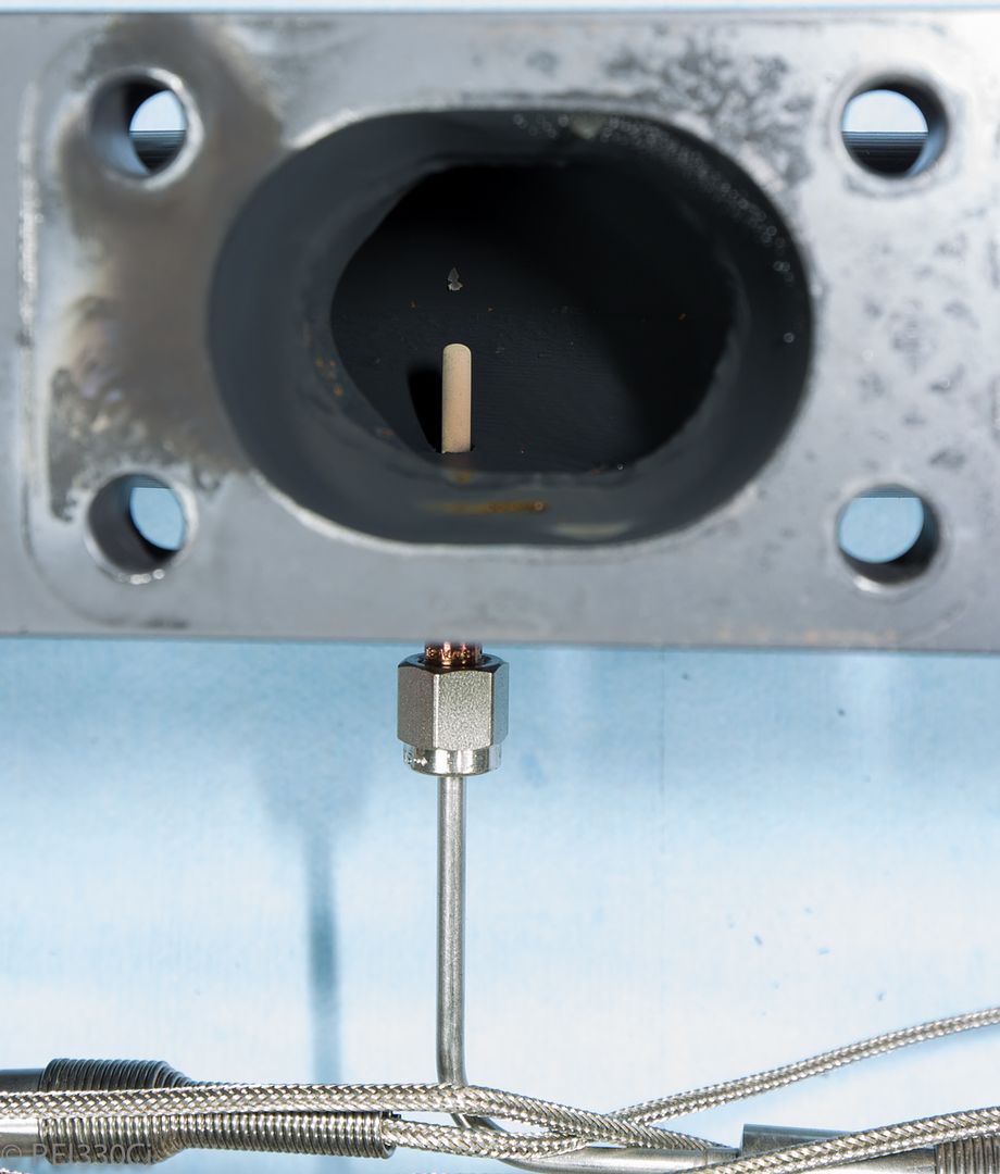
I was originally thinking I was going to set the tip height based on the port floor distance....but then it occurred to me that the total exposed length of the sensor in each cylinder might be different. (Resulting in differing exposed surface area to exhaust gas) Now I think I'm going to set the sensor tip in cylinder #6 to be 1/2 way into the port, and then match the protruded length on the other 5 sensors.
Member
You work fast! Keep up the progress on the revision and I love the detailed pics!
1000+RWHP, Lab22 Built Turbo S54 - BMW Half Mile Record Holder
M54B30 Inside
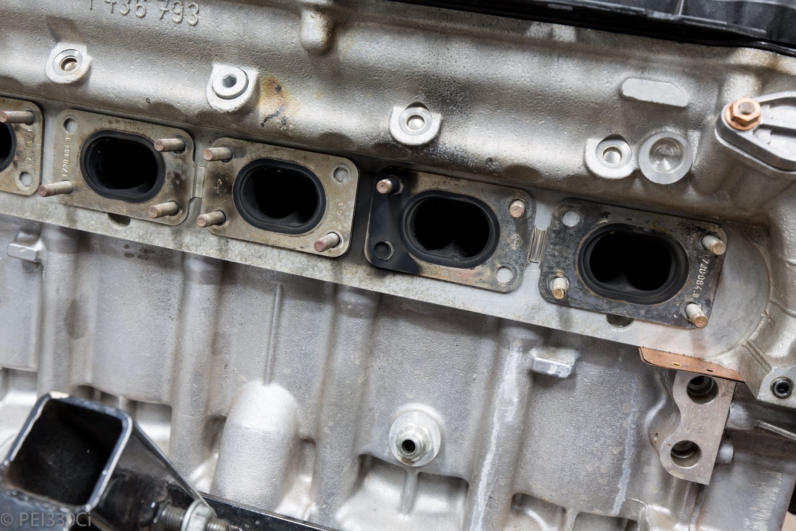
I did a leak down test.
Cylinder #1 = 22%
Cylinder #2 = 10%
Cylinder #3 = 8%
Cylinder #4 = 4%
Cylinder #5 - Could do because I dropped a washer on top of the spark plug and can't get it out. (Yet!)
Cylinder #6 = 20%
On cylinder #1, most of the leakage appears to be on the exhaust side, with a little bit of leakage on the inlet port.
On cylinder #6, the leakage is mostly on the exhaust port
Cylinders #2 - #4 is past the piston.
* Note, this was all done with the piston for each cylinder confirmed at TDC with the valves closed. The engine was cold....and had not been run in about a week.
Cylinder #1 and 6 I damaged the valves by running lean in 2016, and had to replace them. I lapped the new valves to the seats, but I really needed to cut the valve seats again....so the result above doesn't surprise me. I also noticed that some valves had more radial play than you would want.
The plan for the head now is to replace all of the valve guides and seals, and have all the seats re-cut. It will also get all new lifters in anticipation of running over 8k RPM.
M54B30 Inside
I'm determined to address the boost creep directly by addressing WG flow.
Changing the throttle position was a band aid, and while it worked to a degree, it caused some knock-on effects that I don't think are good. (Affecting load tables, stress on the DBW system, and higher exhaust back-pressure)
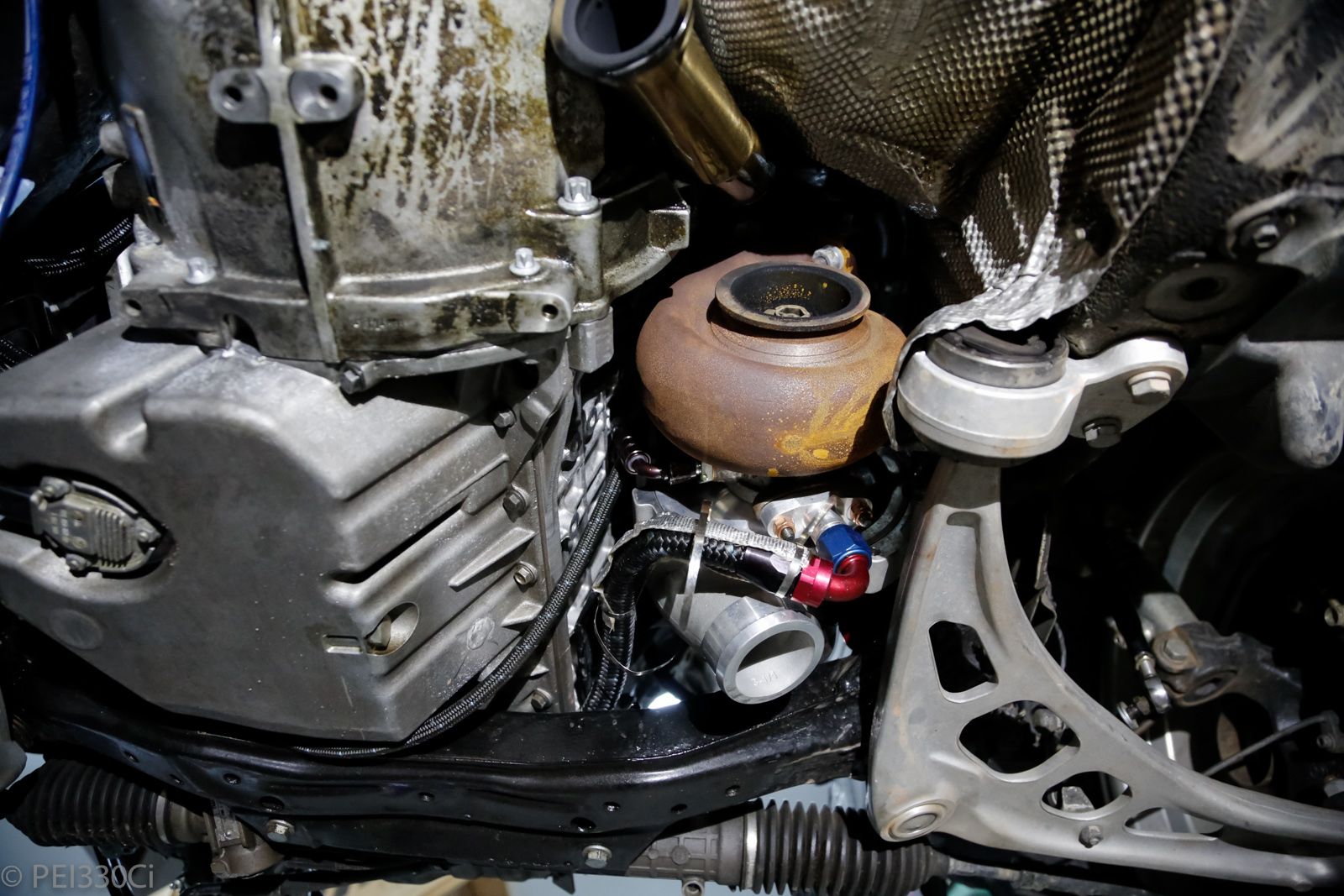
Additional WG flow as needed either from the SS TS manifold, or by attaching WG directly to the turbine housing.
There is space to place a single WG on the bottom of the turbine housing:
But....I'm reluctant to do it.
#1 - I'm not confident of a local welder pulling this off.
#2 - There is quite a bit of fabrication work to get a divider built into the WG to keep the system "twin scroll"
#3 - Putting a big hole on the exhaust flow following a decreasing radius manifold is going to cause turbulence....both with the WG open or closed.
This lead me to ask what factors influence WG flow? The main ones in this case are the flow area, and the angle of approach. Using the MVR on the turbine housing would maintain the flow area, but improve the angle of approach. What if the improved angle was still hindered by the flow area? What if I simply put a bigger WG on the SS TS exhaust manifold?
So I took some measurements:
Tial MVR
ID = 40mm
Flow Area = 1257 mm2
Divider Thickness = 6.9 mm
Divider Length = 40 mm
Divider Area = 276 mm2
Actual Flow Area = 981 mm2
Tial V60
ID = 63.5mm
Flow Area = 3167 mm2
Divider Thickness = 6.9 mm
Divider Length = 63.5 mm
Divider Area = 438 mm2
Actual Flow Area = 2729 mm2
So the actual flow area of the MVR is about 36% of what the V60 would be if installed by the same method.
LICENSE SUSPENDED
Hear me out on this...... This was a real quick stupid idea I had.
I'm not sure about your Garrett, but my precision housing has one of the split ports bigger than the other. What if we were to ONLY to drill out one of the sides of the housing and put a small WG. Instead of trying to split a WG port which would be a bitch. Keep the MVR up top and then put a small WG on only 1/2 the housing to direct some flow out. This just maybe enough ? I'm just not sure which side is better to tap ? This was my quick thought. Then I said screw it and just put in pop off valves and run the car at 25# all the time. I can say John heavily ported the WG port on the manifold and it helped a little. But still crept a lot.
Sent from my E6782 using Tapatalk
Last edited by Butters Stoch; 12-28-2017 at 10:21 PM.
1996 332IS
Built 3.2
CES/Steed TS Precision 6466, spraying a "$π!℅" load of meth.
Technique Tuning 80# tune.
1/4 mile 10.84 @ 136.72
Your 1 and only stop for all your BMW performance needs
WWW.CESMOTORSPORT.COM
u owe my mule an apology
Sounds like a good way to have 30 lbs of drive pressure on 3 cylinders and 15 on the other.
86 325es, 2.8L m50, S476sxe, ProEFI 128 ecu, e85, solid rear axle, TH400 trans, 28x10.5w slicks, zip ties, popsicle sticks, tape
best time 9.06 @ 151.8 mph, best 60 foot 1.30
LICENSE SUSPENDED
Wouldn't it equal out through the top gate ? If one bank has more pressure, it would work its way out at the top gate ? Sure there might be a difference, but surely not double.
Sent from my E6782 using Tapatalk
1996 332IS
Built 3.2
CES/Steed TS Precision 6466, spraying a "$π!℅" load of meth.
Technique Tuning 80# tune.
1/4 mile 10.84 @ 136.72
Your 1 and only stop for all your BMW performance needs
WWW.CESMOTORSPORT.COM
Member
The JGS 50 WG looks like it would fit the 44mm flange on the TS Steed but flow much more. It is not compact so you need clearance to the car body. This would be good to try if the engine was installed. With it out, I’d try modding the mani for a 60mm WG. Modding the twinscroll housing could be challenging. You could first build a divided pipe for the outlet and then trim it to fit perfectly and then cut the housing to fit the pipe.
M54B30 Inside
In theory, we already have a biased situation right now:
The WG port on Bank 1 is ahead of Cylinders #1 - #3.
The WG port on Bank 2 is ahead of Cylinder #4, but Cylinder 5 is slightly ahead of the WG port. Cylinder #6 can't "see" the WG port at all. So from an exposure perspective, we could assume the following:
Cylinder #1 = 100%
Cylinder #2 = 100%
Cylinder #3 = 100%
Cylinder #4 = 100%
Cylinder #5 = 50%
Cylinder #6 = 0%
We could say that Bank #2 has half of the WG flow of Bank #1, and the exhaust pressure on Bank #1 should be greater than Bank #2.
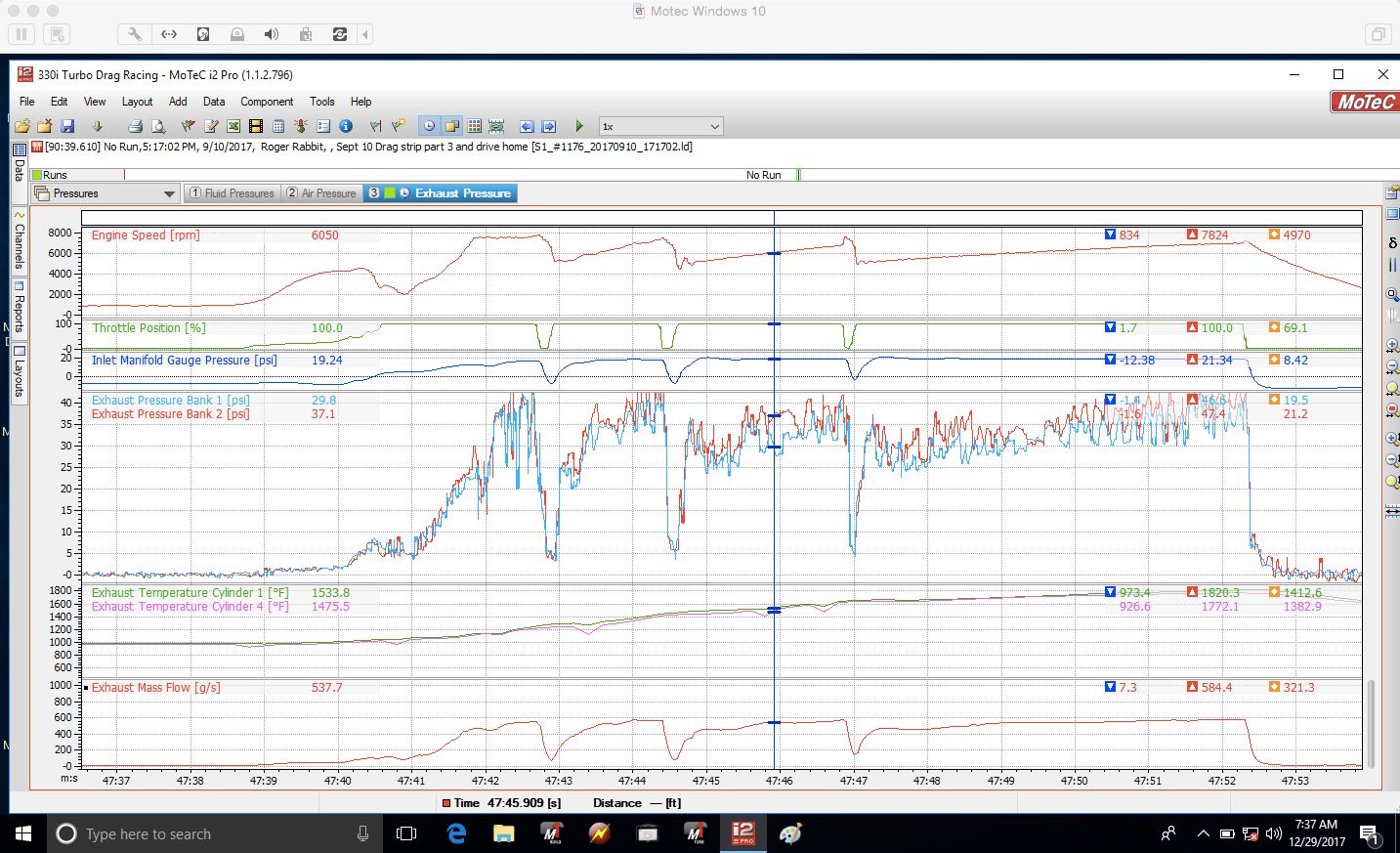
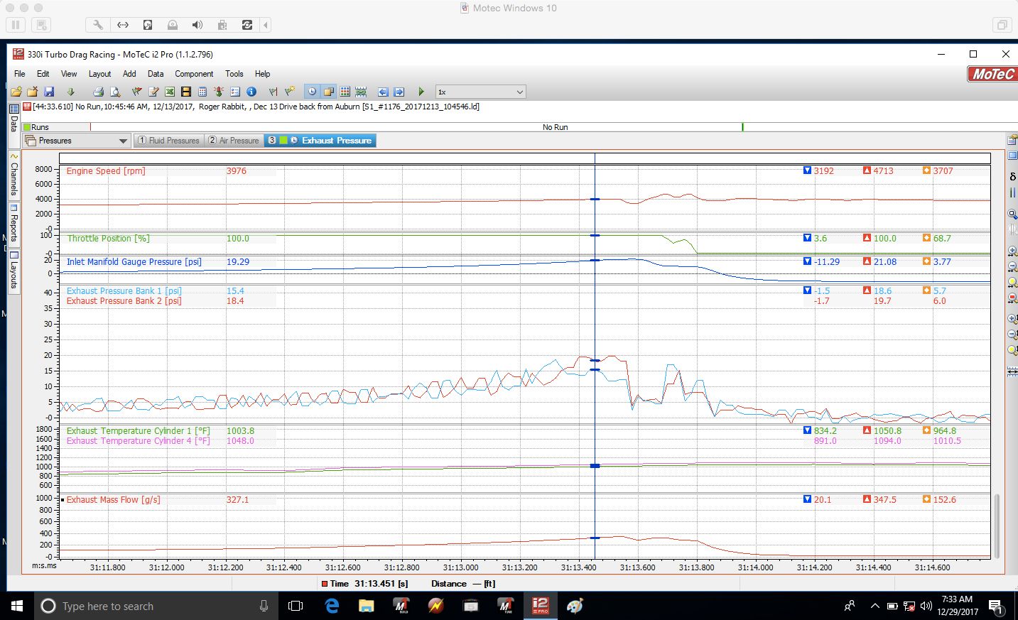
GTX30:
GTX40:
The GTX30 data is from the drag strip, and the GTX40 data is from road testing.
Last edited by PEI330Ci; 12-29-2017 at 06:42 AM.
M54B30 Inside
Another sample of the GTX40 in action:
Unfortunately, I really don't have a good apples/apples comparison between the 2 turbos, but it is interesting to look at.
Member
26237026_10155226141246915_1756259807_o.jpg
Open T4 with a Turbosmart Hyper 45 and 4Port. 10psi spring and control range is 10-32+psi...duty cycle around 50% at 32psi.
1000+RWHP, Lab22 Built Turbo S54 - BMW Half Mile Record Holder
Lead Disagreement Eng PE
You can also brace the WG pipe to the turbine housing to reduce the bending on the small fillet weld to the pipe off the housing.
I also vote TS Hypergate 45. I don't think it's that complicated to section the divider, and it definitely doesn't need to be 1/4" thick. 1/8" thick is plenty. Just cut the pipe down the middle with a 1/16" grinding wheel, dress a little, put 1/8" plate cut to shape, V notch pipe and go to town with a nice outside corner weld - done.
I think you'll have more than enough WG flow then. Maybe even enough without the top WG (which has horrible placement anyway).
Member
Why not try porting the manifold's WG as mentioned and then run the largest hot side AR since you plan to push the rpm to 8k? Both would help reduce boost creep and the larger AR will improve the high rpm power.
WOT
Member
That's never stopped you before. While I agree with you on that point, I'm sure you know an excellent welder somewhere around the world that could make that happen for you
Last edited by AlexQuattro; 12-30-2017 at 07:39 PM.
Member
I don’t think it’s a very good wastegate. Tested back to back against a Tial V44 and it had noticeably worse boost control. Others have tested against Tial MVR44 and found the Tial to be worse.
LICENSE SUSPENDED
Tial > turbo smart
Sent from my E6782 using Tapatalk
1996 332IS
Built 3.2
CES/Steed TS Precision 6466, spraying a "$π!℅" load of meth.
Technique Tuning 80# tune.
1/4 mile 10.84 @ 136.72
Your 1 and only stop for all your BMW performance needs
WWW.CESMOTORSPORT.COM
Cantry Member
You mean the TS is worse, right?
Lead Disagreement Eng PE
Really? I haven't used them myself, but I know quite a few people using them on pretty high strung track cars with no complaints. About the only thing that would affect "boost control" is flow area and friction on the valve guide.
The TiAL MVR is a nice setup too - use the water ports!!! It's a minor amount of plumbing, and seems to give a lot more reliability to gates that are under a lot of stress.
M54B30 Inside
Your 2 points contradict each other.
Porting the WG mounting would give marginal more flow, but running a larger exhaust housing (1.19) would further reduce the flow % through the WG.
Increasing the area for WG flow by 300% (vs what it is now) would potentially solve this issue without affecting the efficiency of the turbine housing. It would be a bit of a gamble...and I'd have to buy yet another WG, and do a bit of modification to my engine compartment to fit it.
Running one of the 2 Tial MVRs I have in my hands on the turbine housing would be lower risk from the flow perspective, but I don't like the fabrication side of it.
I also have a really nice PTP turbine housing blanket on the shelf that will fit on the housing the way it sits....but I've have to get something custom made to fit with the WG flange on the housing.
- - - Updated - - -
I do have a guy that I trust to do this. (Colby @ Luxfab)
 Posting Permissions


 Reply With Quote
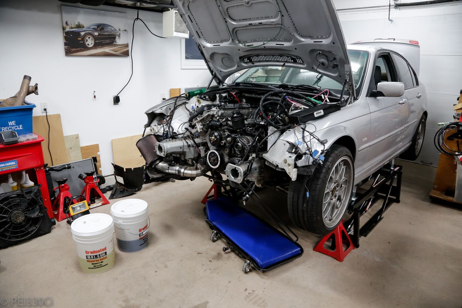

Bookmarks