
 Member
(Pointing finger at himself)Originally Posted by PEI330Ci

Lead Disagreement Eng PE
Yea, definitely looks like something kept the valves off the seats. You can hopefully get two new valves then lap them in, but the exhaust seat looks like it might have some nicks that will still remain after a lapping. That said, I wouldn't worry too much about them, as I'm imagine we're talking a few microns of width here.
Member
Slaps my forehead! I should have read more of your thread....you were running 15psi and had an FP drop and destroyed a plug. See, I thought you were still down around the 5-7psi mark (not that you can't destroy things at that boost level...).
Check those valves for true now as well. At a 1000M standing sprint 6 months ago, a buddy leaned out a couple of cylinders on his 2.3L 4G63 and DESTROYED a plug. The pieces of ceramic wedged up the valves and bent two of the exhausts. The mystery of what happened plagued us until the injectors were flow tested and two were found to be significantly down. So what blocked them? Only recently I discovered he is only running one of those 40-50 micron stainless gauze rebuildable units. When ID publishes an article advocating the use of <10 micron filters, peeps should probably take notice.
Anyway, good to know you thoroughly checked the head work before assembly. My new engine guy re-machined my valve seats (told him not to touch the Supertechs) and then blued and hand lapped each valve and numbered each one as well!
And what of the fuel rail pressure distribution issue? The bore of my rail has to be a good 13-15mm and I have fitted -6 ORB adaptors on each end. Can a rail with a bore this size really have distribution issues? What size is your rail?
I'd assume your ECU can do injector trims?
1989 E30 - M50B28 Turbo - ZF 8 Speed
M54B30 Inside
Ordered valves...but then realized it was July 4th...so nothing moving until tomorrow.
Going to lap the valves on installation and see what the seats tell us.
The ECU was doing injector trims, and covering up most of the fuel pressure fluctuation. Then I changed the correction range from +/- 50% down to 10% because I had dialled in the tune a lot more. So while the ECU was trying to compensate....I kind of cut it's legs off.
I don't think the fuel rail was an issue anymore. This rail is used on some other projects making a lot more power with smaller feed lines.
Good point on the fuel filter. I'm running a huge inline one from Aeromotive with a 10 micron paper filter.
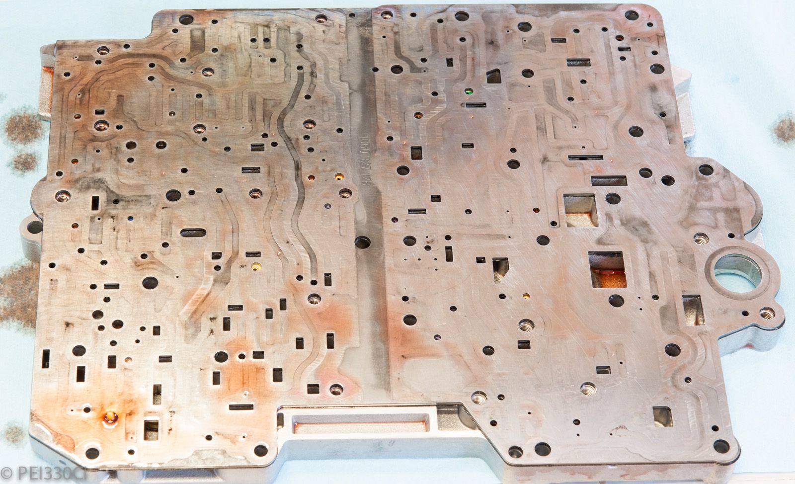
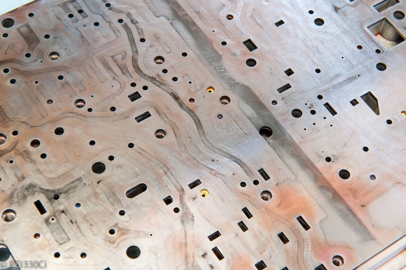
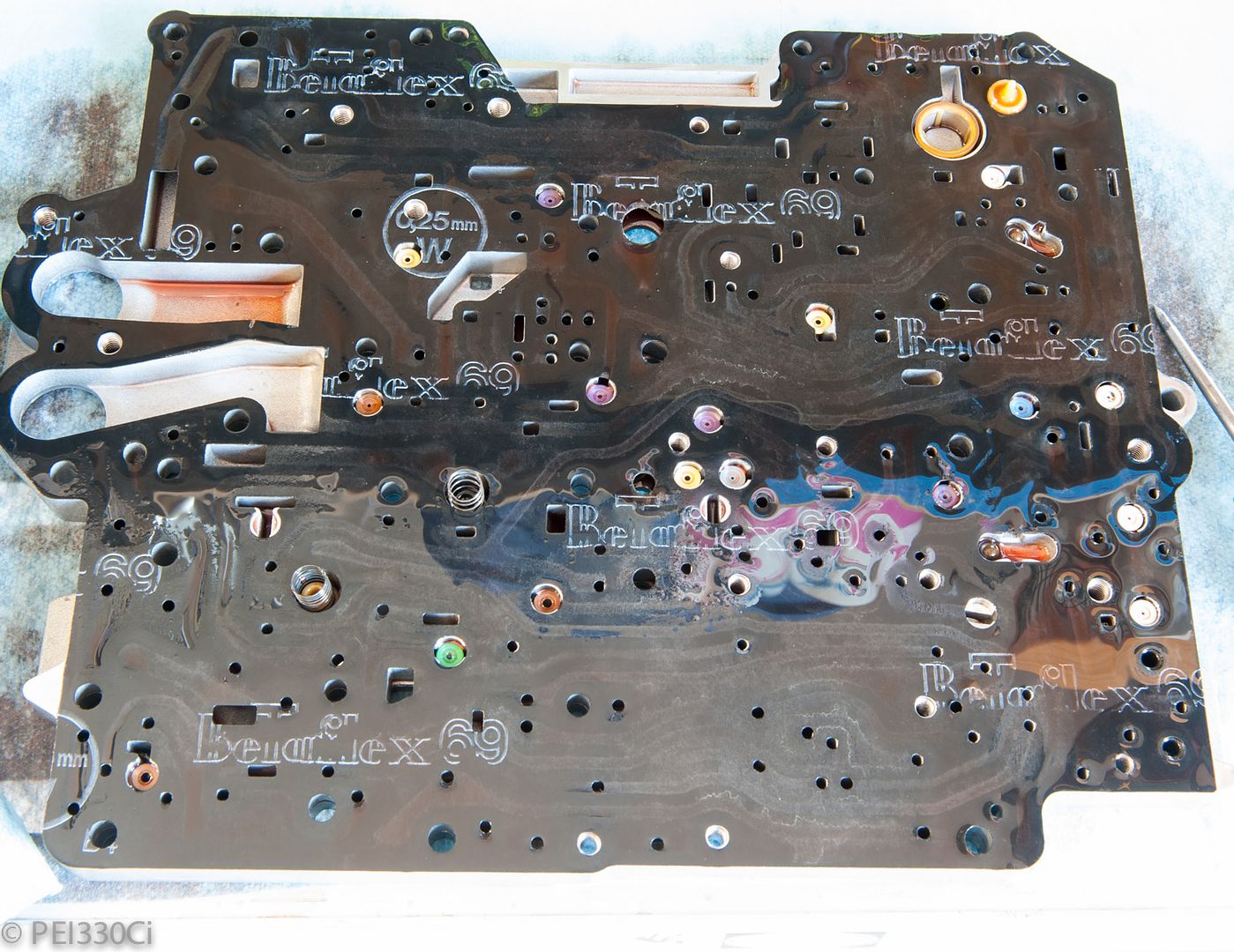
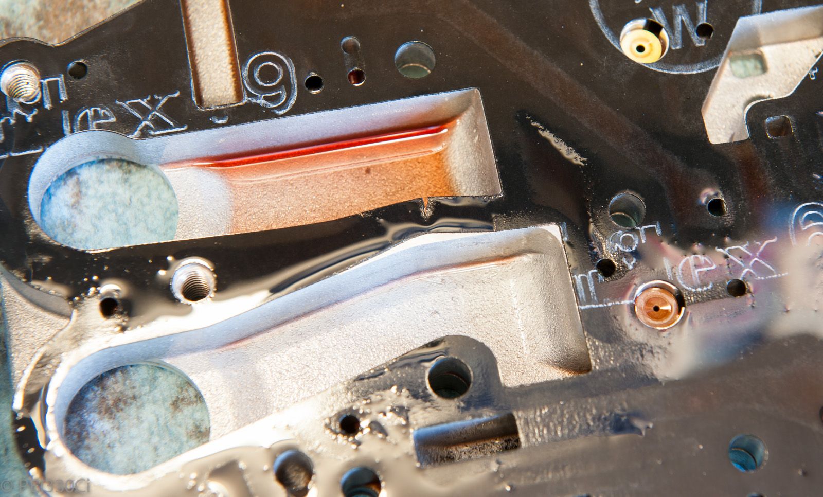
Well...I think I might have found "the" issue with the transmission. Tonight I was tearing apart the valve body, and found damage to the gasket between plates. The location is a divider between the oil pump's high pressure outlet, and the fluid inlet from the oil filter. In theory this would allow fluid to bleed out of the HP circuit, lowering line pressure. Now....I don't know when this gasket was damaged with certainty, so it's not worth throwing blame anywhere. I have never had the valve body apart before, so I don't see my own hands doing this in 2013. It is feasible that the gasket was damaged on assembly when the transmission was rebuilt. It is also feasible that I damaged it tonight when taking the valve body apart. But.....the later is not that likely, as I can see a trace on the 2 plates that the gasket goes between that shows a non-uniform line. In other words, it appears there was fluid bleed while the valve body was in operation. One other possibility is that by rev'ing the engine to 7600 RPM this spring, that the bypass valve was not able to keep up and the circuit blew out the gasket. I'm now looking for advice on sealing the new gasket on when doing reassembly. Pictures to follow maybe tomorrow....
Member
Yeck! Maybe make sure those two body faces are truly flat. Danger zone there cuz what glue could you use that won't potentially cause problems? Unless your application of said glue/sealant is super sparse.
1989 E30 - M50B28 Turbo - ZF 8 Speed
M54B30 Inside
Tearing apart the valve body:
This might have been an issue:
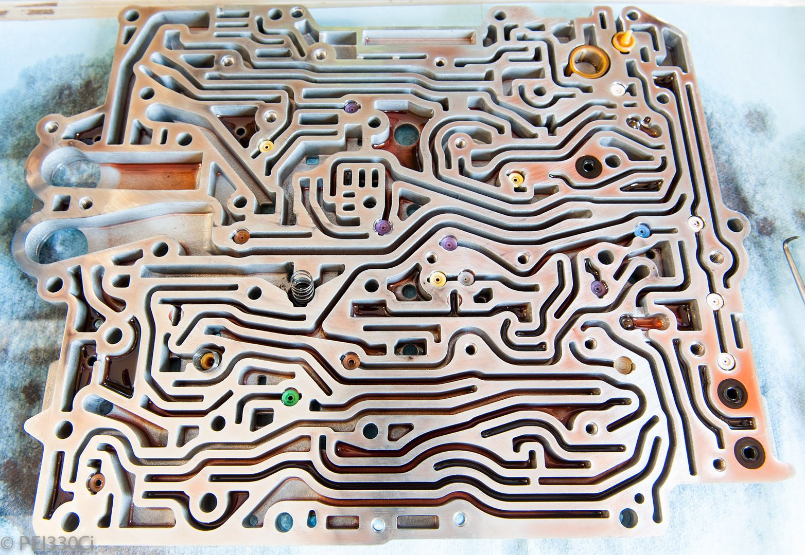
Channel plate:
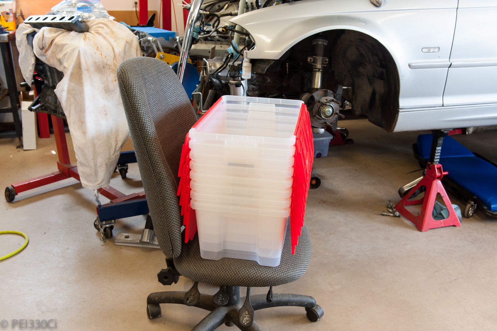
Now that I've got 7 clutch baskets to keep track of, I decided to get organized:
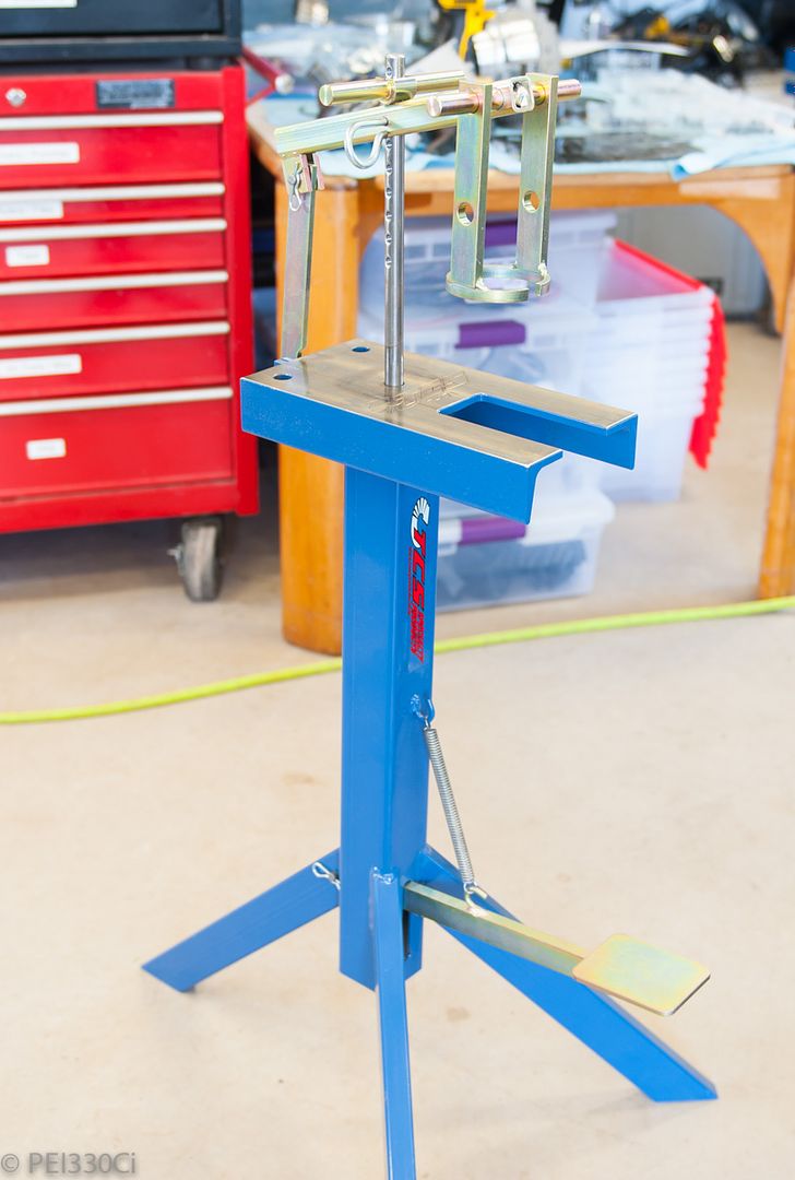
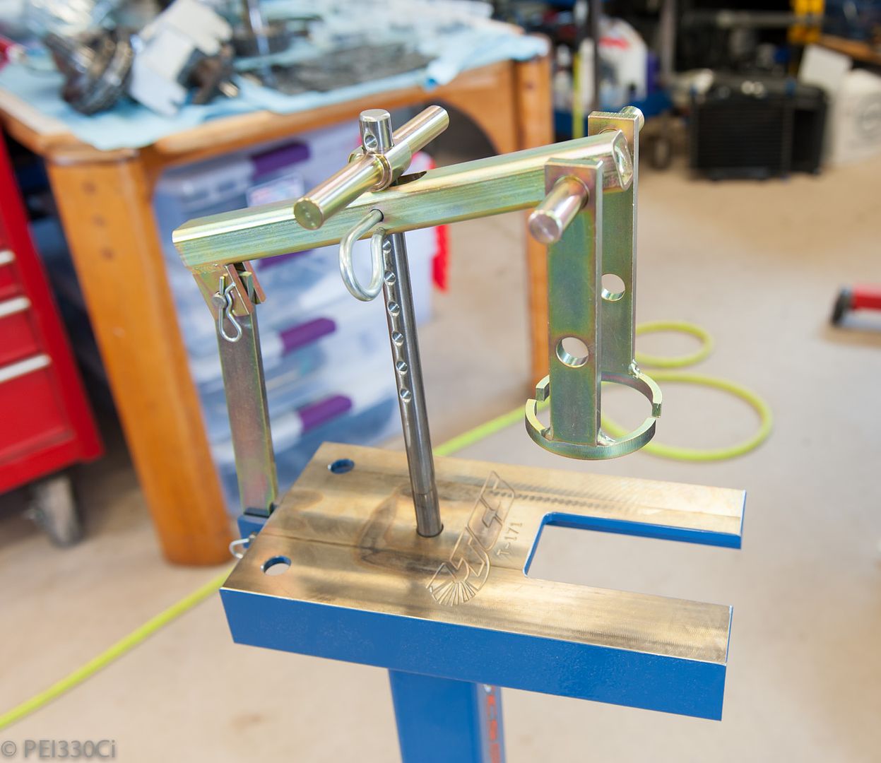
...and the foot press arrived to help with releasing spring clips:
I figured it was a good investment considering how much I might be working on automatic transmissions in the near future.
- - - Updated - - -
I'm going to get some help at the machine shop in measuring that surface.
This is what was recommended to me:
https://www.permatex.com/products/ga...-temp-sealant/
Luchador
Adam, thank you for sharing your adventures with us. So many people only document the good parts of the build, but the journey is where all the learning takes place. I have learned a ton from this thread and really appreciate everything you have shared.
HARDCORE Member
BMW CCA Member
I approve this build. M-tech1 Approved! You sir, are a god amongst men.
________ ________> Ich spreche die Deutschundich bin halb Deutsch. <
Member
Ditto.
--Peter
Member
Adam,
Do you have this build documented anywhere else like on a blog? There is so much good information and pictures here and I hate to see things like this kind of lose its value after years because of broken picture links and whatnot.
M54B30 Inside
Thanks gents
I don't have a blog.
The images are hosted somewhere I've found to be safe. (Same host for over 10 years)
Member
Crazy - I just spent about 20 hours over the past 4 days reading 9+ years worth of your BMW-related life history, Adam, and I almost feel like I know you. I like your way with cliffhangers and writing style
The NA build, the fire, the turbo build.. depending on how this all ends, it could probably be adapted to a Hollywood blockbuster- in all seriousness though, I am in awe of the fabrication going on here! And taking the time to document the project publicly, that's just amazing. I learned a lot!
A humble thank you here from Denmark(where we are not allowed to tune, and have 150% tax on cars).
During my reading, there were two things that made me wonder:
- I saw that you used copper spray on a head gasket - I thought the mating surfaces were supposed to be clean?
- How did you get the ZF parts and overhaul manuals for the gearbox? From my search, it seems to be unavailable to DIY'ers.
I'm looking forward to following this thread real-time. It is probably even more insane than the brits doing the Binky Project!
Oh, and please don't get hurt again, that was tough reading...
M54B30 Inside
The mating surfaces are supposed to be clear of debris, using an adhesive spray helps hold the gasket in place when under pressure. But....I made a mess of the installation...the gasket touched the duct plate a couple of mm off, and I wasn't able to lift it to reposition it. I'm now in the midst of ordering a new gasket, and I think I'm going to mask off the main part of the gasket, and spray only the high pressure oil pump output channel.
There are a number of documents available for free online for the 5HP19.
- Functional Description by Bob Cherrnay
- ZF Parts Manual
- ZF Repair Manual
- ZF 4 and 5 speed valvebody descriptions
I paid for the ZF 5HP19 Functional Description from ATSG, which I found VERY useful in understanding how this transmission works. I also paid for a PDF listing all of the port locations to test clutch engagements on most all ZF transmissions from ATSG.
One document that I have not found or purchased, is the ZF 5HP Valvebody Manual. It has detailed hydraulic drawings of how everything functions....but is $290 without shipping.
The most informative and helpful person that I have been contact regarding the 5HP19 is Nat Wentworth. He is with Eriksson Industries, whom I source all of my transmission parts from.
Member
Hi everybody, I'm new on the forum and maybe my english is not very good.
I'm building my M54 engine too and I would like to know if it is better to use a drill press to drill the whole for time-sert ,
Thanks
LICENSE SUSPENDED
Hilti hammer drill ; )
1996 332IS
Built 3.2
CES/Steed TS Precision 6466, spraying a "$π!℅" load of meth.
Technique Tuning 80# tune.
1/4 mile 10.84 @ 136.72
Your 1 and only stop for all your BMW performance needs
WWW.CESMOTORSPORT.COM
Member
Dude! It's his 1st post. You wanna start him off on the wrong foot?
JeanM54, if you can use a drill press it will make the drilling much easier, but it can be done carefully with a hand held drill. The drill guide plate in the Timesert kit makes it difficult to make an error. The kit is designed to be able to make the repair while the engine is still in the car.
Member
Hello jakermac,
thank you,
it is precisely to guide the drill bit I asked this question.
Boosted Member
Just looked through this entire build...great stuff! On getting more clutch surface area....have you talked to anyone about making custom single sided friction clutches? The other option to more clamping force is to increase the piston area of the holding piston. Maybe a custom drum made of a stronger material to allow thinner walls to increase the piston area. Also, if pressure goes up, you should be able to modify the firmness by adding a restriction in the VB.
Last edited by M3 Muscle; 08-13-2016 at 10:44 PM.
M54B30 Inside
A single sided friction disc only takes advantage of part of the total thickness added. If I have a 1.55mm 2 sided friction disc, and a 1.8mm steel disc, and I need another 0.4mm of clearance for the pack to rotate when not engaged, I need a total of 3.75mm of additional space in the drum. If I run a single sided friction disc, I'd still need 3.35mm of space for half of the added friction capacity.
I have been in detailed communication with transmission builders that are familiar with the 5HP19. Everything you mention above has been discussed; I ended up buying a lot of measuring tools to further understand options, and have also had a number of parts modified at a machine shop. Once I get everything running again, and I prove that it works, I'll be open to sharing what I've done. Until then....it's all just a theory....
Regarding line pressure: It's not as simple as domestic transmissions. There are 3 (Three) valves that fluid passes through before reaching an engagement piston. There are things that can be done to all 3 valves, but in the end I've chosen to focus on just one. (KISS)
The one thing that I haven't been able to find is a vendor that is willing to put OEM steel plates through the "Kolene" process. If anyone knows a guy....I would love to chat. What I'm looking to do is send a complete set of OEM plates for treatment....
LICENSE SUSPENDED
I'd imagine you have looked at these guys ? http://www.europeantransmissions.com/index.htm
Article
http://www.europeantransmissions.com...nsmissions.htm
1996 332IS
Built 3.2
CES/Steed TS Precision 6466, spraying a "$π!℅" load of meth.
Technique Tuning 80# tune.
1/4 mile 10.84 @ 136.72
Your 1 and only stop for all your BMW performance needs
WWW.CESMOTORSPORT.COM
M54B30 Inside
Yup!
They came up in a generic search for ZF 5HP19 transmission, and the Alto parts they re-sell are available from many others.
LICENSE SUSPENDED
A friend (of a friend) had a trans either built or sourced custom parts from them for a Porsche Boxter. He did a custom gt3071r build on one. His trans held up pretty good iirc.
Last edited by Butters Stoch; 08-14-2016 at 07:41 PM.
1996 332IS
Built 3.2
CES/Steed TS Precision 6466, spraying a "$π!℅" load of meth.
Technique Tuning 80# tune.
1/4 mile 10.84 @ 136.72
Your 1 and only stop for all your BMW performance needs
WWW.CESMOTORSPORT.COM
M54B30 Inside
Good to know, I might try to give them a call.
One of the interesting things I learned through this process was that "custom" steel plates are very very difficult to do. It's not so much about cutting to shape, but uniformity of surface treatment and how flat they are. Cutting the ID for example can cause the part to "cone" from heat. Then if you heat treat the part so that there is uniform "stress" through the part, you have a very tough time grinding the final product flat. If you're not very careful, you can end up with a clutch pack with more friction discs that handles LESS heat than an OEM pack, with LESS surface area under "clamp".
Another very useful bit of info was that in general, top steel ring thickness should be greater than 0.125". Using a top steel that is thinner results in uneven surface wear from the outside to the inside of the friction band.
Boosted Member
What is the reasoning that people won't do this? Process limitation when working with with thinner metals, or unknown treatment already applied?
I met a guy that sold his heat treat businesses to Bodycote a couple years back. I think it was more of a true heat treat in the traditional sense, not ferritic nitrocarburizing. I'll call and ask if he knows anyone that does this.
Member
Have you looked into EDMing? I know Multiplex has done EDM and all.
 Posting Permissions


 Reply With Quote
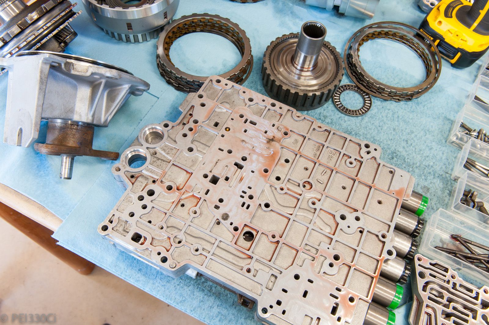


Bookmarks