
 Member
You definitely have a leak or your TB/IAC is staying open too much.Originally Posted by PEI330Ci

Depending on how much TQ reserve you require at idle, anywhere from 12-22 deg is where you will end up. IAC control you shouldn't need to have more than 15 deg of advance generally speaking as you don't need to ramp up engine TQ to maintain a higher/steady idle since that is what the IAC is for.
M54B30 Inside
Made me smile.
It uses IACV, but if in closed loop it can't get enough air, it can also move the TB up to a maximum value that I can set. Right now, the TB is at 0% all the time, and the IACV is at the pre-determined minimum of 15%.
Timing while in idle state is completely separate from the main timing table. I set the target value, then a minimum retard value, and there is no maximum. The closed loop control gives you P and I adjustments.
Both the Air and timing are controlled by a tune-able ramp-down. You can select the rate in RPM/second, when the ramp down starts above the idle target, and the decay rate exiting idle control.
Gents,
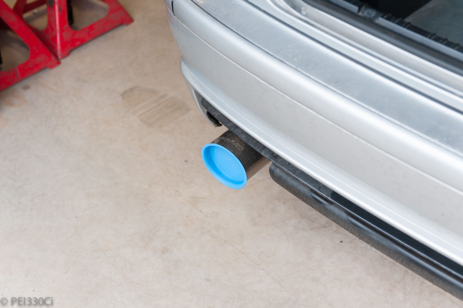
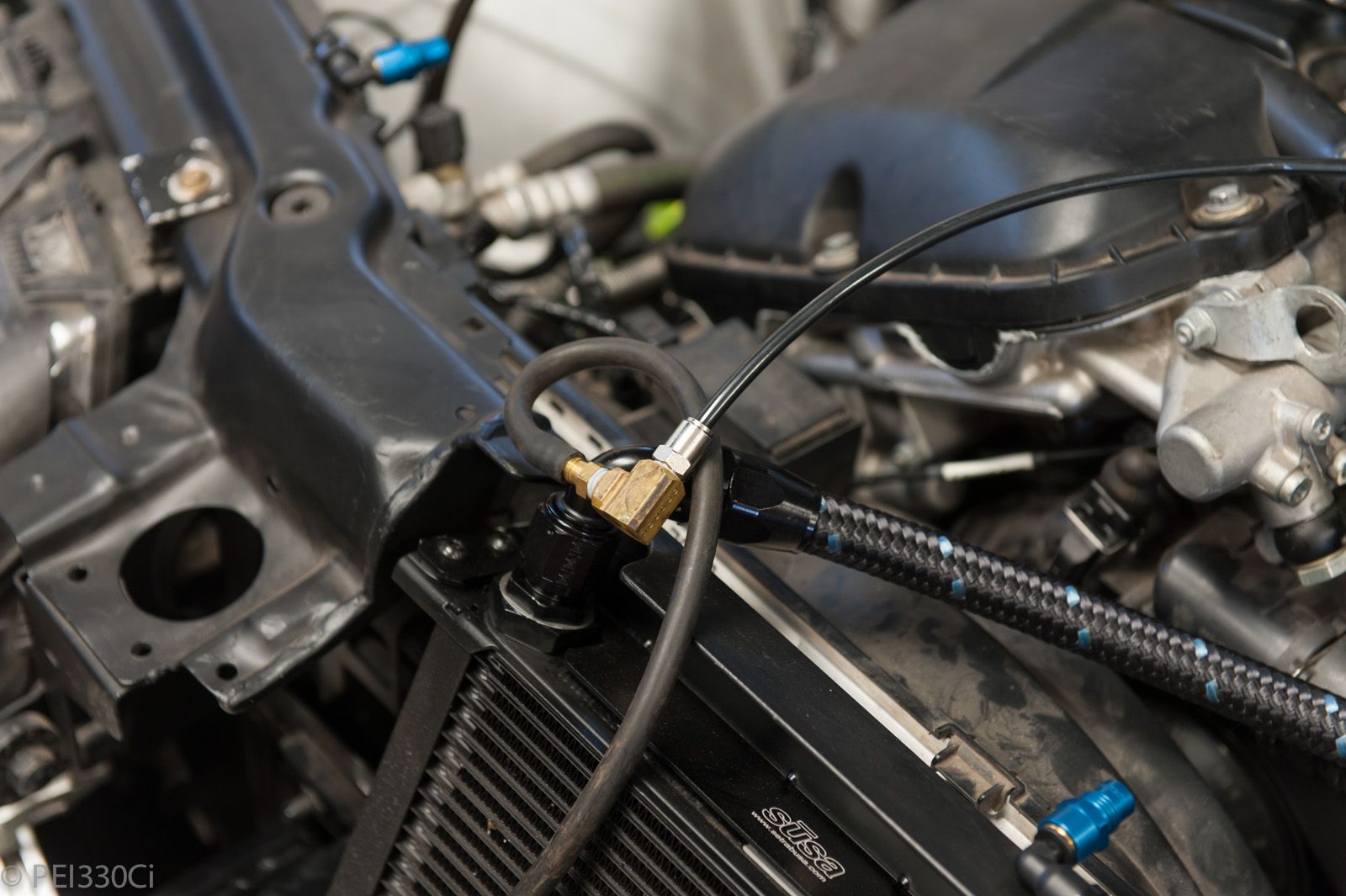
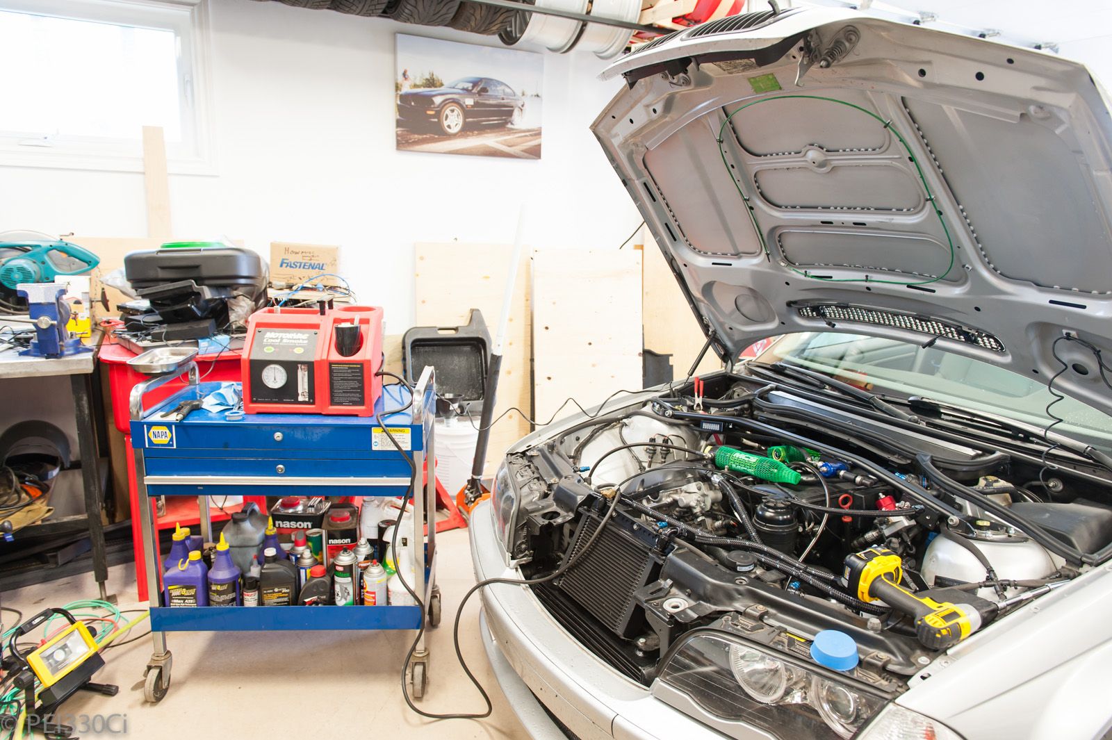
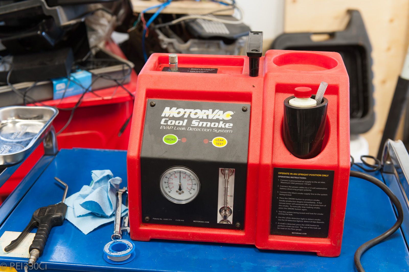
I’ve just hooked up a $1k MotoVac system (I borrowed it from a friend) to do a smoke/leak test on the intake. I plugged the intake before the IACV and TB, and the exhaust pipe at the back of the car. The smoke system was hooked up to the line that normally goes to the FPR. With basically the whole intake system intake, the only visible leak I found was from one of the press-fit “boost connect” system fittings, and it was so small it wouldn’t show up with my camera and a flash. On the MotoVac, it was showing a leakage value totalling a hole of 30 thousands of an inch.
I then disconnected the BOV, and WG plumbing, and pressurized the manifold to find a total of 20 thousands of an inch of leakage. To be fair, this could be from the exhaust system, which while plugged from the muffler, has a number of V-bands leading to the engine.
So I’ve found basically no major leakage in the intake and exhaust system.
2 days ago I took a timing light to the engine with timing set at a static value at idle, and at least visibly, it appeared to line up. (Within 1 or 2 degrees I would say, I’d have to pull the radiator out and put an indicator next to the crank pulley to get a 100% value, as there isn’t much space)
Yesterday I removed the IACV to confirm that it visibly functioned as directed, and it did. So a value of 0% was 0%.
The Throttle body at idle reads a position of 0%. (Which is actually a couple of degrees from fully closed)
The only think I can think of is that the turbo at idle is creating enough airflow that the engine can’t slow down enough?
I’m going to try running the engine now with the charge pipe off to see how that goes….
Member
Nope.
Good idea.I’m going to try running the engine now with the charge pipe off to see how that goes….
If you give the car a normal ign value @ idle, what does the car idle at?
Are you sure there is nothing in the Motec that is commanding the IAC (PID active, etc)?
Throw up some logs of the car running, I can have a look and see if I see anything odd.
But If you're idling high you have a source if air getting into the motor that you're not controlling, it's as simple as that.
Member
I run 16 deg advance at idle, pretty much fixed, with an IAC DC of about 43% for around 900 RPM - 1000 RPM
Hardest part about tuning this sort of thing is knowing what other modifiers run on your car at the same time. Check for coolant/air temp modification of idle speed/valve/ignition.
M54B30 Inside
Ran the engine with the charge pipe off, and same issue.
Killed the engine by putting the palm of my hand over the intake pipe; it held vacuum for a few seconds before I could pull my hand off easily.
There is one last thing to look over, and that is the throttle body calibration. It does sit open slightly at rest, and I think that is the calibrated 0% value. (Probably the factory spring fail-safe position?) Later I'm going to work on calibrating it so that fully closed is 0%. This is very likely now my mistake...
There are no modifiers adding DC to the IACV, or the Throttle. It's not that it's not possible, I just mean that the actual position is target position. After the initial cranking, the TB goes to 0%, and the IACV to 15%. (That's where I have it set)
What is great about this setup with M1 Build, is that I can check most calculations and associations of all the control parameters. If there are hidden corrections in the code, I can read them....
Thanks for the comments and advice guys! I'll keep you posted.
Member
Throttle body should stay fully closed and the ICV control the idle speed.Most of the drive by wire throttle bodys stay little open when are not powerd.
Last edited by George318; 05-30-2016 at 01:07 PM.
Member
Most systems will allow you to see individual alterations as well. Otherwise it'd be super impossible to figure out what's going on.
That said, it has to be your throttle stop that is posing the issue. 15% DC on the IACV is not enough to idle the engine. You're using the typical BMW 3 wire unit, right? That sounds about 1/3 as high as it should be in order to idle the engine. That would indicate to me that the throttle is gapped too far. I'd recommend plugging the IACV hose so it cannot alter idle. Set the throttle so that the car idles low maybe 600 - 700 RPM. Then, bring in the IACV. That's always worked for me.
u owe my mule an apology
The throttle should be completely closed at idle. Once you fix that it should come into line
86 325es, 2.8L m50, S476sxe, ProEFI 128 ecu, e85, solid rear axle, TH400 trans, 28x10.5w slicks, zip ties, popsicle sticks, tape
best time 9.06 @ 151.8 mph, best 60 foot 1.30
Member
Wait, this car DBW? if yes, why do you have an IAC?
If you have an external IAC, there should be no need for the throttle to stay open and as you said it's the source of your air "leak" also TPS = 0 doesn't mean squat for the actual position that all depends on the calibration.
If you're running DBW, I would delete the external IAC since you don't need it as you can use the DBW TB for IAC duties and you can eliminate another potential failure point.
Member
Just for your information, even a stock M54 with DBW throttle does come with an idle control valve. Thought of letting you guys know if you weren't aware of it.
M54B30 Inside
The idle system has it's own sub-manifold, and ports in cylinder head. They promote swirling in the combustion chamber to get a better burn at low throttle angles.
Why don't I eliminate it? At very low airflow levels, this subsystem gives better cylinder to cylinder distribution, and has a greater resolution of airflow control.
Member
I see BMW chose to make it complicated lol
Anyway, at least you know why it's happening!
M54B30 Inside
I think I do...and everyone's comments here have been very helpful.
Just need to find the time tonight to recalibrate the DBW TB.
In other news, I have twice now had the ECU trigger the Fuel Pressure failsafe, which cuts fuel/spark to drop RPMs below 2000. The AFR during these events stayed perfect due to pressure compensation in the fuelling. The reason why the pressure dropped was because I ran the surge tank dry. I've got an issue with filling it that I'm currently working on. I've been manually triggering the pump in the main tank to fill it while parked.....listening to how to tank sounds to tell when it's full. Not the most efficient method. There is some kind of restriction in the return line between the surge tank and main tank that is causing adverse pressurizing of the surge tank when it's full. The result is that the fuel level sensor ends up leaking....
Member
Re. Surge tank issues, did you happen to see the notes from Mikes thread? His issue ended up being the (lack) of a vent on the surge tank. Just off the top of my head anyway. So maybe check that.
M54B30 Inside
Yup, I saw his adventures.
I've got a -6 AN line from the top of the surge tank back to the main tank. It connects to the port on the tank cover that the return line from the OEM FPR used to connect to. Inside the tank, there is something called a "suction jet" that uses the return flow to pull fuel from the driver's side of the tank, to the passenger's side of the tank where the OEM fuel pump is. I suspect that increased flow that I've created running into the surge tank, has overloaded the flow potential of the return system back into the OEM tank.(Inside the tank)
- - - Updated - - -
I recalibrated the DBW, then worked on correcting the tune for both normal throttle based maps, and the Idle Control maps.
Car is running much better....I feel like there's a good baseline to tune with now.
M54B30 Inside
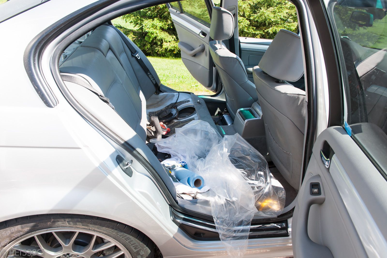
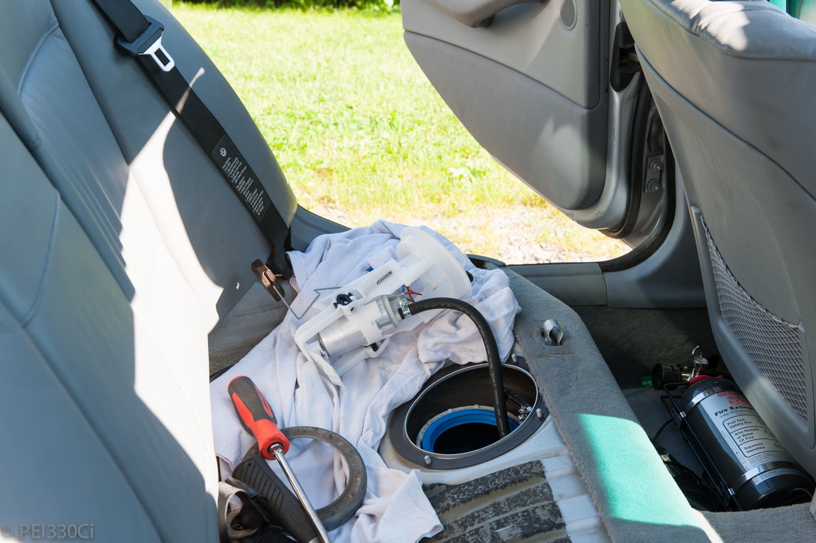
Responding to intermittent strong fuel smells, I pulled the back seat...to find that damage to the OEM fuel hangar from 2011 (I think?) was causing fuel to leak inside the "cap".
Luckily, I had 2 brand new fuel pump hangers and rubber seals on the shelf.
I transferred the -6AN bulkhead from the old hanger to the new one, and it was an easy install.
Removing the suction jet on the driver's side, and installing a 2nd fuel pump hanger was not easy. The fuel tank on the driver's side was completely full, and the suction jet and level sensor didn't come out that easily. Trying to install the fuel pump hanger, the first thing I found was the level sensor hit the hump. (tunnel) Bending it around to get clearance, the next thing I found was that the hanger assembly bottomed out before seating. I honestly tried ramming it down compressing the level spring assembly, bit it didn't work. So I pulled the hanger out, grabbed a flashlight and rod, and started searching inside the tank for obstructions.....which I found none. The tank was shallower on the driver's side than the passenger's side. I put the hanger in a vice, and cut off material from the "hoop" on the bottom creating about 2" more clearance. I also moved the fuel pump up about 2" so that the bottom of the filter was at the same level as the revised hanger hoop. The revised fuel pump hanger finally fit.
Next, I dug through my 330Ci stash (Parts from turning the black car into a race car) to find a connector and wiring that would mate to the OEM fuel pump hanger. So that's where I'm at now....wiring in both fuel pump hangers into the Motec system.
I will share that doing a test run of the pump feeding the surge tank, that it seemed to run quieter, and also there was much less back-pressure in the surge tank from having the suction jet removed. I used to see about 7 PSI on the FPR when running the fuel pump feeding the surge tank,(With the main pump off) and now I'm seeing 0.3 PSI at the FPR. That is a serious reduction in restriction!
M54B30 Inside
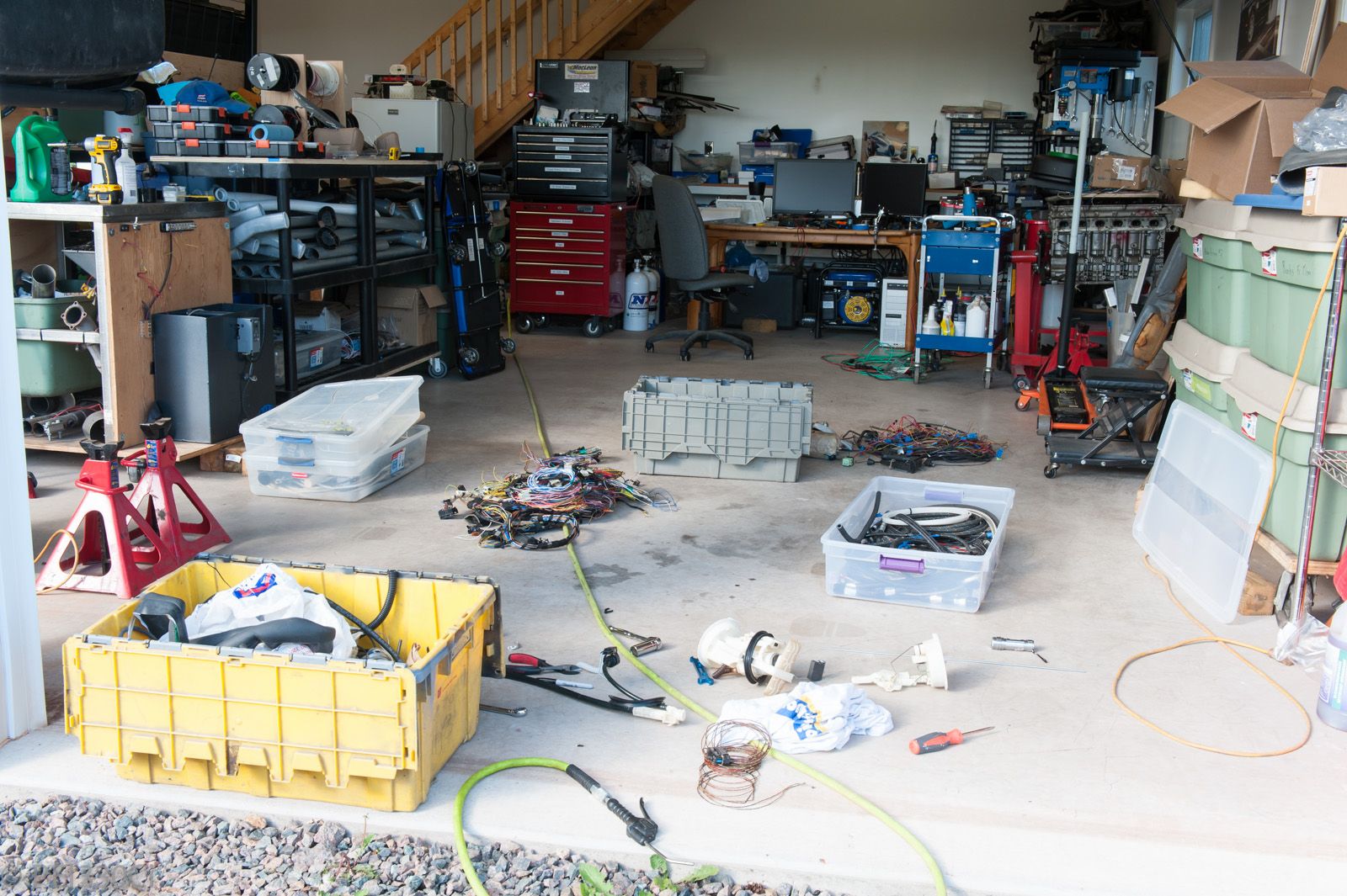
I've done so much in the last few weeks, I don't really know where to start. I also didn't take many pictures. Below are some highlights.
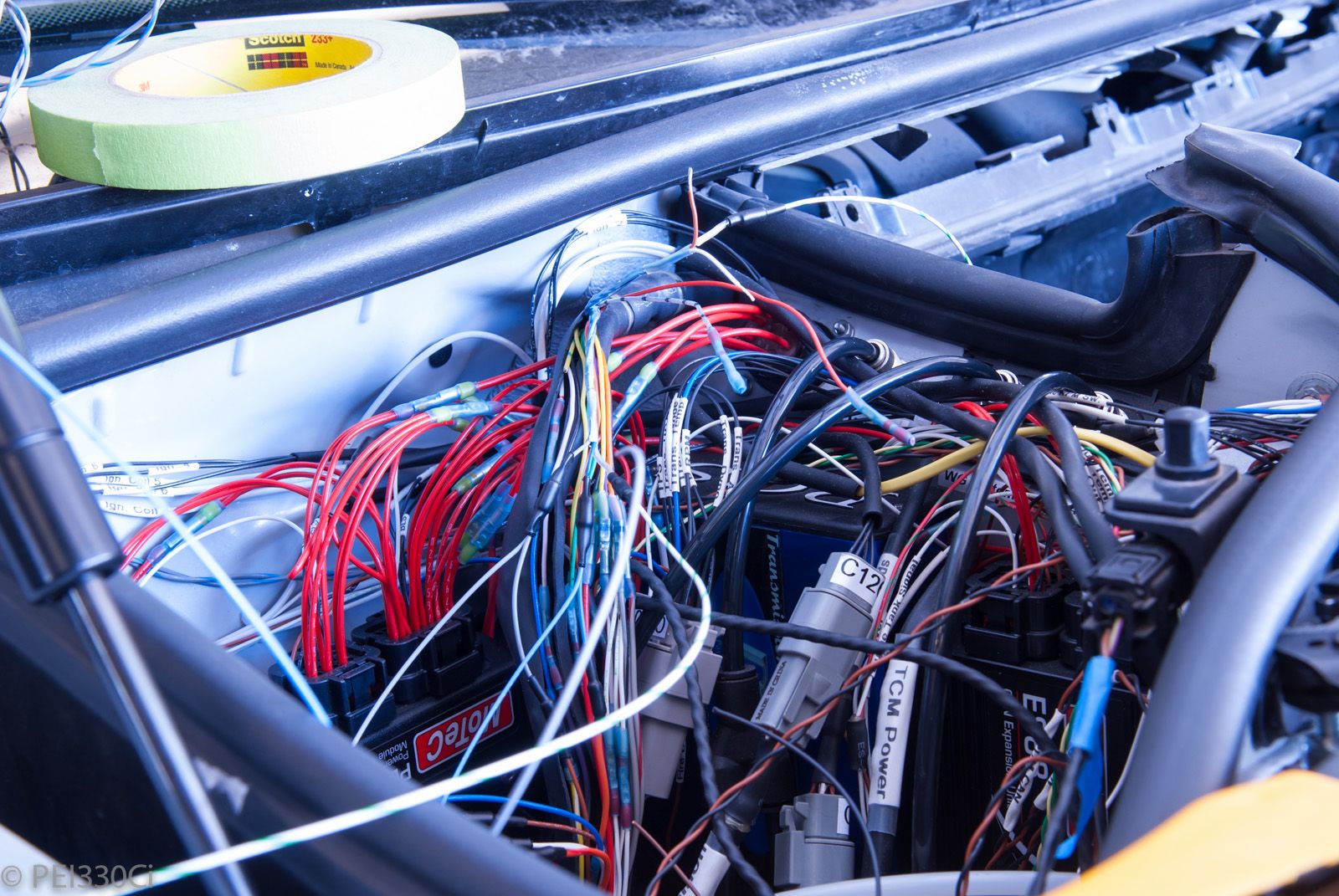
Tapping the transmission harness get signals for logging with Motec:
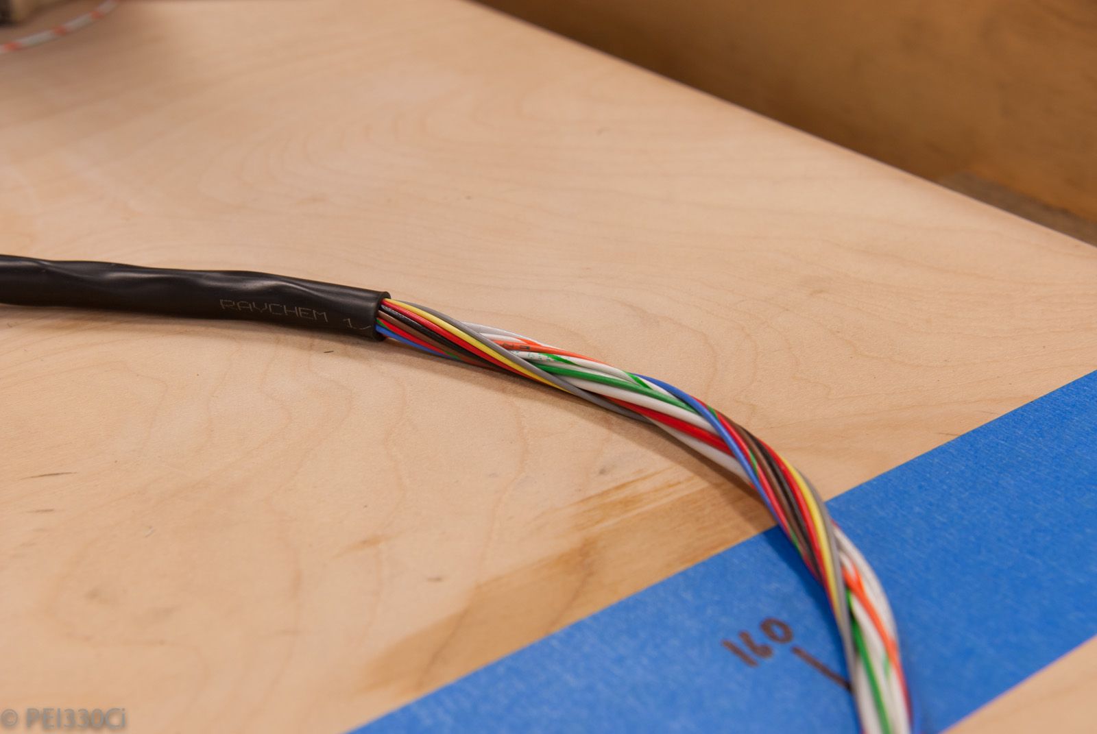
The start of a 22 foot harness to add more features to the fuel system:
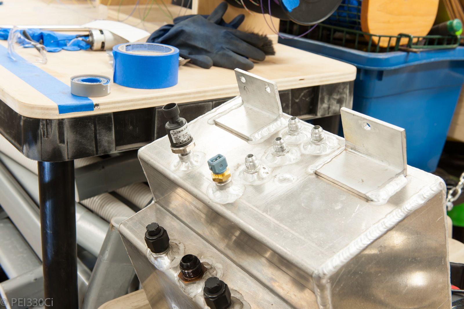
The core:
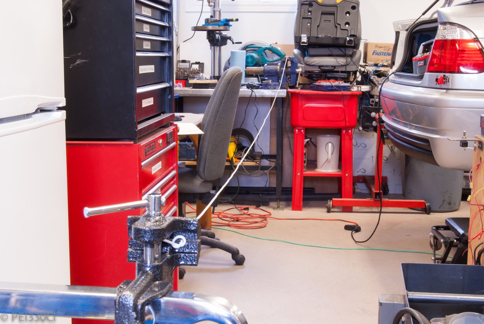
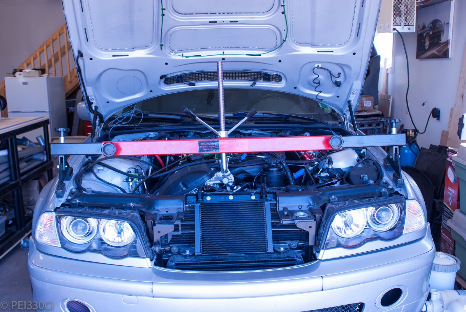
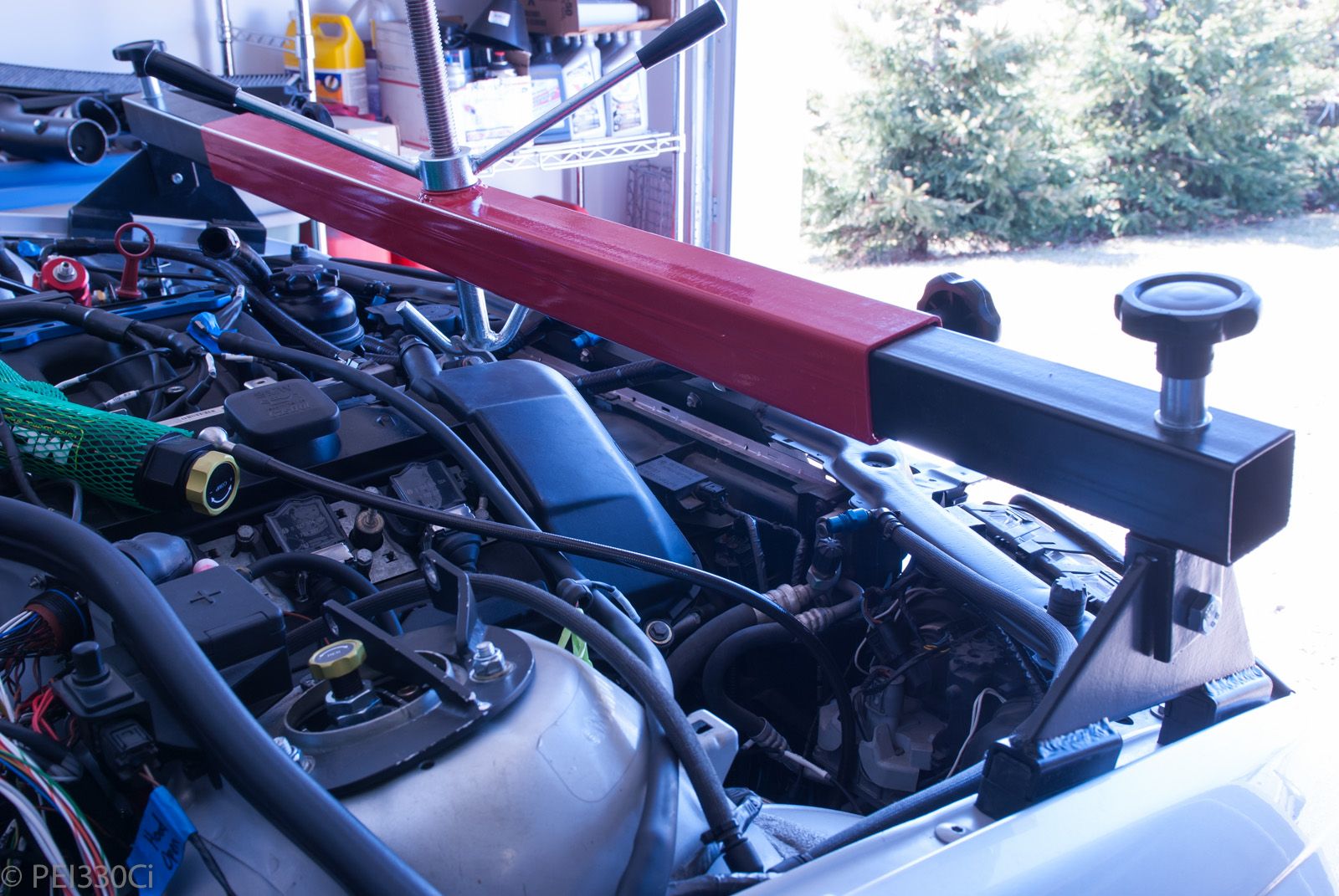
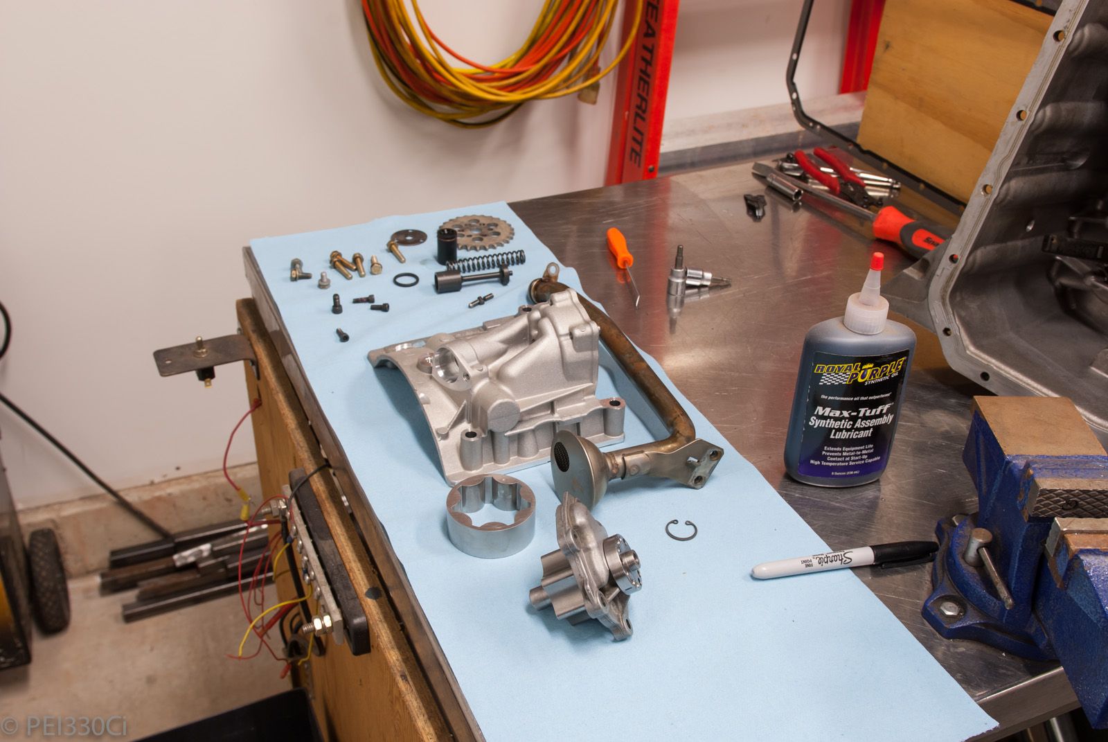
Supporting the engine to pull the oil pan off:
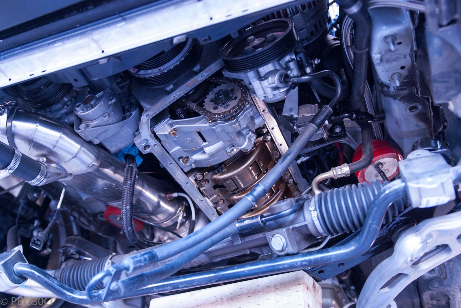
Oil pan off:
Stripping and cleaning the oil pump:
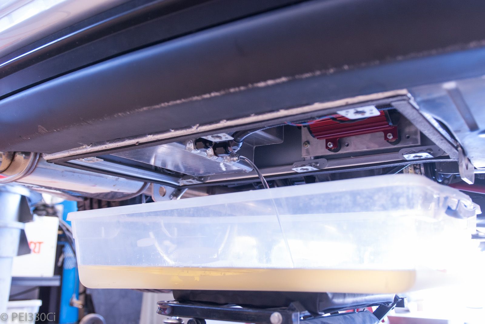
Fuel system (Surge tank) getting drained:
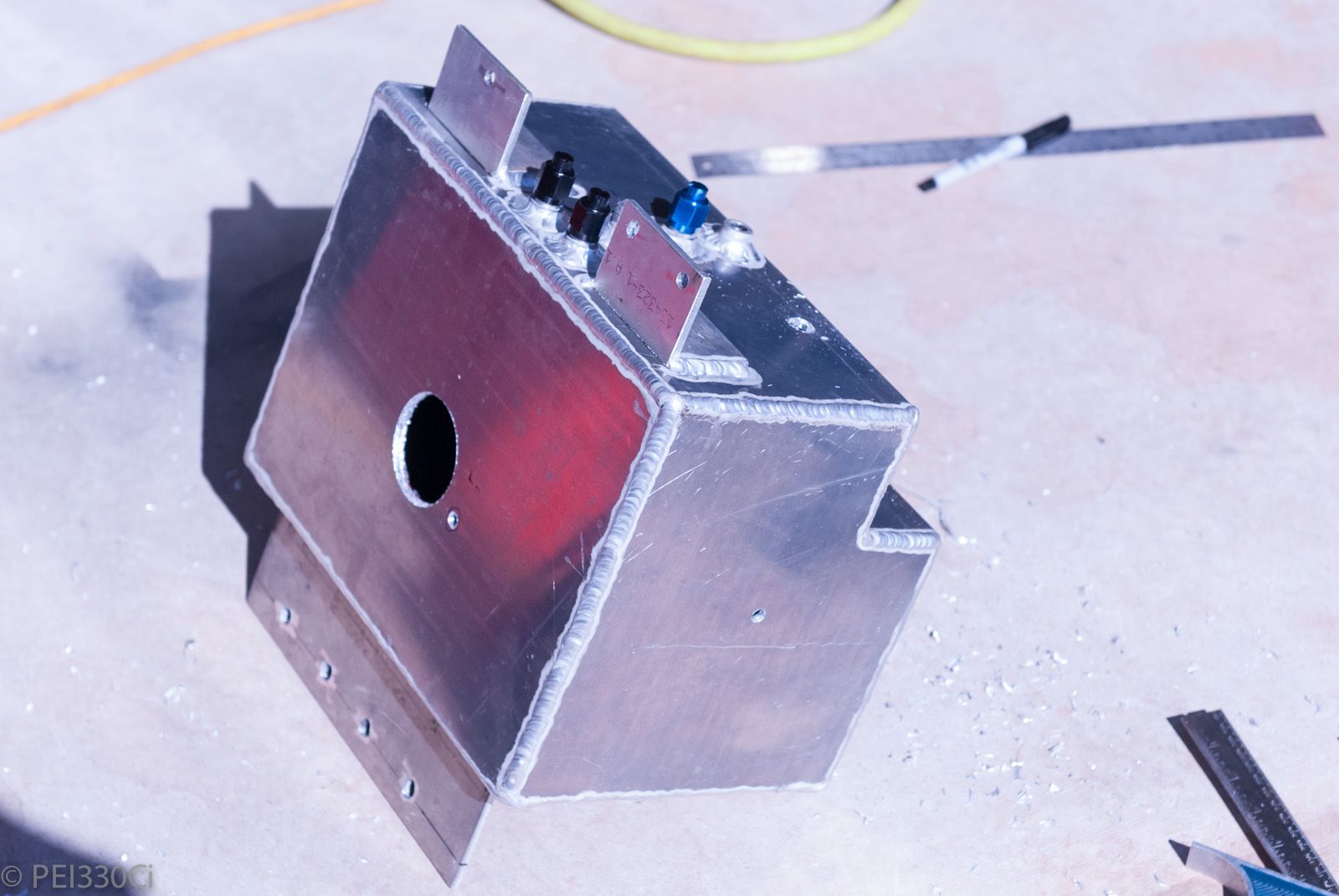
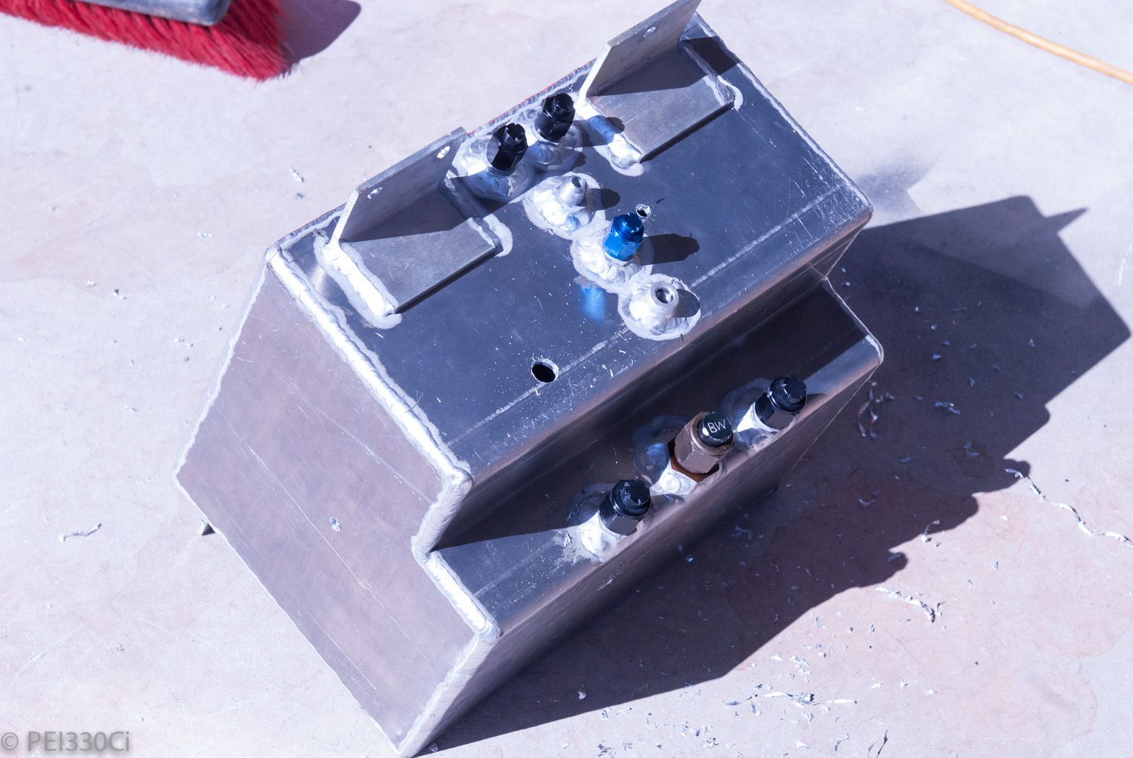
Getting ready for welding support poles through the tank to help with holding pressure. Also put a hole in the top for an ATL level sensor:
Hole for 1/8" NPT bung to be welded on for pressure sensor:
Welded up and ready to go back in:
Pressure testing the entire intake and exhaust system:
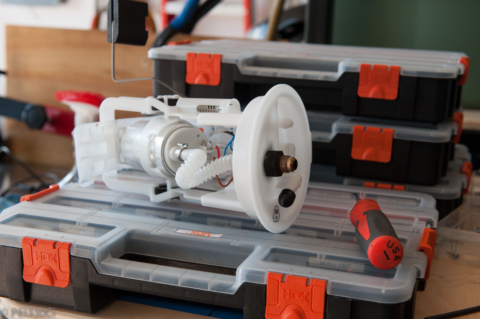
New OEM fuel pump hanger with -6 AN bulkhead added:
Putting the new pump and hanger in:
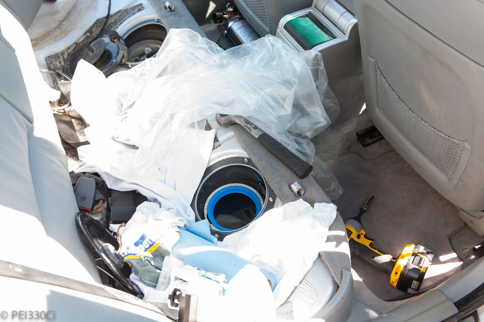
Trial fitment of pump hanger on driver's side:
It didn't work. Tons of sweat and swearing ensued. Eventually I got it to fit by bending the level sensor around, cutting 2" off of the hanger assembly, and moving the fuel pump up 2".
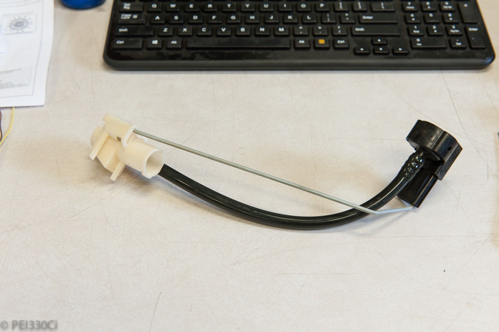
Searching for an OEM fuel pump connector (left-over from the Black car)
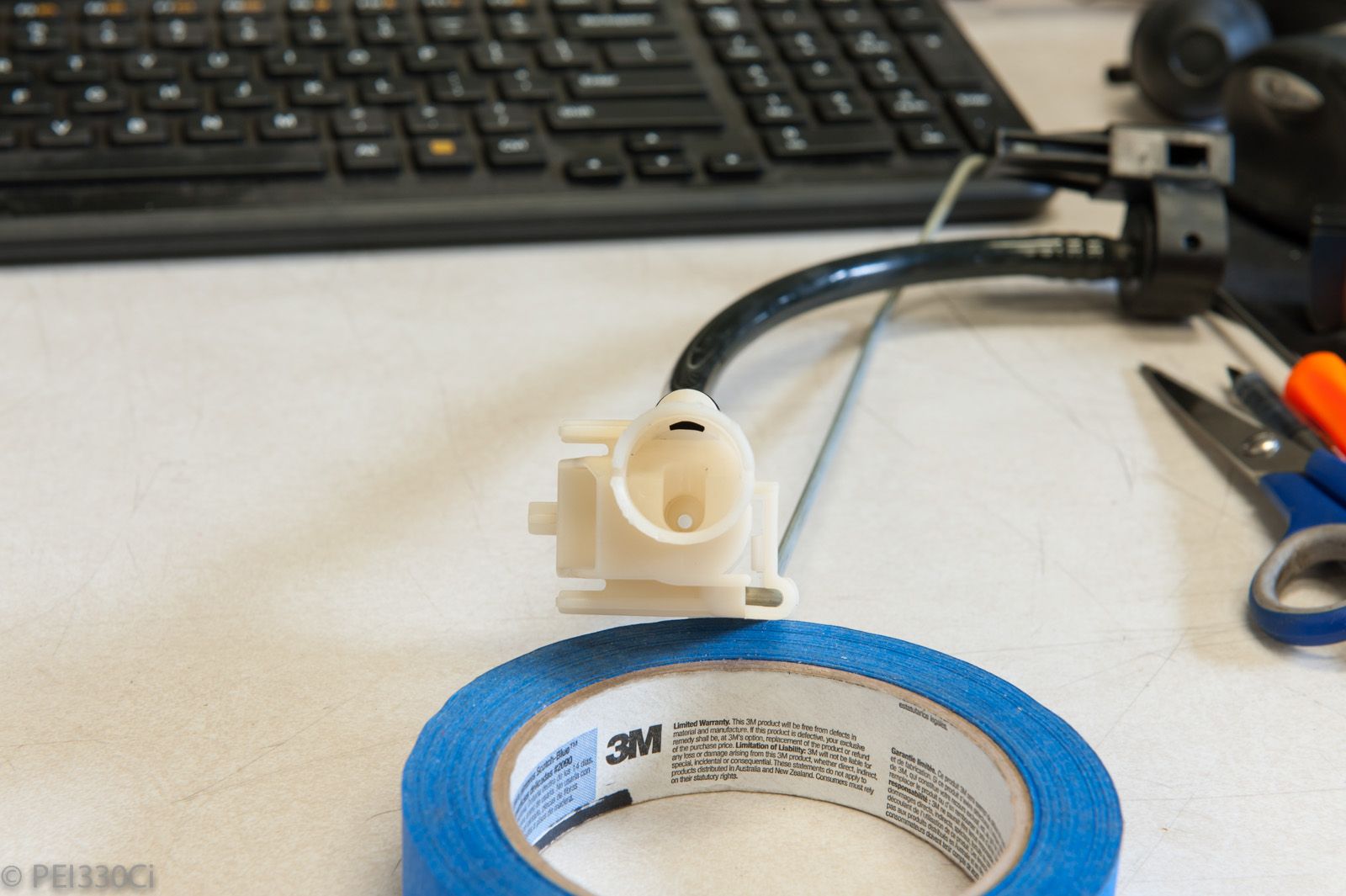
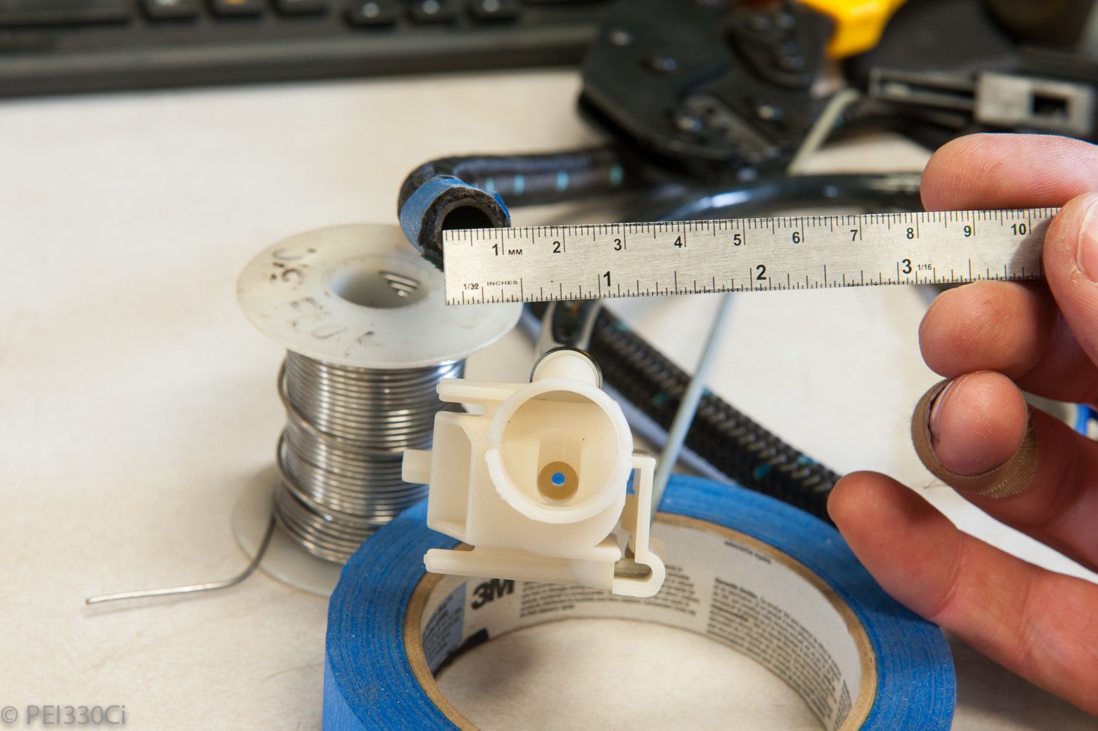
The infamous "suction jet" assembly:
Yup....return fuel is supposed to go through that little hole:
-6 AN line = 8mm ID
Suction jet = 2mm ID
No wonder filling the surge tank caused the FPR pressure sensor to read 7+ PSI with the main fuel pump off.
The FPR now reads 0.3 psi when filling the surge tank.
Now I just have to wire all that stuff in.
M54B30 Inside
This is getting good!
Started setting up the WG solenoids; one for the top and bottom ports of the WG. With both connected, not tuned, I've got too much response....I hit a Peak manifold pressure safety feature really fast at part throttle.
Using just 1 WG solenoid, and no PID tuning, I've got a 10 PSI aim map that's working very crudely. The main thing was to test that the systems work....and boy do they ever.
I can't launch in 1st gear by brake boosting with 10 PSI....it blows off the tires.
Starting to think about going to a dyno now that stuff is working....
u owe my mule an apology
Sweet! What rpm does it stall at? Any plans for some drag radials?
86 325es, 2.8L m50, S476sxe, ProEFI 128 ecu, e85, solid rear axle, TH400 trans, 28x10.5w slicks, zip ties, popsicle sticks, tape
best time 9.06 @ 151.8 mph, best 60 foot 1.30
M54B30 Inside
No drag radials or slicks at the moment, I'm trying to keep the driveline together.
Stall is probably 3000 RPM....but it's hard to tell until I get the boost control setup. As you know, the more torque you make, the higher the stall....
Looking at data logs from the transmission controller, it's not so simple. I'm still blowing through clutch packs (Gears) at varying throttle points. Sometimes you think it is line pressure, then when you look at the data it was a gear shift where the release point and engagement points don't line up. Reduce the throttle angle by 10% and the same shift is fine. Put the car in "a" gear, and then go WOT, and everything is fine though....
u owe my mule an apology
yeah I was curious how much time would be involved in tuning the engagement and release points of the clutches. People make there careers doing that.
86 325es, 2.8L m50, S476sxe, ProEFI 128 ecu, e85, solid rear axle, TH400 trans, 28x10.5w slicks, zip ties, popsicle sticks, tape
best time 9.06 @ 151.8 mph, best 60 foot 1.30
M54B30 Inside
It is quite frankly, overwhelming at this point.
I'm in the midst of sorting through basic issues, so I can start sending a tune and datalogs to a professional.
Member
Adam sorry I forgot to post this - was in DTA this weekend setting up weird stuff (like a pit speed limiter lol)

M54B30 Inside
Thanks Jon
That's the same #s I've got.
- - - Updated - - -
I'd like to thank everyone that has posted in this thread:
http://www.bimmerforums.com/forum/sh...gnition-tables
It's been a good setup reference.
Last night I bumped the boost target to 15 PSI, and worked on the feed forward table some more. No PIDs. With a 4 PSI spring, which effectively sees 5 PSI under load, I've been using 72% duty cycle on the WG to hit 15 PSI. I think that's as far as I'm going to go right now until I get on the dyno. The main thing being that to get the engine under load and do a pull covering decent RPM points, I have to hit some serious speed.
Today I was fine tuning the efficiency table some more after finding incredibly rich spots in the data logs. How rich? Lambda of 0.65. It was so bad I thought I had some kind of safety feature cutting power.....I was a little embarrassed to see that there was nothing going on with the DBW TB, Ignition timing, or fuel. Most cells I haven't tuned yet under load I'm leaving quite rich...and I hit a wall of them when I increased the boost target to 15 PSI.
The transmission is still doing wonky stuff under load, which doesn't seem to correlate to line pressure PWM. I "think" it might have to do with transmission fluid temps...which I've had wrong from the start. Yesterday I bought one of those laser temp guns, and today I re-did the calibration table for the transmissions internal temp sensor. I did this by putting the car in drive, with the parking brake on so there was load on the converter, and then just let the engine idle. I then used the temp gun on the transmission oil cooler, which didn't have the fan on or any air moving over it, to get "real" fluid temp. I then used the actual voltage reading on the Transmission Controller, and the M150 ECU, to correlate with the temp gun reading.
I'm waiting for the trans to cool off to ambient before going out and doing some test runs to see if the fluid temp is the issue.
What is wonky? I'm getting transmission slip under load, but it's not consistent. At 5 PSI of boost I was sometimes getting slip starting at 4500 RPM in 2nd gear. With the same line pressure settings, and 15 PSI of boost, it hasn't slipped at 4500 RPM....but it does do this close to 6000 RPM.
I'm not sure if this is a temp issue, an oil volume issue, or something else in the transmission software setup.
I also haven't been able to get the torque converter clutch to lock up. Even though it's programmed in the software, there is no physical engagement, and more telling, the lockup indicator on the GUI hasn't lit up. I have to go over my wiring again before I do anything else with this. But......if I can't get the TCC to lock up, there is no point in going to the dyno. Tuning part throttle load cells on a converter is like trying to measure a sponge with vernier callipers.
Member
Adam you might find that 0.65 is at the end of the scale for the sensor/controller. It might be much, much richer, depending.
 Posting Permissions


 Reply With Quote
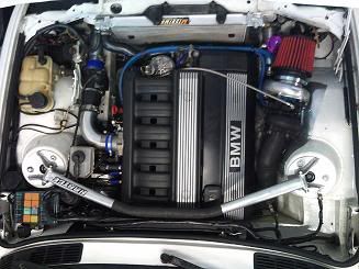

Bookmarks