
 Lead Disagreement Eng PE
Hey, I gotta do everything I can do to even hope to see sub 30 C IATs for part of the year!!! Usually it's in the 40+ range because ambient is around that.Originally Posted by PEI330Ci

That poor S2000....
M54B30 Inside
The following is how I tune the VE table without using a dyno.
To start with, the Motec M1 ECU has a very powerful closed loop fuelling system. You can setup compensation limits well outside of what you'd find with an OEM level ECU, and get reasonable results. That's not to say that the VE table shouldn't be tuned as carefully as possible, but using a basic starting point, you can get pretty far with closed loop control.
To further refine my base VE table, I came up with a system of data handling that pairs the M1's logging, with an Excel spreadsheet. To start with, I export a .csv file from i2 Pro at a sample rate of 10 hz, for every logged channel. In my case, this is nearly 700 data channels, so the file size is a bit large.
Here's what the i2 Pro data output looks like when I drop it into Excel:
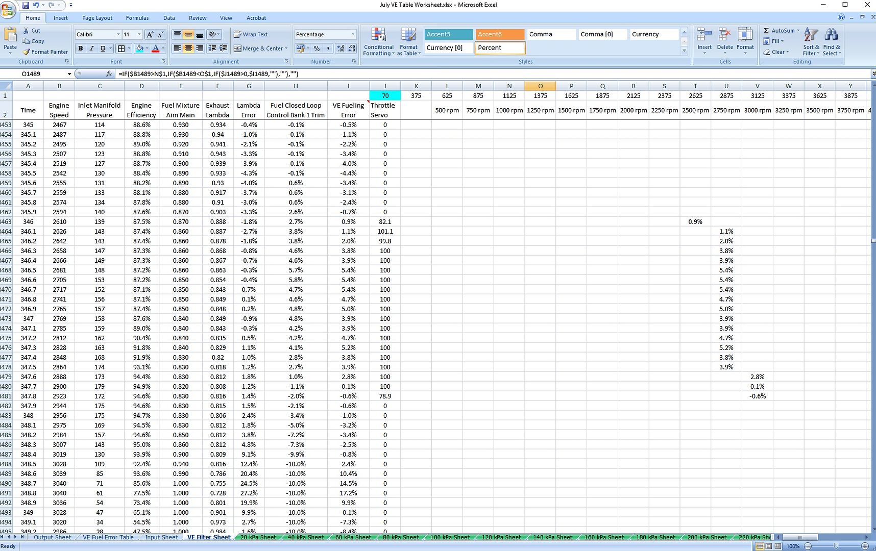
A filter sheet then sorts the data I want to look at into columns:
The turquoise cell showing a "70" is a throttle filter that I apply. Throttle positions over the value in that cell are counted, and then used to filter the fuelling data. This gives me the ability to look at only WOT data, part throttle, or tip-in response at lower engine speeds.
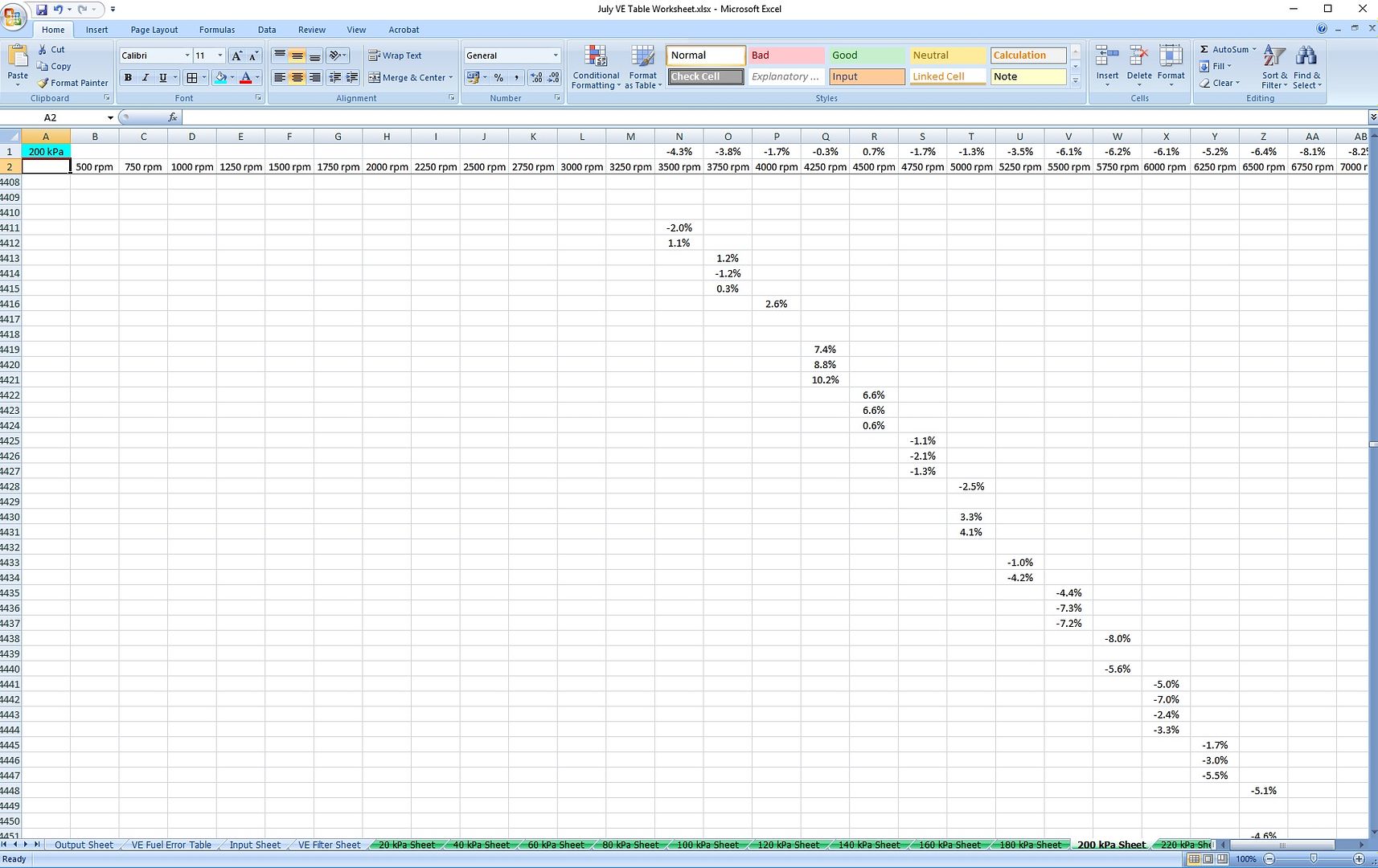
Each load point on my VE table has it's own sheet, so that I can average the closed loop errors into RPM columns. Below is the 200 kPa sheet, where you can see a full throttle pull across various RPM points:
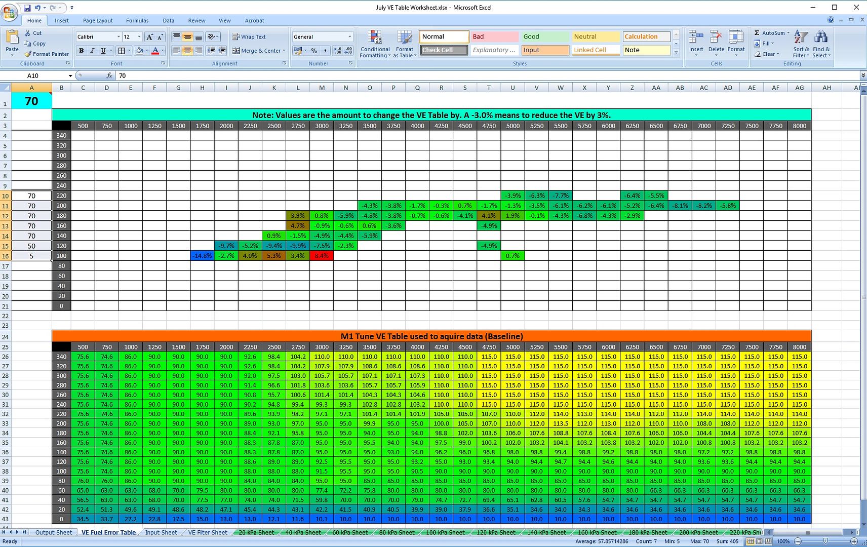
Using all of the VE load point sheets, I'm able to build a correction map:
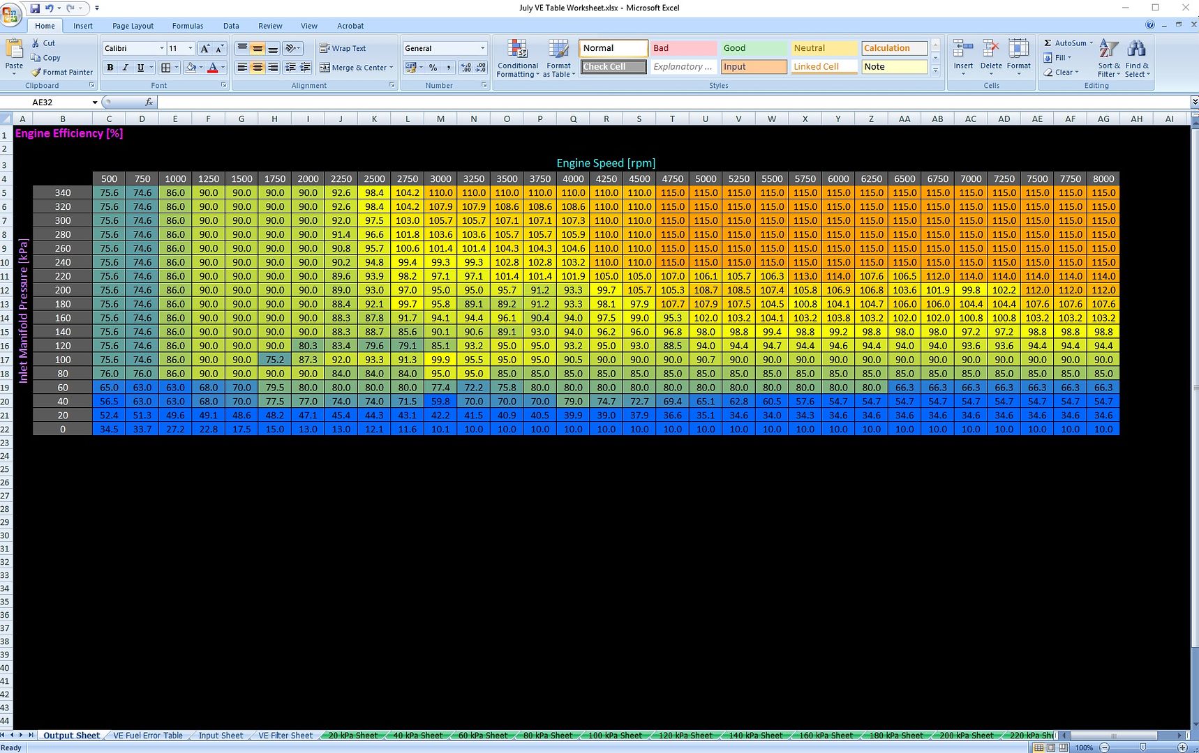
And if I want, I can copy and paste from the sheet shown below directly into M1 Tune:
The above process allows me to drive the car around, generating closed loop correction values, and easily adjust the VE table to reduce the closed loop compensation. In the event that my Lambda sensor fails, I should have a feed forward VE table that works.....
Lead Disagreement Eng PE
Sounds very... data analysis intensive.
Create a new channel that calculates the feedback amount, and multiplies it by the current VE value. Then you've got an easy to reference "newVE" value that you can look at the maps at WOT areas that aren't significantly affected by throttle rate fueling, and then plug that in. Cleans things up pretty quickly after a few WOT pulls and some cruising areas at in between MAP values.
Member
Was thinking the same thing... so much work for something that should be arguably very, very simple.
M54B30 Inside
I tried that before creating the method I described above. It is fairly useful for WOT, but that represents a very low % of the engine's operating conditions. I wanted to see if I could get useful data for part throttle loads, and that lead me to this. In reality, there are too many other variables involved with part throttle to get highly accurate results, but I wanted to try.....
Where's the fun in keeping it simple?
- - - Updated - - -
BTW....looking to install a wastegate position sensor on the MVR....so we can see what the SS TS manifold is really doing.
Lead Disagreement Eng PE
That's why you disable all TPSdot enrichment, or at least keep it conservative, and then go out and do some steady state pulls at various boost levels. Essentially you start a pull at say 100 kpa and pull through some amount of the rev band, do the same trying to stay around 120 kpa, 140 kpa, 160, 180 kpa, etc. Then do a full boost pull.
Then you find on your logs where you're doing a pull and not influenced by TPSdot effects (AFR will likely be a tad wonky tipping in with somewhat off TPSdot enrichment), and look at the sweeps and tweak VE values. It should follow a fairly predictable pattern at different boost pressures, but if you have some turbine restriction or something like that, you'll see the higher RPM, higher boost pulls show the VE slacking off vs. the lower boost stuff.
Go through, make some changes to get closer, then work on enrichment. Make a few different throttle rate stabs at idle, 2k rpm, 3k rpm, 4k rpm etc. Tweak that table. Should be pretty close. Do another boost sweep through the rev range, make changes. Should be pretty well dialed in at this point, but you can always do a future sweep.
It really doesn't take very long as long as you're willing to spend some time getting some logs, then making adjustments, then make some more pulls, dial it in some more.
Member
Should be very interesting. Have you been logging turbine speed at all?
Member
Is it selfish of me to wish an S54 upon you so we could drown ourselves with copious amounts of data? I'd get an M1 if you got an S54... :P >>Edge>>Push
1000+RWHP, Lab22 Built Turbo S54 - BMW Half Mile Record Holder
M54B30 Inside
In 2013 I had turbine speed using the Garrett dash gauge. When I converted to the Motec, I connected the sensor directly to the ECU and haven't been able to get it to read a signal. In all honesty, I think I might have damaged the sensor, so I forked over another $350 to Joel @ race spec, and he shipped me another sensor kit in June. That is now likely to be installed on the GTX40 compressor housing.....
Buy my M54 inventory, and I'll convert to S54.
In reality, I need someone to ship this stuff to more than I need to make a buck....so low-ball offers would be entertained.
I can see Julio's ears perked up in Florida....
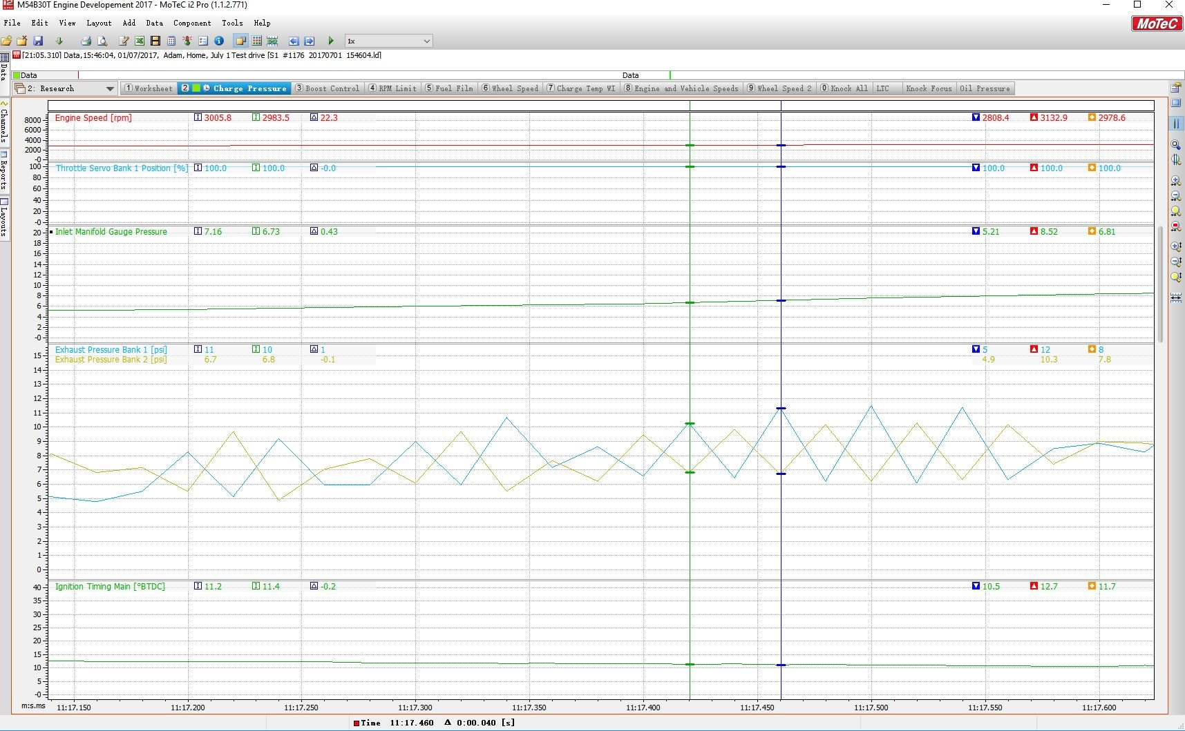
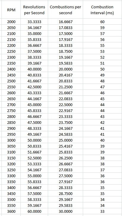
And here's my interesting data post for today:
Yup...I can see individual exhaust pulses in the twin scroll manifold! The logging rate is only 50 Hz, so I lose resolution at higher engine speeds. I've since revised the sample rate to 200 Hz so I can follow this at higher RPMs.
Lurker
BMW CCA Member
My thought exactly!
Member
Wowzah! Impressive...
Now the people have spoken...S54 time
1000+RWHP, Lab22 Built Turbo S54 - BMW Half Mile Record Holder
Member
Something to pick your brain on too...affect of Exhaust back pressure on vanos. For a single gear pull it's not required but when you have several gears and ebp is already high from 3rd through 5th I suspect there is some power to be gained. I think a basic trim table would be good for that testing. Also similar to how the new bmw's do it...a spool mode for other vanos mapping... man I wish I could build my own custom tables.
Last edited by Commanderwiggin; 07-21-2017 at 12:06 PM.
1000+RWHP, Lab22 Built Turbo S54 - BMW Half Mile Record Holder
M54B30 Inside
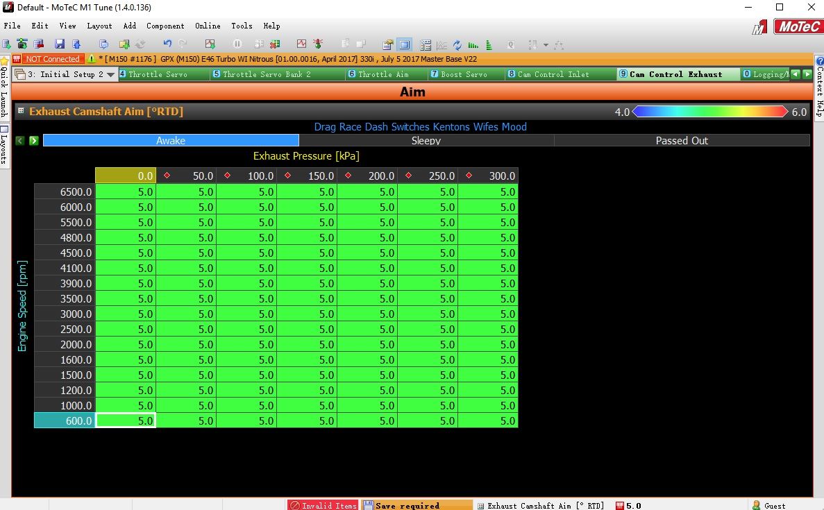
If you troll me on the S54, I'll troll you on the M1:
Luchador
Nice. P3 based exhaust cam phasing.
M54B30 Inside
In reality, using exhaust pressure would kind of be a circular dependency. Using inlet manifold pressure, and knowing what the exhaust side was doing would be more ideal.
The switch position is an inside joke....
Currently working on an automated launch system involving 3 additional solenoids and a proportioning valve. The logic functions are doing my head in...
Member
Hahaha yes!!! I need that dash switch! In reality I scared the wife with the new turbo since it pulls to the moon (6870 would start to fall on its face)...she won't ever fall asleep in it again (if she ever gets in it again).
Secondly...you bast@rd. I need an M1 now.
Last edited by Commanderwiggin; 07-22-2017 at 09:03 AM.
1000+RWHP, Lab22 Built Turbo S54 - BMW Half Mile Record Holder
Luchador
P3 is usually a correction factor for VGT position/exhaust cam phase to match the target pressure. I assumed thats what you were doing. Based on RPM and P3 you would know what to move the exhaust cam phase to. At that point it could make another evaluation and adjust. Probably want a slew on cam phase adjustment rate so you don't overshoot.
There is no point in estimating P3 if you can directly measure what the value actually is. Never guess when you can calculate, never calculate when you can measure!
Last edited by wazzu70; 07-22-2017 at 12:26 PM.
u owe my mule an apology
Without a maf it would be a nightmare trying to get the fueling right when using that sort of targeting for the cam timing
86 325es, 2.8L m50, S476sxe, ProEFI 128 ecu, e85, solid rear axle, TH400 trans, 28x10.5w slicks, zip ties, popsicle sticks, tape
best time 9.06 @ 151.8 mph, best 60 foot 1.30
Lead Disagreement Eng PE
Is there really much in it for a variable amount of exh cam phasing related to EBP? I can only see that affecting things during the spool up phase, then it should be steady state once the WG opens. Doesn't matter for 1 gear or 2, 3 etc. pulls, it'll go steady state very quickly from the perspective of the engine/control sys.
I could also see wanting a different amount of phasing for just cruising, spool up, then steady state in boost. But again, probably not a lot in it really...
Luchador
The biggest gain I could see would be for spoolup. You are right, probably not huge gains but its fun to experiment with.
M54B30 Inside
Need dyno.
M54B30 Inside
I'm very excited to be sharing this next bit of data. While I've had a Motec PDM in the car for over 2 years, I haven't really shown it.
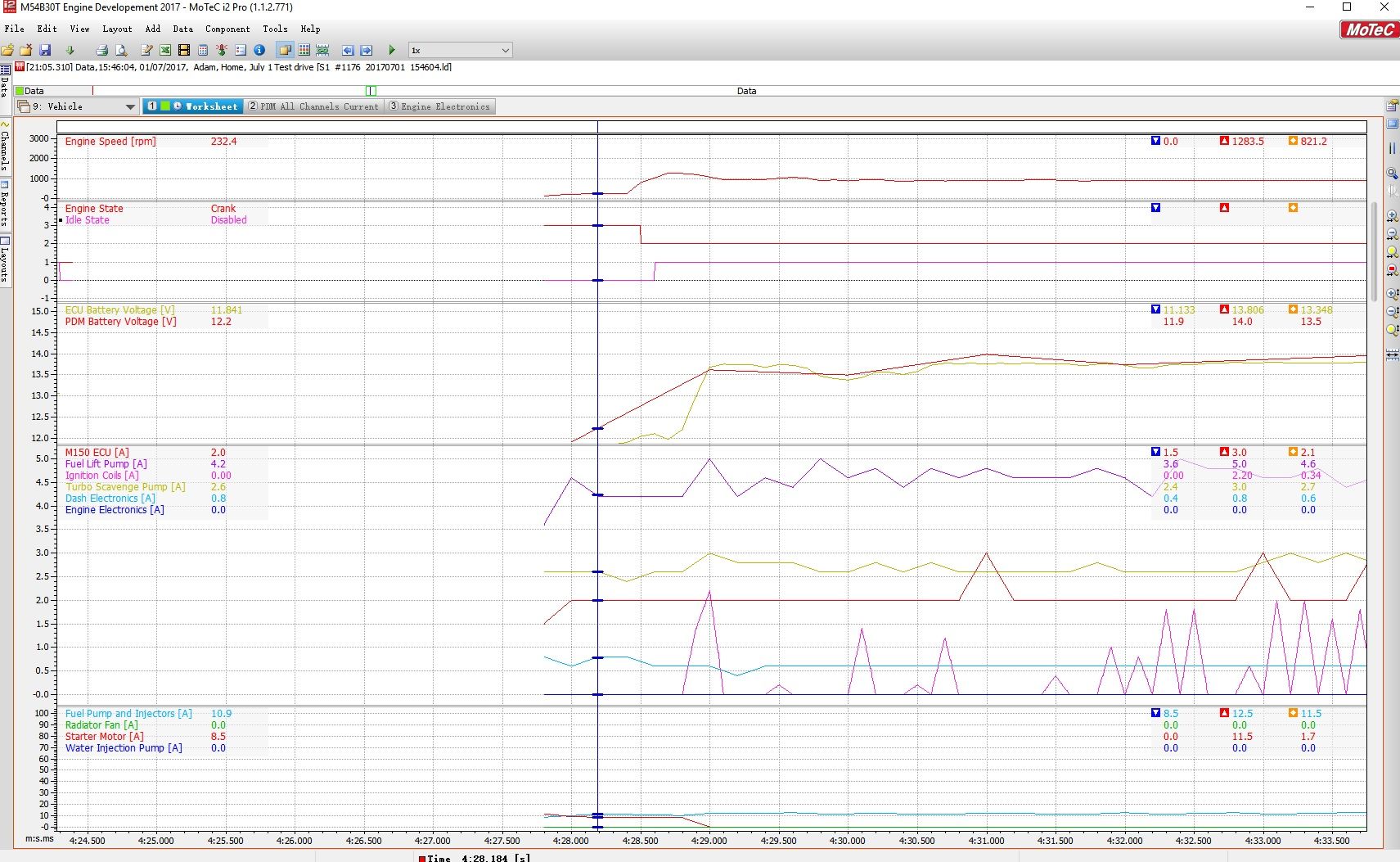
This is what starting the car looks like:
The starter motor pulls about 12amps when it activates, then settles down to about 9 amps during cranking.
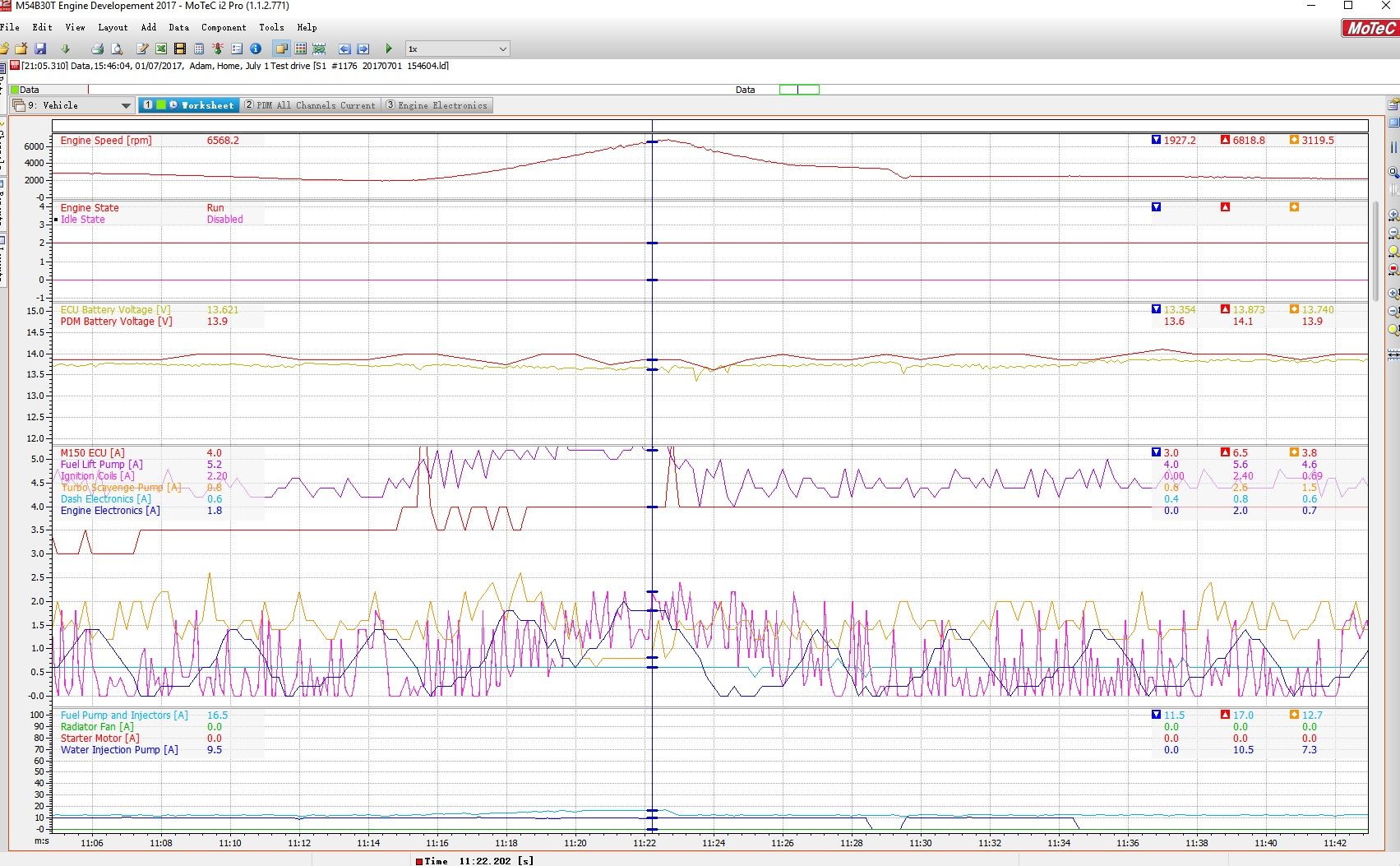
This is the engine under load:
The ignition coils pull about 2 Amps....which surprised me. (I thought it would be more) At idle, the coils pull so little current that I had to employ 2 decimal places in the data trace.
The lift pump (OEM Fuel pump), which feeds the A750 inline pump, normally pulls about 4 amps at idle and light load. As fuel pressure is increased in reference to manifold pressure, we see 5 amps of load.
The A750 inline pump, which is on the same circuit as the injectors, pulls about 12 amps at idle. In the example above, we see load increase to over 16 amps as RPM and manifold pressure increases.
The Aquamist water injection pump is running, pulling about 10 amps.
There were 2 surprises looking at the PDM data. The first is that the scavenge pump pulls about 3 amps when the engine starts, but when the engine is warmed up, its under 1 amp of draw. The second surprise came from the Engine Electronics circuit, which feeds the Lambda sensor, TC8 thermocouple input, E888 I/O expander, and the boost control solenoids. It oscillates between 0.1 to 1.8 amps, and I don't know why. Sure, most of you will say to check X or Y for correlation, but none of it lines up. The heater circuit duty cycle on the Lambda sensor I am logging, and it doesn't match up. The boost control solenoids don't match up. At some point, I'm going to disconnect indidual devices, and see what the mystery is...but for now...nothing is wrong...it's just interesting.
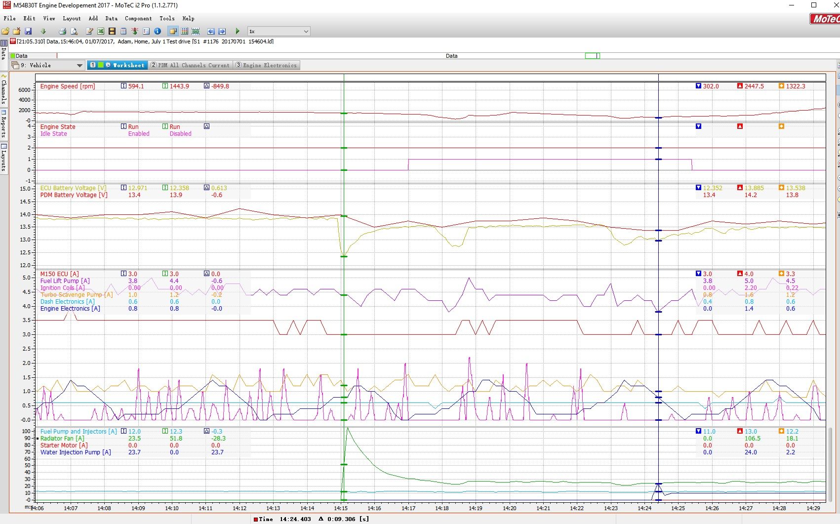
And here's the monster of current consumption, the radiator fan being activated:
106 amps peak draw, settling down to about 24 amps continuous. This caused me quite a few problems initially, where I only had the fan on one 20 amp output. I've since bridged 2 of them together, and everything works fine now. The OEM controller, which I removed, uses a PWM signal to gradually increase fan speed, so you won't see this kind of draw on most of your cars.
Also of note, is the activation of the WI pump with 24 amps peak current draw.
M54B30 Inside
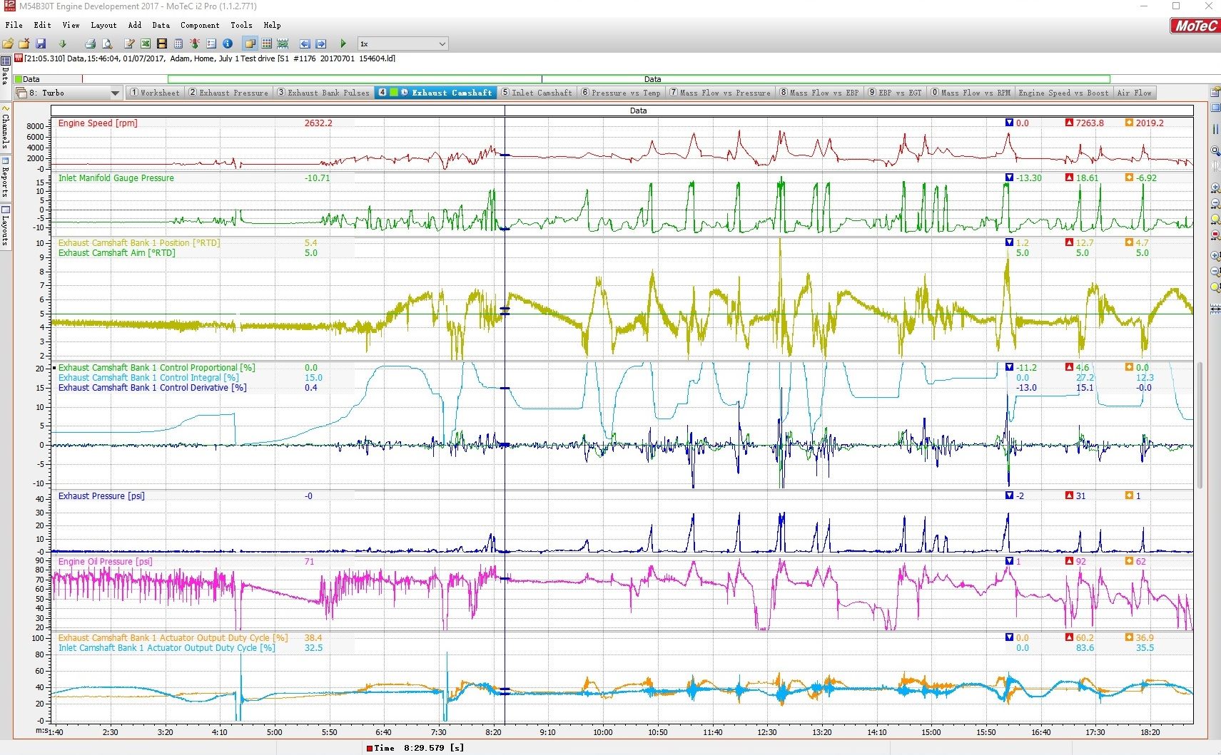
Seems I've got too much Integral, and a poor feed forward on the VANOS:
Luchador
At least you can log so you know where to improve instead of just guessing...
M54B30 Inside
Well...that's half the battle.
A lot of times stuff is there staring me in the face, and I don't recognize what the data is telling me. LOL
In this case, the feed forward value (which I forgot to log, but it is a static value) is 30%, and it really needs to be less than that. For the intake cam, which I haven't shown, it's not too far off. But for the exhaust cam, it's off a lot! I've changed the settings so that there is ZERO integral gain, and will try 19% on the exhaust cam to see if it will hold position. From there, I'll need to setup the tables for oil temp, because the system will respond differently to cold oil vs warm oil. (It's easiest to set up the tables with warm oil first, so see what works in stead state)
I never thought tuning the VANOS was going to be this involved....but here we are. I guess the difference between what I'm doing, and most other engines on here, is that the M52/S52 is on/off where the M54 is PWM. (continuously variable)
Curtesy of Robert Jansson:
M50tu = Single VANOS (on/off) - 1 solenoid I/O
M52 = Single VANOS (on/off) - 1 solenoid I/O
M52tu = Double VANOS (Infinitely variable) - 2 solenoid pwm
M54 = Double VANOS (Infinitely variable) - 2 solenoid pwm
N52 = Double VANOS (Infinitely variable) - 2 solenoid pwm
("M" Engine)
S50 = Single VANOS (Infinitely variable) 1992-1994 not in u.s - 2 solenoid pwm
S50 = Double VANOS (Infinitely variable) 1995-1998 not in u.s - 4 solenoid pwm
S52 = Single VANOS (on/off) 1996-1998 u.s - 1 solenoid I/O
S54 = Double VANOS (Infinitely variable) - 4 solenoid pwm
8cyl.
M62tu = Single VANOS (Infinitely variable) - 2 solenoid pwm
N62 = Double VANOS (Infinitely variable) - 4 solenoid pwm
("M" engine)
S62 = Double VANOS (Infinitely variable) - 8 solenoid pwm + 1 pwm solenoid pressure regulator
S85 = Double VANOS (Infinitely variable) - 4 solenoid pwm + 1 pwm pressure regulator
12cyl.
N73 = Double VANOS (Infinitely variable) - 4 solenoid pwm
Note: The engines starting with an "N" also have valvetronic variable intake valve opening, you would require extra outputs to drive the valvetronic adjusting motors and inputs for valve position feedback. Valve lift can be varied anywhere from 0.3 to 11mm.
 Posting Permissions


 Reply With Quote
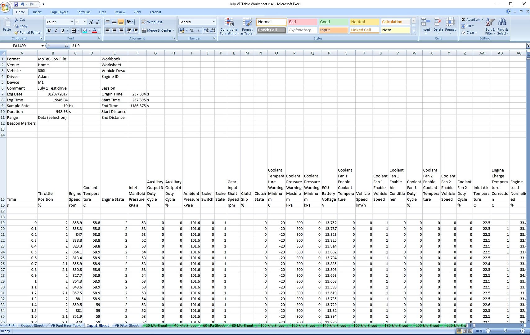


Bookmarks