
 Member
I was changing my injectors and I saw something that doesn't make sense, Ok I will try to explain this as simple as possible.
Coming out of the wire harness conduit, towards the front of the engine that houses the injector and sensor wires, there are 4 sets of wires for the CI and CPS (2 per side). What I am seeing is 1 black and 1 gray plug per side, 1 for CI and 1 for CPS. In the mounting brackets both the gray plugs are at the bottom and the blacks ones are on top on both sides.
On the RIGHT side the CI is plugged into the BLACK plug (TOP) and the CPS is plugged into the GRAY plug (BOTTOM).
On the LEFT side the CI is plugged into the GRAY plug (BOTTOM) and the CPS is plugged into the BLACK plug (TOP).
Now I know they are supposed to be "crisscrossed/opposite" (CI on TOP on one side and on BOTTOM on other vice versa for the CPSs) of each other BUT shouldn't both the CIs and CPSs be plugged into the same color plug?
If they were plugged in incorrectly would the car even run? I do get CO2 and Lamda sensor stomp codes could this explain my stomp code errors?
Advice???
Last edited by DV8OR; 06-21-2014 at 07:41 PM.
OO=[][]=OO
BMW CCA First Coast Chapter
Vice-President
BMW CCA Foundation Ambassador
"You cannot expect to wield supreme executive power just 'cause some watery tart threw a sword at you?"
shade tree mechanic
Moderator
Last edited by shogun; 12-10-2019 at 10:32 PM. Reason: updated
Shogun tricks and tips for the E32 series are HERE!
Member
Thank you Shogun but I have diagrams (but they don't show plug color). So my main question is shouldn't they, the CIs or CPS, be plugged into the same color plug? Since the plugs had to be taken out of the brackets to be able to flip the wire harness up and out of the way, they could have been put back incorrectly.
Should both gray plugs be on the bottom and both black plugs be at the top?
Would the car run if they were plugged in incorrectly?
OO=[][]=OO
BMW CCA First Coast Chapter
Vice-President
BMW CCA Foundation Ambassador
"You cannot expect to wield supreme executive power just 'cause some watery tart threw a sword at you?"
Member
without the cps plugged in right it wont run. the other two it still ran without them plugged in.
heres what mine look like. I used a mutlimeter to find which wires went where
Last edited by me78569; 09-05-2017 at 11:41 AM.
Member
TYVM !!! that is what I needed
OO=[][]=OO
BMW CCA First Coast Chapter
Vice-President
BMW CCA Foundation Ambassador
"You cannot expect to wield supreme executive power just 'cause some watery tart threw a sword at you?"
shade tree mechanic
Moderator
That is a good find, thanks for the pic, me78569.
Maybe you explain clearly what goes where, left top and right bottom should be the crankshaft position sensors according to the shop manual. But even the Bentley repair manual shows different info. So as per your pic it would be probably left top black, right low white?
here is a good pics (forget about the 2 red arrows, that is for the breather pirpe) which shows the colors of the plugs and where the wires go, the 2 going down are for the CPS and the other 2 are for the donuts http://www.bimmerboard.com/members/t...eatherpipe.jpg
Last edited by shogun; 03-02-2022 at 09:22 AM.
Shogun tricks and tips for the E32 series are HERE!
Member
Just out of curiosity I would be interested in which plugs each sensor is plugged into. For instance is LEFT side gray plug is CPS and black CI.
OO=[][]=OO
BMW CCA First Coast Chapter
Vice-President
BMW CCA Foundation Ambassador
"You cannot expect to wield supreme executive power just 'cause some watery tart threw a sword at you?"
Member
I would love to tell you and I was going to look at it closer to tell you exactly, but I ran out of time, because I was wet sanding the car and couldn't stop haha.
I will try to get to this tomorrow for you.
Member
That would be awesome ty
Last edited by shogun; 04-19-2015 at 12:35 AM.
OO=[][]=OO
BMW CCA First Coast Chapter
Vice-President
BMW CCA Foundation Ambassador
"You cannot expect to wield supreme executive power just 'cause some watery tart threw a sword at you?"
Member
alright I had some time to run out and look. Excuse my lack of "terms"
But here is what I found
8fb58e31-d625-4c83-882c-2c60c825a9fb_zpse12f1a7d.JPG
Drivers black plug goes to the "Spark sense wire" ( unsure of the technical name for that)
Drivers Grey plug goes to the drivers crank position sensor
Pass Grey plug goes to the pass side "spark sense wire"
Pass black wire goes to the pass crank position sensor.
Shogun does that sound right? I new it was odd that one sides color didn't match the other side, but my runs without codes in this config.
- - - Updated - - -
http://www.realoem.com/bmw/enUS/showparts?id=GC83-USA-10-1989-E32-BMW-750iL&diagId=12_1608
Drivers side black goes to #7 pulse generator
Pass side grey does to #7 pulse generator
http://www.realoem.com/bmw/enUS/show...diagId=12_1584
Drivers grey goes to the crank position #14
Pass black goes to the other crank position, which is not shown in above image, not sure why not.
Last edited by me78569; 09-05-2017 at 11:42 AM.
Member
Yup that looks right.
I was trying to confirm whether or not the CIs or CPSs should be plugged into the same color plugs but you confirmed that they are not.
Thank you very much
OO=[][]=OO
BMW CCA First Coast Chapter
Vice-President
BMW CCA Foundation Ambassador
"You cannot expect to wield supreme executive power just 'cause some watery tart threw a sword at you?"
shade tree mechanic
Moderator
As you have no fault codes, it should be like you say. Spark sensor = pulse generator aka donut.
Let's see what DV80R finds out with measuring after he read your info, and if that is confirmed, please make a final version of this pics with the correct 'terms', there is always confusion what is for what.
We already have learned that there are white and black plugs.
Question is of course how one can avoid misconnections if he had all the ignition wires and these plugs out and does not remember exactly which plug in which colour goes where?
Shogun tricks and tips for the E32 series are HERE!
Member
Looks like he says it is working.
I will get something put together later, life's busy so I cannot promise it will happen tonight haha.
as for avoiding issues in the future that is a good question, really the saving grace is the wires going to the computer in the engine valley are old enough now that they keep their shape
Member
My notes show differently than me's but I cant go check right now. I will post up as soon as I can check.
FYI if my notes are correct, i did write them very quickly, mine are opposite of me's.
me's
Drivers
CI TOP Black plug
CPS BOTTOM Gray Plug
Passenger
CPS TOP Black plug
CI BOTTOM Gray plug
Mine
Drivers
CPS TOP Black plug
CI BOTTOM Gray plug
Passenger
CPS BOTTOM Gray plug
CI TOP Black plug
I will check shortly and let you know
ME78569
What year is your 750il, I notice you don't have the oil fill above the plugs so I am assuming a pre 92. I don't remember anything in the Bentley manual about it being different year to year.
- - - Updated - - -
Ok I double checked and my notes were wrong
Mine as is
Driver
CI TOP BLACK
CPS BOTTOM GRAY
Passenger
CPS TOP BLACK
CI BOTTOM GRAY
Sorry for the confusion but you did confirm that the same sensors are plugged into different color plugs on each side.
TYVM
OO=[][]=OO
BMW CCA First Coast Chapter
Vice-President
BMW CCA Foundation Ambassador
"You cannot expect to wield supreme executive power just 'cause some watery tart threw a sword at you?"
Member
Yep no prob
shade tree mechanic
Moderator
To have it all complete, here by Timm: BMW E32 E38 M70 M73 V12 ENGINE DISTRIBUTOR LEAD ORDER
http://www.meeknet.co.uk/E32/V12_Distributor_Leads.htm
Hope that this is o.k., if someone notices something wrong, please correct us.
Shogun tricks and tips for the E32 series are HERE!
shade tree mechanic
Moderator
crankshaft position sensor testing
updated by Bentley Publishers especially for the M60 engine, before there was 1200 Ohm mentioned by mistake
Ignition Coil Resistance (M60 engine) Terminals Resistance
Coil primary 1 (–) and 15 (+) 0.8 Ω (approx.)
Using digital multimeter, check resistance between terminals
1 and 2 in crankshaft position/rpm sensor connector.
Crankshaft Position/rpm Sensor Specifications
• Coil resistance (approx.) @ 20°C . . . . . . 540 ± 10% Ω
• Air gap (sensor distance from
toothed wheel) . . . . . . . 1.0 ± 0.3 mm (0.04 ± 0.01 in.)
https://wiki.bentleypublishers.com/d...=1306522675840
M30/M70 ignition system data accdg to Bentley
Coil primary, coil code # 2051118335 terminals 1 (-) and 15 (+) resistance 0.50 ohm, Coil primary, coil code # 20510171101 terminals 1 (-) and 15 (+) resistance 0.37 ohm
Coil secondary, coil code # 2051118335 terminals 15 (+) and 4 (ctr. resistance 6.0 kohm, Coil secondary, coil code # 20510171101 terminals 15 (+) and 4 (ctr. resistance 9.0 kohm
spark plug ends 5.0+/- 10% kohm, shielded plugs 1.0 +/- 20% kohm, spark plug wires 0 ohm (approx.), rotor 1.1 +/- 10% kohm
M70 firing order: 1-7-5-11-3-9-6-12-2-8-4-10, crankshaft position/rpm sensor: 540+/- 10% ohm
from workshop manual
distributor rotor 1+/-20% kohm, angled/shielded connectors 1+/- 20% kohm, spark plug connectors 5+/- 20% kohm, cylinder identification sender coil resistance at 20 degree C (68F) <1 ohm, pulse sender/crankshaft position sensor coil resistance 540 +/- 10% ohm, temperature switch for e-box cooling E32 750: switch on at 44 +/- 3 degree C, switch off at 36 +/- 3 degree C.
Last edited by shogun; 10-08-2020 at 10:41 PM.
Shogun tricks and tips for the E32 series are HERE!
shade tree mechanic
Moderator
Inductive and Hall Effect crankshaft position sensor Explained
It is often said a good CPS should have 550 +/- 10% ohm and it could be measured with an ohmmeter. This is NOT always the case, the question is if the CPS is a inductive or hall CPS. Hall CPS checking is completely different, there the volts are checked.
Here is a long thread where you can see the confusion where someone tried on an E36 EURO version to check with an ohmmeter a hall sensor (he did not know it was a hall sensor)
Crank Sensor Dying Every Year http://www.bimmerforums.com/forum/sh...ing-Every-Year
Inductive and Hall Effect crankshaft position sensor Explained https://www.linkedin.com/pulse/induc...kiril-mucevski
Inductive and Hall Effect RPM sensors in today’s vehicles, mainly are used for measuring the rpm and determining the position of crankshaft or camshaft at engine management systems, as well as measuring the speed (rpm) of the wheels at ABS systems, ESP systems, etc.
The RPM sensors typically can be Hall or inductive type. The operation of these sensors is fundamentally similar in all instances, although the construction can vary depending on the type of sensor, its intended use or manufacturer application.
Inductive Sensor Operating Principles and Specification
The inductive sensor, also known as magnetic pickup sensor, during the operational work, as result of inductive effect, in the sensor’s coil is producing the oscillating voltage, i.e. one kind of sinusoidal waveform signal (∼ AC voltage).
When the trigger wheel with the teeth passes in enough close distance (G) to the pole pin of the sensor, the magnetic field surrounding the coil is changed. As the result of the magnetic field changes, in the coil a voltage is induced, which is proportional to the strength and rate of change of the magnetic field. One complete oscillation is produced for each tooth that passes beside to the sensor pole pin. Figure 1 shows the basic integral components and the shape of the generated signal of an inductive sensor.
Figure 1. Inductive sensor:
1. Sensor housing, 2. Output signal wires, 3. Coaxial coated protection
4. Permanent magnet, 5. Inductive coil, 6. Pole pin,
7. Trigger wheel, G. Air gap
Depending upon the manufacturer application and type of the sensor, the electrical resistance of the coil is typically in the range between 500 ohms and 1.500 ohms. In some extreme cases, the lowest value can be about 200 ohms, as well as in some cases, the highest value can be up to 2.500 ohms.
The voltage signal produced by the sensor depends on the speed of the trigger wheel and the number of turns in the coil, so an output voltage could be expected between 1V and 2V during the engine cranking for example, but in cases at higher rpm, can expected more. The output voltage signal produced by the sensor is weak, i.e. low energy level, so could easily be degraded by other external stronger signals, such as the ignition system for example. For that reason, to eliminate the external influences, the signal wires from the sensor to the control unit are usually shielded with a coaxial coated wires type of protection.
Hall Effect Sensor Operating Principles and Specification
Unlike inductive sensors, the output signal from a Hall effect sensor is not effected by the rate of change of the magnetic field. The produced output voltage typically is in the range of milli volts (mV) and is additionally amplified by integrated electronics, fitted inside of the sensor housing.
Figure 2 shows a typical build of a Hall Effect sensor. The final output voltage signal usually is in digital waveform pulses (square form). The output signal of the sensor can be either positive or negative with peak voltage usually up to 5 V or 12 V, depending upon the type of the integrated electronics and requirements of the used system. The amplitude of the output signal remains constant, only the frequency increases proportionally with rpm. Unlike inductive sensors which generate a voltage signal by itself, the Hall Effect sensors must be additionally supplied by external voltage needed for integrated electronics. The usual supplying voltage (+Vcc) is mainly 5 V but in some cases can be 12 V.
Figure 2. Hall Effect sensor: 1. Sensor housing, 2. Output wires (+Vcc, −Vcc and signal),3. Integrated electronics, 4. Permanent magnet,5. Hall Effect device, 6. Trigger wheel, G. Air gap
Inductive Sensor Diagnostics and Testing Procedures
• Unplug the sensor and check that the electrical resistance of the inductive coil is roughly between 500 ohms and 1.500 ohms. If the reading value is drastically different, including zero or infinite, replace the sensor.
NOTE: In some extreme cases, the lowest resistance can be about 200 ohms, as well as in some cases, the highest resistance can be up to 2.500 ohms.
• Check the size of the air gap (G) between the sensor and the trigger wheel, the value should be: G ≈ 0.8 – 1.5 mm (0.03 – 0.06 inch).
• Check the cleanliness of the sensor pin (sometimes may have cumulated metal turnings).
• Check the continuity and condition of the wires, connectors, terminals and the condition of the shielding.
• Unplug the sensor and check that there is an output AC voltage when cranking the engine (for engine rpm sensors) or when a wheel is rotated (for ABS wheel sensors). The output voltage signal could be expected between 1 V and 2 V (∼AC voltage) during the engine cranking for example, but in cases at higher rpm, can expected more. Also, this operation can be performed and when the connector of the sensor is plugged in.
Hall Effect Sensor Diagnostics and Testing Procedures
• Check the power supply to the sensor. The usual supplying voltage is 5 V (in some cases can be 12 V).
• Check the size of the air gap (G) between the sensor and the trigger wheel, the value should be: G ≈ 0.8 – 1.5 mm (0.03 – 0.06 inch).
• Check the continuity and condition of the wires, connectors and terminals.
• Check the cleanliness of the sensor pin (sometimes may have cumulated metal turnings).
• Check that there is an output signal when cranking the engine (for engine rpm sensors) or when a wheel is rotated (for ABS wheel sensors).
NOTE: Unlike inductive sensors, at Hall sensors the connector must be plugged in, because is needed power supply for integrated electronic components, which are inside of the sensor.
For testing can be used: test LED lamp, electrical multimeter or oscilloscope. When is used test LED lamp, during the engine cranking, the LED should fast blinking according to the engine rpm, but in cases at higher rpm, the blinking is difficult to be follow. Then is better to use multimeter or oscilloscope for check the frequency as well as voltage of the signal.
Important advice: When testing the signal of a sensor, never use a test lamp with tungsten filament, may cause an extra current overload and produce damage of the sensor. It is recommended always to use some of the more sensitive tools, like test lamp with LED light or electrical multimeter for example.
Hella says (unfortunately only in German, so you have to copy and translate page 22, 23) that measuring ohm on a hall sensor can destroy the sensor http://markus.tizara.de/docs/Elektro...nics_Part1.pdf
excerpt:
Kurbelwellensensoren haben die Aufgabe, die Drehzahl und die Kurbelwellenposition zu ermitteln. Sie werden am häufigsten in der Nähe des Schwungrads an einem Zahnkranz eingebaut. Es gibt zwei Bauarten:
Induktivgeber und Hallgeber.
Vor einer Kurbelwellensensor-Prüfung muss unbedingt ermittelt werden, um welche Art von Geber es sich handelt. Die Drehbewegung des Zahnkranzes bewirkt Magnetfeldänderungen. Die von den Magnetfeldern erzeugten unterschiedlichen Spannungssignale werden an das Steuergerät geleitet. Aus den Signalen errechnet das Steuergerät Drehzahl und Position der Kurbelwelle, um wichtige Grunddaten für die Einspritzung und Zündverstellung zu erhalten. Bei einem Ausfall des Kurbelwellensensors können folgende Fehlersymptome auftreten:
■ Aussetzen des Motors
■ Motorstillstand
■ Abspeichern eines Fehlercodes
Ausfallursachen können sein:
■ Innere Kurzschlüsse
■ Leitungsunterbrechungen
■ Leitungskurzschluss
■ Mechanische Beschädigungen des Geberrades
■ Verschmutzungen durch Metallabrieb
■ Auslesen des Fehlerspeichers
■ Elektrische Anschlüsse der Sensorleitungen, des Steckers und des Sensors auf richtige Verbindung, Bruch und Korrosion prüfen
■ Auf Verschmutzung und Beschädigung achten
Die direkte Überprüfung des Kurbelwellensensors kann schwierig werden, wenn man nicht die genaue Bauart des Sensors kennt. Vor der Prüfung muss geklärt werden, ob es sich um einen Induktiv oder Hallgeber handelt. Die beiden lassen sich optisch nicht immer voneinander unterscheiden. Bei einer Steckerpinanzahl von drei lassen sich keine genauen Aussagen über den jeweiligen Typ treffen. Hier helfen die spezifischen Herstellerangaben und die Angaben im Ersatzteilkatalog weiter.
Solange die Bauart nicht eindeutig geklärt ist, darf kein Ohmmeter für die Überprüfung benutzt werden. Es könnte einen Hallgeber zerstören! Besitzt der Sensor einen 2-poligen Stecker, handelt es sich vorrangig um einen Induktivgeber. Hier können der Innenwiderstand, ein eventueller Masseschluss und das Signal ermittelt werden. Dazu entfernt man die Steckverbindung und prüft den Innenwiderstand des Sensors. Beträgt der Innenwiderstandswert 200 bis 1.000 Ohm (je nach Sollwert), ist der Sensor in Ordnung. Bei 0 Ohm liegt ein Kurzschluss und bei M Ohm eine Unterbrechung vor. Die Masseschlussprüfung erfolgt mit dem Ohmmeter von einem Anschlusspin zur Fahrzeugmasse. Der Widerstandswert muss gegen unendlich tendieren. Die Überprüfung mit einem Oszilloskop muss ein Sinussignal in ausreichender Stärke ergeben. Bei einem Hallgeber sind lediglich die Signalspannung in Form eines Rechtecksignals und die Versorgungsspannung zu überprüfen. Es muss sich in Abhängigkeit von der Motordrehzahl ein Rechtecksignal ergeben. Es sei noch einmal gesagt: Der Einsatz eines Ohmmeters kann den Hallgeber zerstören.
Shogun tricks and tips for the E32 series are HERE!
shade tree mechanic
Moderator
Comment on the German forum:
Die Einbaurichtung ergibt sich durch die Bauform des Donut. Die Bohrung ist innen leicht konisch und geht auf der Seite, an dem man die kleinen 3 Nasen sieht zusammen und geht von der Seite aus nicht auf das Zuendkabel. Somit ist dann die Seite mit den kleinen Nasen in Richtung Verteiler und die offenere Seite mit dem Radius in Richtung Zuendkerze.
translated:
The installation direction is determined by the shape of the donut. The bore is slightly conical on the inside and get's on the side, where the small 3 noses are located smaller in diameter and will not fit from this side onto the ignition wire. Thus, the side with the small lugs should be in the direction of the distributor and the more open side with the radius in the direction of the spark plug.
see here also the pics from Sean which is converting a M30 wire set for a M70
http://bmwe32.masscom.net/sean750/Re...rkPlugBoot.jpg
http://bmwe32.masscom.net/sean750/Re...ireSet_V12.htm
Last edited by shogun; 12-10-2019 at 10:12 PM.
Shogun tricks and tips for the E32 series are HERE!
shade tree mechanic
Moderator
For info copied from another thread: I just read in the German forum about a case where someone changed on his M70 distributors, rotors, spark plugs and ignition wires on cyl. 6 and 12 and used the re-old donuts. Then he had trouble. Engine starts, runs short time with increased RPM and then dies. EML lamp goes on with ignition on and then goes out again as it should be. Diagnosis faults: fault ignition cylinder 1-6 and 7-12. That was 2 weeks ago. Today he fixed it. He noticed that he installed the cylinder identification sensors/donuts/pulse generators on ignition wires cyl. 6 and 12 the wrong way. Turned the donuts the correct way and engine runs smooth.
original Pulse generator 12121725020 pic https://www.ecstuning.com/b-genuine-...e/12121725020/ So make sure the donuts are working and installed the correct way.
------------
DV8OR comment: I will go check but if I remember correctly the OE BMW one are symmetrical and I did not see any type of mark as to direction. The aftermarket one that I had was larger on one side like the pic you posted but if you are having issue it might be worth a try to flip it.
-----------------------
my reply: no marks on the original ones, if I remember correct.
Aftermarket pics based on this website info
Facet 9.0103 https://boodmo.com/catalog/part-sens...ssion-2453507/
ERA 550277 https://boodmo.com/catalog/part-rpm_...ement-2847082/
MEAT & DORIA 87418 https://boodmo.com/catalog/part-rpm_...ement-2886417/
SIDAT 83357, Hoffer 7517418
Shogun tricks and tips for the E32 series are HERE!
shade tree mechanic
Moderator
Asking for experience of M70 drivers with brand of crankshaft position sensors. There we have the OEM from BMW 12141720291 ,Facet 90057, Vemo 20720422 and some other minor players as per the internet like HAVAM 1953057,LUCAS ELECTRICAL SEB1196, MEAT & DORIA 90057, MEYLE 3148990026, SEIM CP120, STANDARD 18809 , STANDARD CS1147 accdg to find parts website
I am using still the original BMW ones, what are you using, how many miles, problems or satisfied? Let's say the BMW list price is 100%, the aftermarket ones cost about 40% or even less/piece
Last edited by shogun; 04-04-2020 at 07:01 AM.
Shogun tricks and tips for the E32 series are HERE!
Member
With a 1990 (27.5+ years and 230,000+ miles) I am still using the original sensors, never a problem with them. Having said that, I will without doubt go out tomorrow and experience massive failures of all the aforementioned sensors
shade tree mechanic
Moderator
Here are 3 positive comments with Facet in the 8 forum with E31 850 https://www.bimmerforums.com/forum/s...S-12141720307)
Shogun tricks and tips for the E32 series are HERE!
shade tree mechanic
Moderator
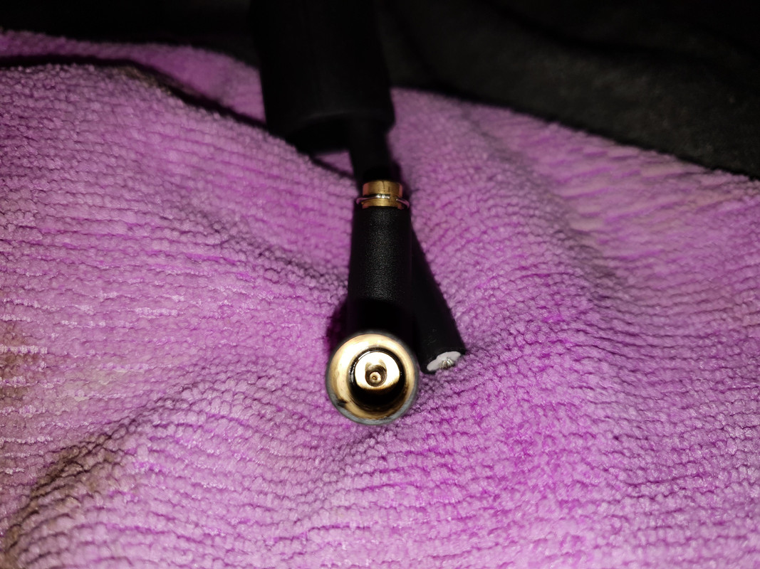
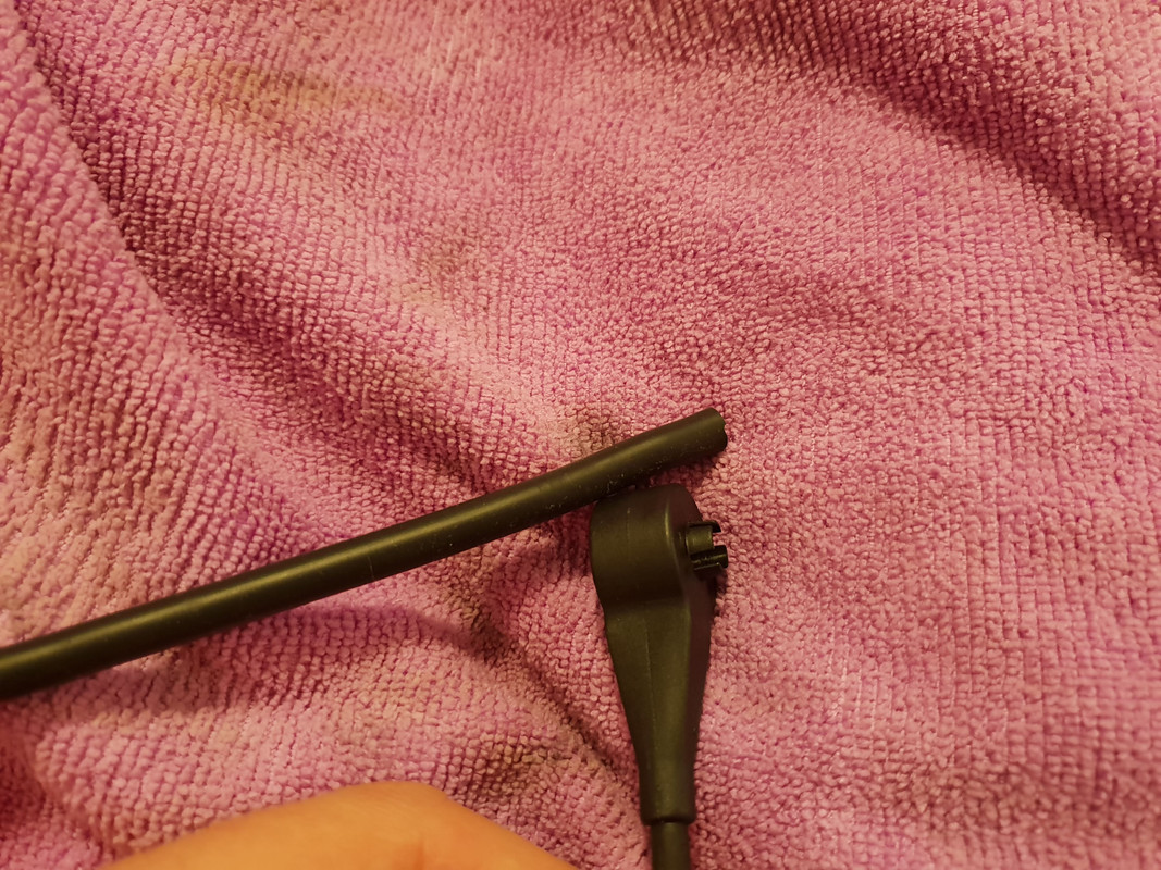
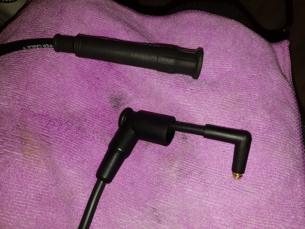
Here are the instructions about the correct position/direction of the donut on the ignition wire on cylinders 6 and 12, which someone sent me who is using aftermarket M70/M73 ignition wires I offer, where the plugs going to the distributors have a woodscrew type connection. The original Bosch or Bremi connections are different. Here's a quick & simple write up with pictures for installing cylinder identification sensors aka donuts on wires #6 and #12. These wires are identified by comparing length with the rest of the wires, them being the longest ones obviously. On the distributor boot end of the wire, get a slim flat blade screwdriver and slide it between the rubber boot and the wire. Use a lubricant of your preference, in my case WD-40, and spray it liberally. Follow up with more lubricant into the boot opening.
Work it in + you should be able to simply slide over the rubber boot towards the inner part of the wire like this. Hold the wire + push on the boot, don't pull on the cable. Use more lubricant if necessary as you don't want to pull on the wire + stretch it.
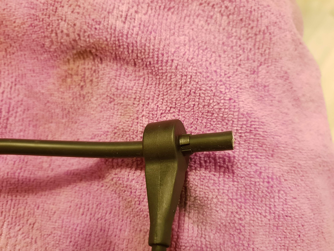
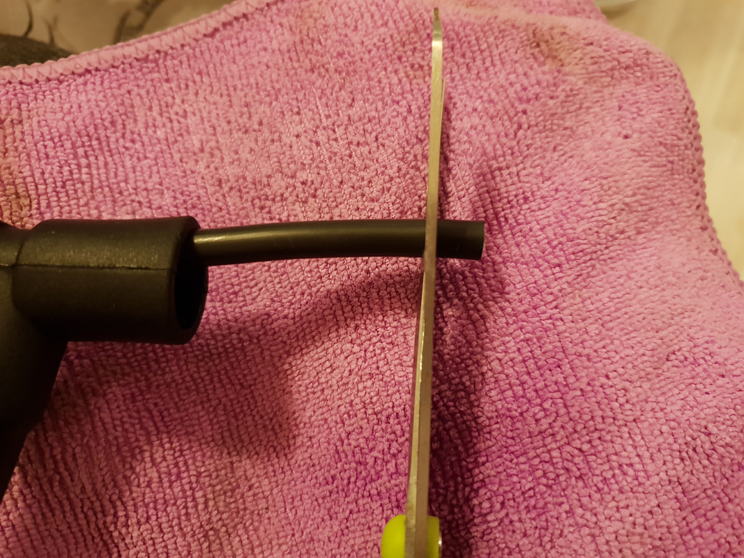
Grab and hold the wire with a microfiber cloth (for better grip) and start unscrewing the plug in anti-clockwise direction. It takes a decent amount of force to unscrew the plug so don't be afraid to use it as you can't really do any damage here.
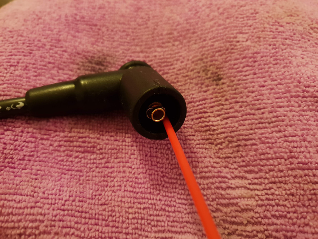
The plug simply unscrews and the woodscrew inside looks like this.
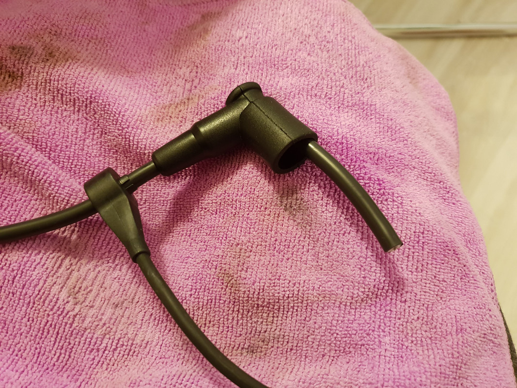
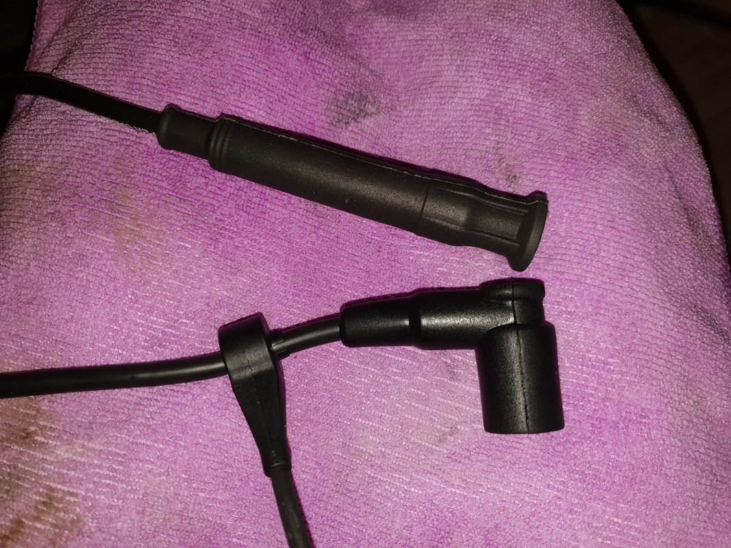
Remove the rubber boot from the wire and it's time to install the cylinder identification sensor. The direction in which the sensor is installed matters. If you are reusing your old sensors, simply install them using your old wires as a reference.
If you are installing new sensors, as I did, the 4 tips/prongs should be pointed in the distributor cap direction like this.
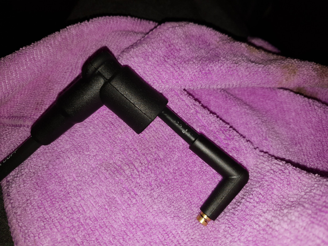
Lubricate the rubber boot and slide it back onto the wire.
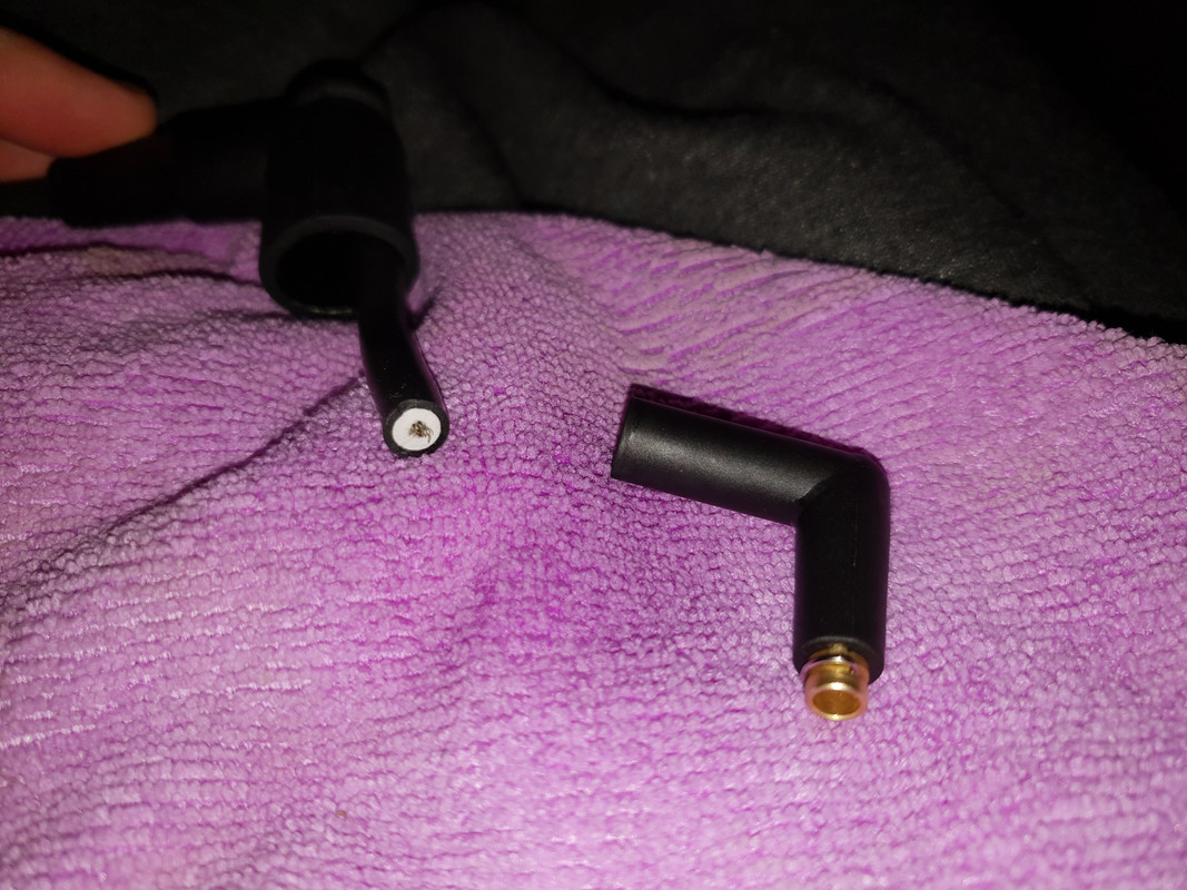
Grab a pair of sharp scissors and cut off 3 mm of the end of the wire thus getting a fresh bit of the wire where the woodscrew will go in.
Apply WD-40 on the end of the wire and reinstall the plug by screwing it back into place in the clockwise direction. Slide the rubber boot over the plug, if needed use more WD-40 to help boot slide easier without putting stress on the wire.
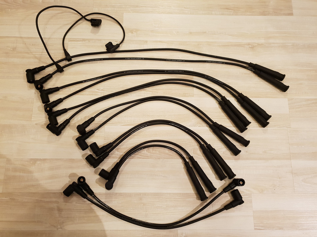
Now we want to verify that we have a proper connection and installation was successful. Break out your multimeter and set it to measure resistance (Ω). Stick a test lead at each end of the wire and you should be getting a readout of around 6 kOhm. This goes for all 12 wires, spark plug boot is 5 kOhm and distributor cap boot is 1 kOhm. The wire for ignition coil to the distributor cap is 2kOhm.
Additionally, you can wiggle and bend the wires slightly to make sure the connection is constant and doesn't drop.
Job well done.
Shogun tricks and tips for the E32 series are HERE!
shade tree mechanic
Moderator
changing the original spark plug boot from a German forum regarding M70/S70 ignition wires, seems in most cases the long boot going to the spark plug is the problem, the resistor inside the long boot get’s bad over the years, German text
Beim M70 werden Zuendkerzenhersteller 5000-OHM 12121710707 benoetigt. Ich mochte beim S70 Motor die Zundkerzenstecker wechseln. Ist es wirklich so aufwendig, wie es in der Original BMW Reparaturanleitung steht ? Laut dieser braucht man hierzu mehrere Spezialwerkzeuge....Lt. dem aktuellen BMW Ersatzteilkatalog finde ich folgende Teile, kann mir jemand sagen,ob das so vollstaendig ist + warum 3 Teile ausgewiesen sind:
Kerzenstecker. 12121710707 , Isolierhulse 12121736142 , Rundstecker 12121705656
--------------
Zuendkerzenstecker Bosch / Bremi mit 5KOhm Innenwiderstand. Im Laufe der Zeit zersetzt (oxidiert) der im Kerzenstecker enthaltene Metallfilmwiderstand sich und der Zuendstrom wird zu schwach. Das Wechseln der Kerzenstecker ist denkbar einfach, solange die Kupplungshuelse noch fest mit dem Kabel verbunden ist. du schneidest das Gummi des Kerzensteckers am oberen Ende vorsichtig auf, damit die Keramik freiliegt. mit einem kleinen Hammer nun den oberen Teil der Keramik zerschlagen, bis die silberne Kupplungshuelse freiliegt. Die Kupplungshuelse kann nun mit einem Dorn entriegelt und abgezogen werden. Der Neue z.B. Bremi / Bosch Kerzenstecker wird nun am Kabeleinlass mit etwas Fett oder Vaseline geschmeidig gemacht. Nun einen kleinen Schraubendreher am Kabel entlang in die Huelse einstecken und durch das Kabelloch des Kerzensteckers fuehren bis er hoerbar einrastet. Hierzu gibt es ein Spezialwerkzeug, eine Ahle welches das Zuendkabel umschliest und auf der Kupplungshuelse aufsetzt.
TRANSLATION: The M70 requires spark plug boot 5000-OHM is p/n 12121710707. I would like to change the spark plug boot on the S70 engine. Is it really as difficult as it is described in the original BMW repair manual? According to this one needs several special tools ....
Accdg to the current BMW spare parts catalog, I find the following parts, can someone tell me, if this is so complete + why 3 parts are shown: spark plug boot 12121710707, Insulating sleeve 12121736142, Round connector 12121705656
--------------
Reply: You will need spark plug boots Bosch / Bremi with 5KOhm with internal resistance. Over time, the metal film resistor contained in the plug connector decomposes (oxidizes) and the ignition current becomes too weak.
Changing the plug connector is very easy, as long as the coupling sleeve is still firmly connected to the cable. Carefully cut the rubber of the plug boot at the top so that the ceramic is exposed. Smash the upper part of the ceramic with a small hammer until the silver coupling sleeve is exposed. The coupling sleeve can now be unlocked and removed with a mandrel. The new e.g. The Bremi / Bosch spark plug connector is now made flexible at the cable inlet with a little grease or Vaseline. Now insert a small screwdriver along the cable into the socket and guide it through the cable hole of the plug boot until it clicks into place.There is also a special tool for this purpose, which wraps around the ignition cable and attaches it to the coupling sleeve.
-----------------
The defective spark plug boot is now replaced. I bought the BERU tool EFS7 (introductory probe), so that you get the cable including the detent sleeve quite well into the boot. The engine is now running well again even at low speeds, unbelievable what effects a defective spark plug connector can have ... I have modified the tool handle by grinding a hollow line, so that the cable can run through better ....
picture below of the spark plug side and the distributor side, I cut an original Bremi open. The genuine spark plug boot/socket is quite expensive, for example BREMI 13226/5 = 12121710707 regular price about $35.00/piece.
Alternatively one can have from me the aftermarket ignition wires for M70/M73
Last edited by shogun; 04-04-2020 at 07:04 AM.
Shogun tricks and tips for the E32 series are HERE!
 Posting Permissions


 Reply With Quote
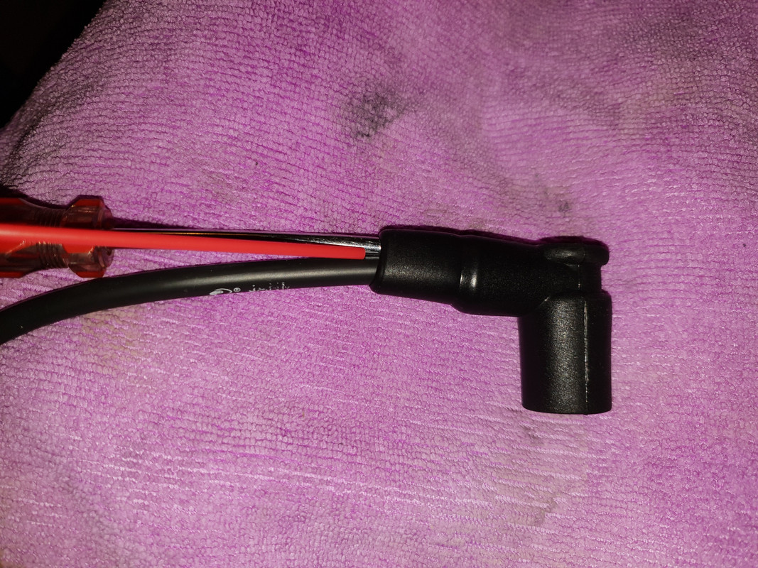

Bookmarks