
 Member
Fits perfectly with the HF motto "Use it once and throw it away"?Originally Posted by TipsyMcStagger

Member
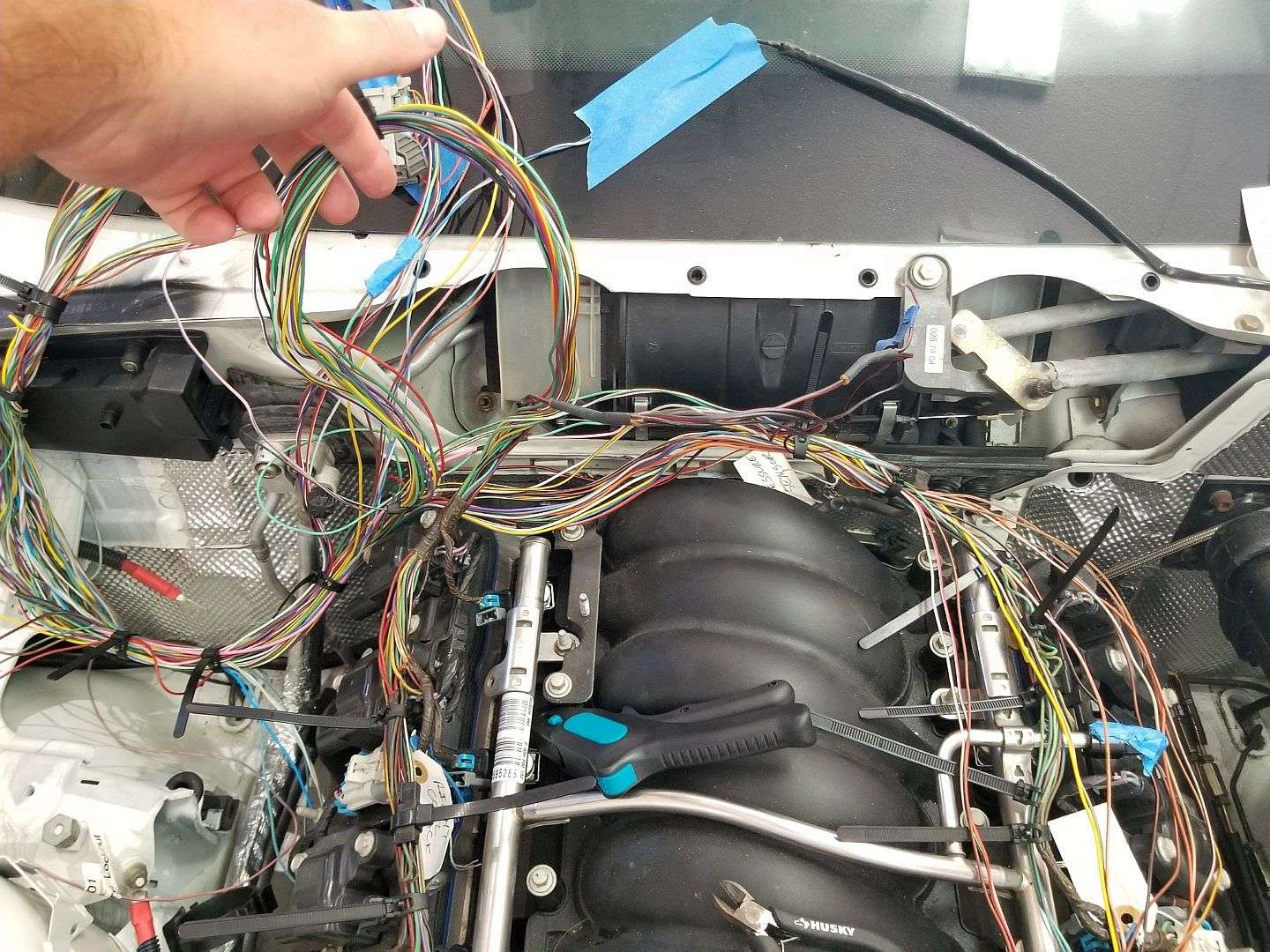
I hadn't touched the car pretty much since my last post. I'm feeling pretty shitty that I've let this languish, so I got back in the garage these past coupe of days to start the engine wiring. This was both a good thing and a bad thing. Good in that any progress is progress but bad in that I realized this is not going to move as quickly as I'd hoped.
Even though I've clearly set the record for longest E36/LSx swap ever, the time has worked against me. I have data-dumped so much of what I once knew. I have notes, but what I'm realizing is that although I'm not the first to use an E40 PCM in an OBD2 E36, much of the info that I have in my notes and/or bookmarked doesn't address A/C or DBW cruise control, or the info is mostly 411 PCM or pre-OBD2, etc. etc. So, I'm back spending more time in front of the keyboard rather than in the engine bay.
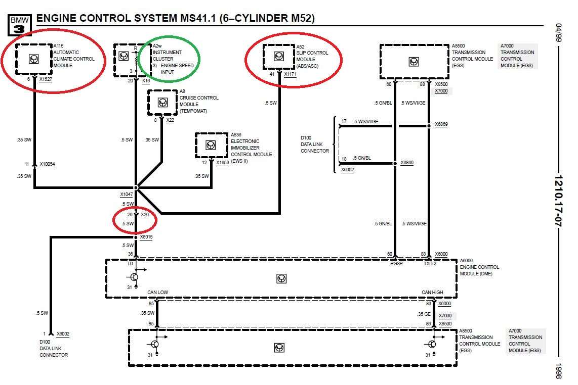
I also realized my little brain-fart last January, when I put power to the wrong X20 pin while trying to energize the fuel pump might not have been as innocuous as I'd hoped. I was lucky that the instrument panel was not installed at the time, but in combing through the ETK, it looks like X20-20 (the pin I accidentally energized with 12V) branches to the Automatic Climate Control Module. It remains to be seen whether or not it was affected. Hell, on second glance, it looks like it goes to the ABS module too. Good grief.
I'd previously unsheathed the GTO harness and removed all of the pins I won't be using. I guess the stock GTO PCM location is just behind the headlight on the drivers side, so moving it to the E36 DME location leaves a lot of extra length leading to the right injector/coil bank. That will need to be addressed.
Starting on the engine wiring.
Extra harness length.
This shows where X20-20 branches to. The green circle is the instrument cluster for the tach. The red circle is the climate control module.
Last edited by TipsyMcStagger; 05-20-2019 at 10:01 AM.
БМВ Фанат!
I would suggest to first get the car running and working correctly before modifying/shrtening the wires. If something does not work you will have hell of a time figuring out if it was your wiring, shortening or general problem.
- 96 328is 6.0L. (LS1 to LS2 build thread: http://forums.bimmerforums.com/forum...ad.php?2098938)
- 96 328is 5.7L. (LS1 build thread: http://forums.bimmerforums.com/forum....php?t=1289987)
- 95 ///M3 6.0L. (LS2 build thread: http://forums.bimmerforums.com/forum....php?t=1619249)
- 97 ///M3. (e46 Fender Flares/track car build thread: http://forums.bimmerforums.com/forum....php?t=1727098)
- 96 328is (Dual Fuel Pump to Surge Tank thread: http://www.bimmerforums.com/forum/sh...ad.php?1964025)
Member
I agree with Bimerok! Get it running first...if for no other reason than to rekindle the fire!
Member
Thanks for the feedback, guys. I know I don't have to run it very long to verify that it runs, but I'm just concerned about burning the harness if I fire it up with the harness all willy-nilly.
I've been using non-insulated butt splices crimped with a pair of West Mountain Radio ratcheting crimpers (with the proper die-set), sealed in 3:1 adhesive shrink for all of my splices for quite some time now (including the redo of the ABS harness). This has pretty much resulted in me retiring my soldering iron.
You can hang lead from a properly crimped splice and the wire will break before the crimp will fail. And the 3:1 adhesive heat shrink is completely waterproof. I live on a salt water canal and made some underwater LED lights that I wired in this manner. I had them submerged in saltwater for several years and never had any problems.
All that being said, I know where you're both coming from and your advice is noted and appreciated.
NONINSULBUTTCONN.jpg
Member
I am working through the same process getting restarted with my project after almost a year long break. I ended up cheating and going with a standalone harness from https://www.bp-automotive.com/. With the essential engine wiring out of the way I can focus on the other bits like extending the ABS pump wiring.
Member
Yeah, I know using a ready made harness eliminates a bunch of work, but I'm pretty intent on doing the electrical myself.
I know you guys are going to think I'm nuts but given the number of wires that need to be shortened between the PCM and the right side injector/coil bank, there's not a lot of length remaining along the run to stagger the splices. Even though the crimp splices I detailed above are pretty low profile, the heat shrink adds some girth. Placing a dozen or more splices next to one another creates a bulge in the harness that is unsightly and hard to manage.
So, I spent a bunch of time today considering alternatives. The super slick and neat way to shorten the harness would be to depin the connectors at the PCM, shorten the wires and crimp-on new terminals (pins). The result is effectively a "factory" shortened harness with no splices. I think the LS1 411 ECM connectors are a little easier to deal with than the E40 Delphi (now Aptiv) Micro 64 connectors.
I grabbed my J1 connector to experiment and retaught myself how to remove the terminals. I had some of the correct Delphi Micro 64 terminals that I'd bought quite a while ago. I experimented with a few crimps.
Using a crimp tool identical to this one I am able to make solid, neat crimp on the bare wire. The problem I'm having is making a tidy crimp on the insulation/strain relief. This crimper is too large for the insulation crimp and another pair of crimpers I have are too small. It's critical that the insulation crimp be compact and not cause the terminal to bend. Otherwise, it becomes problematic inserting the pin back into the connector.
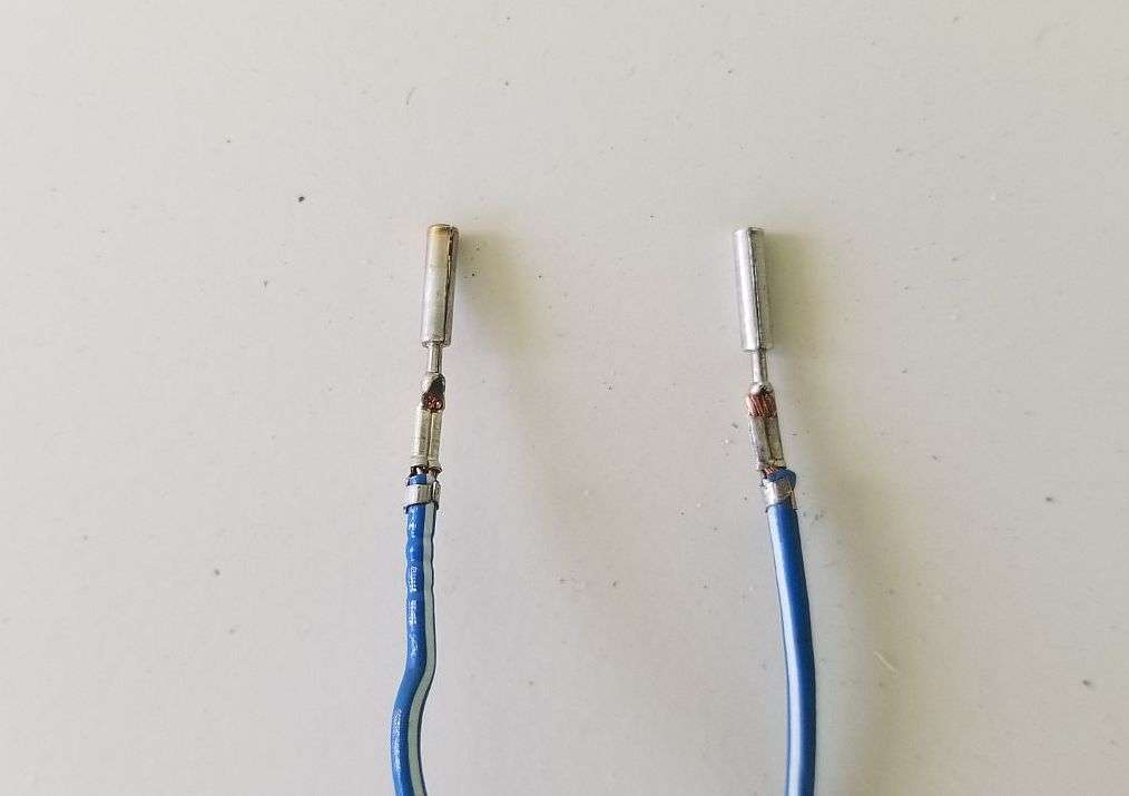
In second picture below, the left crimp is a factory crimp I removed from the blue C1 Micro 64 connector. The crimp on the right is mine.
If I can figure out how to get a consistent, tidy, compact crimp on the insulation, I'd like to proceed with this process to shorten the harness.
C1 Connector.
Factory Crimp on Left. My crimp on Right.
Member
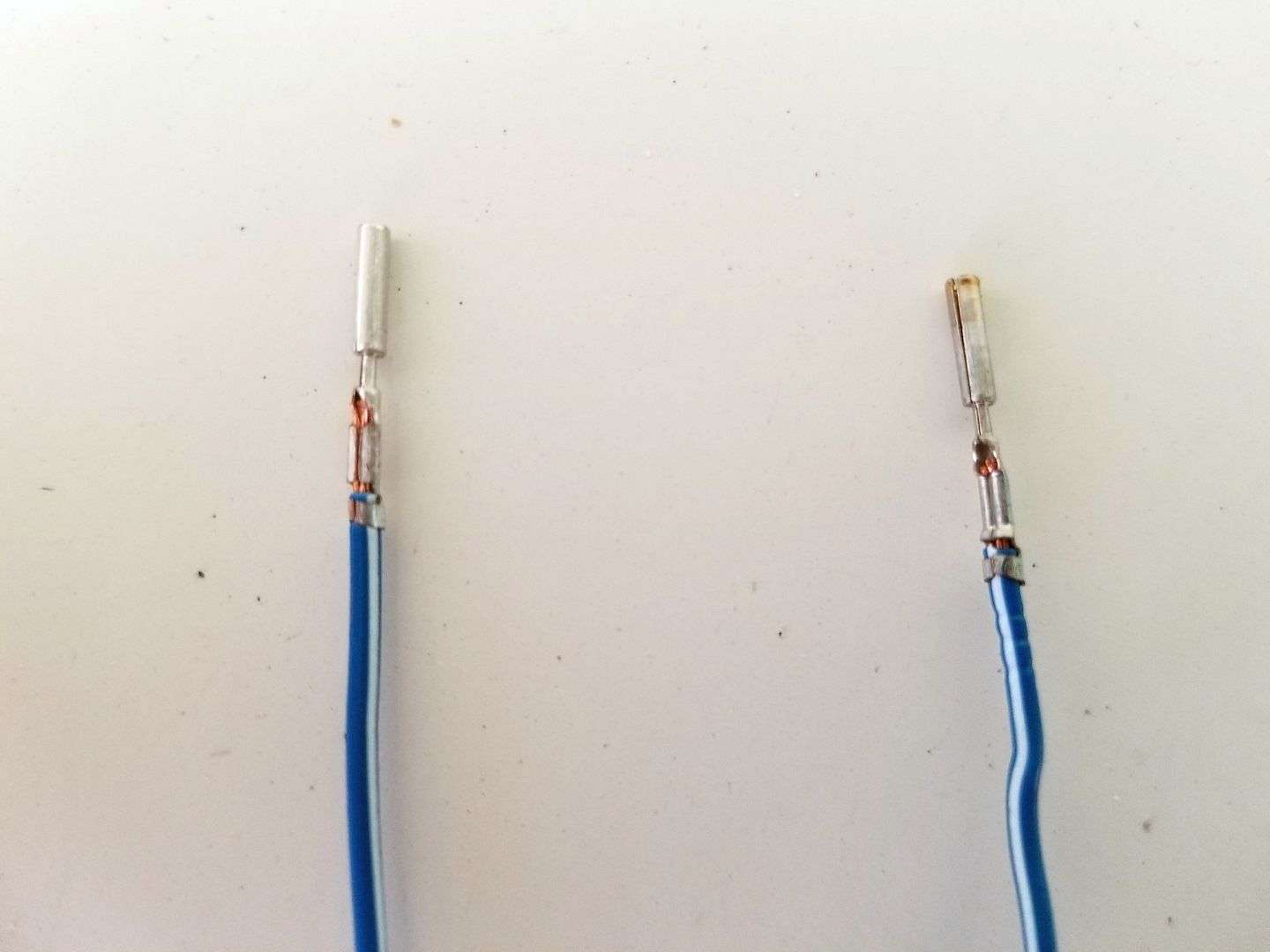
I experimented some more and I think I've got it figured out! It's a three step process using two different tools, but I was able to achieve a very neat and compact crimp without deforming the terminal. It easily slides back into the connector body.
I know in the picture you can see a little copper between the "folds" of the main crimp, but it's a solid crimp. The close-up picture makes it look like it's not tight but it's very tight. Kind of an optical illusion.
My Crimp on Left. Factory Crimp on Right.
Last edited by TipsyMcStagger; 05-21-2019 at 06:49 PM.
Member
I've shortened no fewer than 30 wires at the C2 connector by removing each wire, cutting and crimping-on a new terminal. This is every wire that leads to both the left & right coil and injector banks, plus a few others.
I hope I'm not jinxing myself but this is where I'll tell Leo and Tim that they can have their fill of I-told-you-so's IF there comes a day where I've checked, double-checked and triple-checked everything and cannot get the car to start or run properly. I know it's not the smartest approach but dealing with all of the extra wire length was maddening.
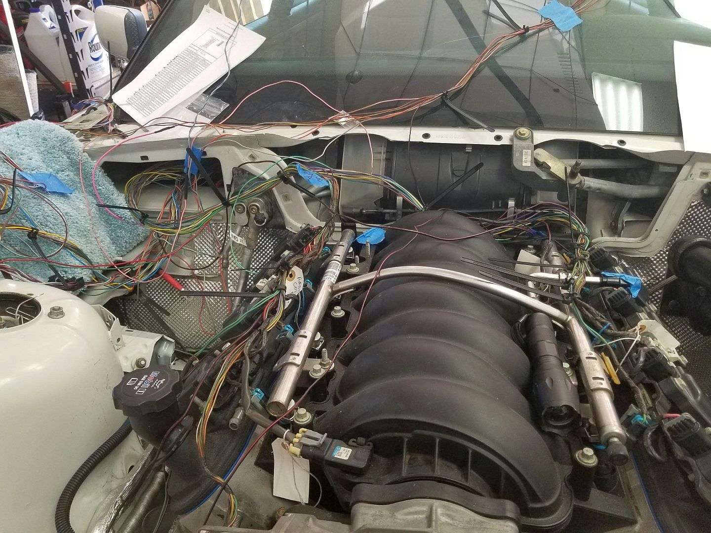
With the E40 PCM, C2 is pretty much the bulk of the main engine harness. C3 is down to just a few wires, after removing the emissions and other unnecessary stuff. And C1 will be the connector that mainly ties the PCM into the chassis harness.
I know if doesn't look like much but C2 is resting in the DME cubby in this pic. It's probably still 6" longer than need be but it's hard to know exactly how everything will be routed and dressed. I'd rather it be a little long than a little short.
Member
I can't offer any help but happily following along, this wiring work and progress is cool to see lol
Member
I routed everything and loomed it all up with the wires full length. Once I was satisfied with my layout, I cut the excess out and spliced the wires back together.
Member
That's probably the smartest approach. But that ship has sailed
Member
I'm knee deep into wiring and I'm bouncing back and forth between feeling like I'm headed in the right direction and feeling completely lost and overwhelmed.
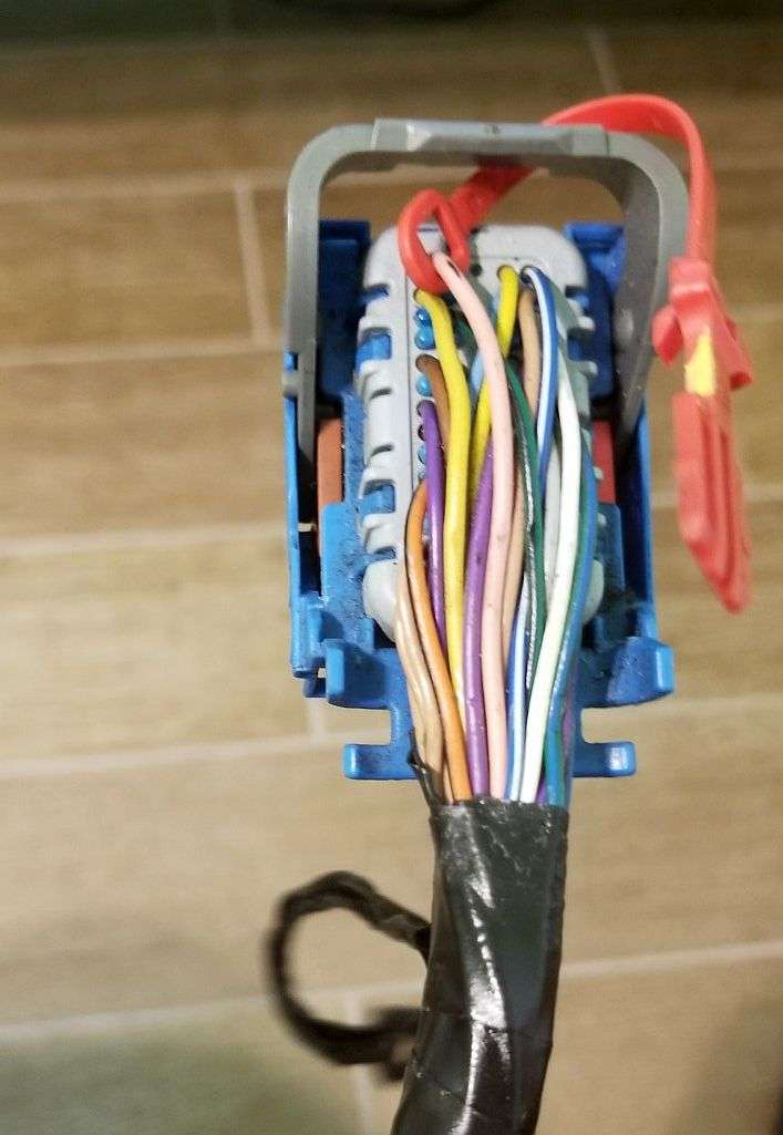
My intent is to reuse the three relays that were originally attached to the fuse box. In 1998 these were designated (front to back) as ECM, Fuel Pump and Secondary Air Pump.
I've identified and labeled the wires in all three relay sockets and now I'm trying to make sense of how these would get wired into the swap.
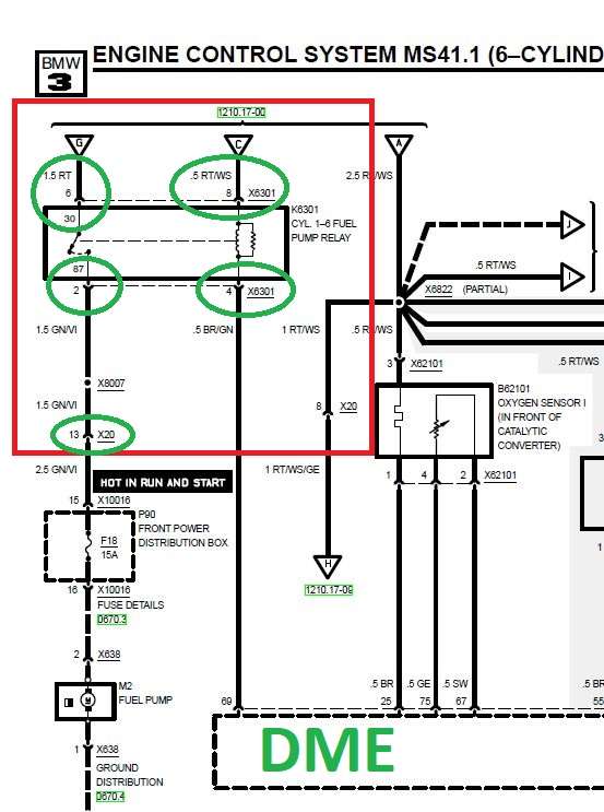
Focusing on the Fuel Pump Relay diagrammed below, I've got a handle on three of the four wires.
Pin 6 will bring high amperage 12V into the relay (relay contact 30). Pin 2 will carry that high amperage 12V out of the relay (relay contact 87) and connect to X20-13, which will power the fuel pump.
Pin 4 will be the switching signal from C1-45 of the E40 PCM (formerly from the BMW DME). This is what controls whether the relay is "on" or "off."
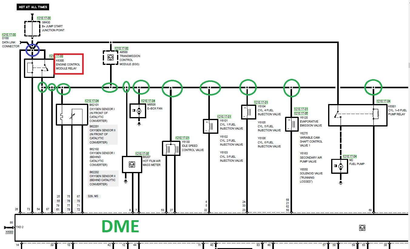
What I'm confused about is Pin 8 (RT/WS). If I'm interpreting the triangle with a "C" in it correctly, that is showing current coming into the relay. There is seemingly no ground wire in a four pin relay (two of the three relays are four pin. The Secondary Air Pump relay is five pin).
So please help me understand Pin 8. If I'm correctly interpreting the second diagram below, it appears that 12V hot (blue circle) feeds the ECM relay, which when energized then becomes the power source for all of the green circles (in the second diagram), including Pin 8 of the Fuel Pump Relay?
In other words, the Fuel Pump Relay cannot receive switching power (Pin 8) until the ECM relay is activated? The Fuel Pump Relay receives the switching signal from the PCM but receives switching power from the ECM relay?
Is this correct?
Last edited by TipsyMcStagger; 05-26-2019 at 02:38 PM.
Member
Okay guys...I think it's starting to make sense. Firstly, I think everything I wrote in the previous post is correct, right? But that was the way BMW did things.
In reading though my notes and digging through old bookmarks, etc. it seems we don't need to switch the GM PCM through a relay, correct? And if the PCM is not relay controlled, then there's really no need to have the fuel pump relay powered by another relay, correct?
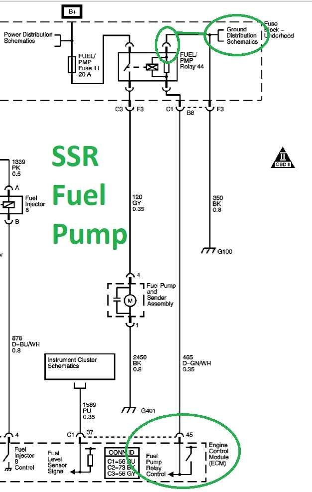
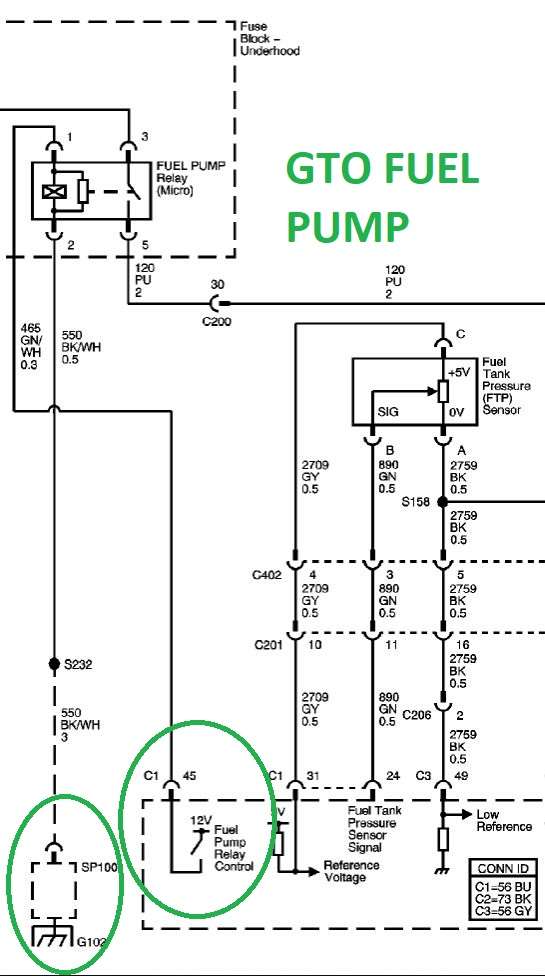
I looked at both the GTO and SSR fuel pump schematics (I have an SSR OS on my GTO PCM). Both appear to show the PCM controlling the Fuel Pump Relay (C1-45) with +12V and the opposite side of the relay control coil (Pin 8 above) simply going to ground.
So I simply wire Pin 8 (RT/WS) to ground and the other three pins as previously described and I should be good to go?
GTO Fuel Pump Relay
SSR Fuel Pump Relay
Member
C'mon guys...I know I posted over the holiday weekend but I need some positive reinforcement
БМВ Фанат!
Hey Brad, Sorry I can't dive deep into the wiring at the moment, got other stuff going on that I keeps my head elsewhere
But to answer some of your questions - you don't need a relay for the PCM and you don't want to set up your relays so one triggers another, etc... For PCM all you need is constant power and switch power. I think BMW did it that way as part of their theft prevention system, but not 100%.
In any case, I'm sure you know how the regular relay works so which pin gets hot/ground/trigger/output can be figured out or looked up. Keep in mind that not all BMW relays are the same. Some of them have completely different pinouts for different purposes and might not work as a normal relay.
What I did in my swap is tied first relay to supply voltage for Coils and Fuel Injectors. The middle relay supplies voltage for MAF, Reverse Lockout, and O2 sensors. Finally the third relay supplies voltage for Fuel Pump. All relays get triggered by the PCM.
Hope that helps a little. If you have more specific questions, post them up and I'll try to see what I can answer when I get a bit of time.
Glad to see you working the wiring!!! So close!
Last edited by bimerok; 05-28-2019 at 07:27 PM.
- 96 328is 6.0L. (LS1 to LS2 build thread: http://forums.bimmerforums.com/forum...ad.php?2098938)
- 96 328is 5.7L. (LS1 build thread: http://forums.bimmerforums.com/forum....php?t=1289987)
- 95 ///M3 6.0L. (LS2 build thread: http://forums.bimmerforums.com/forum....php?t=1619249)
- 97 ///M3. (e46 Fender Flares/track car build thread: http://forums.bimmerforums.com/forum....php?t=1727098)
- 96 328is (Dual Fuel Pump to Surge Tank thread: http://www.bimmerforums.com/forum/sh...ad.php?1964025)
Member
Thanks Leo. I was really trying to make it so I could "repurpose" the fuses in the BMW box for everything you enumerated above. But after a lot of reading/researching, the only one that seems like a no-brainer is the fuel pump. The output of the relay gets connected to X20-13, which is protected by F18.
The Left and Right coil/injector banks are separated each on 15A fused circuits in the GTO, so I tend to want to keep it that way. As you did, I will use one of the three BMW relays to feed these circuits but I don't see any option here for reallocating a BMW fuse. Unless I'm missing something obvious, I'm going to have to add two 15A fuses "external" of the BMW fuse box.
And the last BMW relay, as you mentioned, will be MAF, Reverse Lockout, and O2 sensors. I don't know if you have it in your notes but did you run these through X20, so they are protected by a fuse in the BMW box? I haven't been able to figure that out and think I might have to fuse that "externally" as well.
Thanks again, Leo. It's sad how much I've forgotten but I'm feeling motivated, despite the record heat we've been having this week.
БМВ Фанат!
On the fuel pump, you are correct, the output of the relay gets connected to x20-13, which I think like you said is going through a fuse.
For the Coils/Injectors, I went with BMW approach and did not add any fuses to it. I just connected both banks to the relay output and left it that way. I did the same thing for the MAF, Reverse Lockout and O2. If you want to keep it GM style with fuses, you can easily add external fuses on the outputs from the relays or try to figure out which one of BMW's you can repurpose or find if there are spare locations and wire them in.
All relays except for Fuel Pump are triggered by Ignition Switched Voltage from X20-21. The fuel pump is triggered by my PCM Fuel Pump wire, which is in my case (PCM) C1-45.
- 96 328is 6.0L. (LS1 to LS2 build thread: http://forums.bimmerforums.com/forum...ad.php?2098938)
- 96 328is 5.7L. (LS1 build thread: http://forums.bimmerforums.com/forum....php?t=1289987)
- 95 ///M3 6.0L. (LS2 build thread: http://forums.bimmerforums.com/forum....php?t=1619249)
- 97 ///M3. (e46 Fender Flares/track car build thread: http://forums.bimmerforums.com/forum....php?t=1727098)
- 96 328is (Dual Fuel Pump to Surge Tank thread: http://www.bimmerforums.com/forum/sh...ad.php?1964025)
Member
Thanks Leo. That's pretty much what I thought. I'd really like to keep the coil/injector banks fused the way GM had it, as well as the MAF/Reverse Lockout/O2's, so I guess I'll just have to add "external" fuses.
Like I said, sometimes I feel like the "light bulb" has come on and the dots start to get connected. Other times, like this morning, I spend hours pouring through the ETK trying to figure something out.
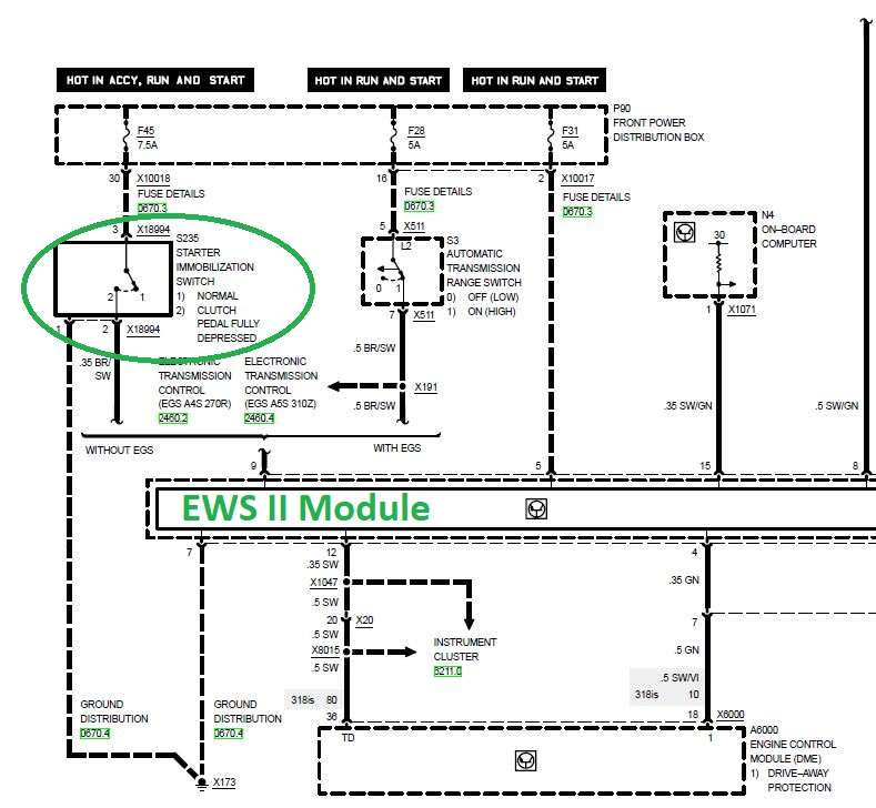
Right now, I'm trying to figure out how to wire the clutch-safety switch to prevent the starter engagement without the clutch being depressed. Since the starter engagement signal comes from X20-18, I'm not sure if I need to somehow tap into the clutch safety switch, or it the stock wiring does this for me already. The clutch safety switch is wired through the EWS system, so this is what's confusing me. I'm not sure if that's still a player or if I need to somehow rewire this.
Head spinning.
БМВ Фанат!
I don’t believe that on my 96 I had a clutch safety. From what I can remember I could start it without depressing the clutch.
You can wire it up as it is and then if your clutch safety doesn’t work, you can add that “feature” later. By the way, are you sure you had clutch safety?
- 96 328is 6.0L. (LS1 to LS2 build thread: http://forums.bimmerforums.com/forum...ad.php?2098938)
- 96 328is 5.7L. (LS1 build thread: http://forums.bimmerforums.com/forum....php?t=1289987)
- 95 ///M3 6.0L. (LS2 build thread: http://forums.bimmerforums.com/forum....php?t=1619249)
- 97 ///M3. (e46 Fender Flares/track car build thread: http://forums.bimmerforums.com/forum....php?t=1727098)
- 96 328is (Dual Fuel Pump to Surge Tank thread: http://www.bimmerforums.com/forum/sh...ad.php?1964025)
Member
For what little it is worth, in GM Gen-III applications the clutch pedal position (CPP) was NOT used to prohibit starting. It was only used for cruise control and engine control during shifting. (All of this is according to Mike Noonan's "GM Gen III LS-Series Powertrain Control Systems.")
I personally would like to incorporate a safety lock-out, as I have gotten kinda used to it!
Last edited by motorV8ed; 05-29-2019 at 12:17 PM.
Diving in at the shallow end!
Member
I think the clutch safety switch, or as BMW calls it, the "Starter Immobilization Switch" is a post 1996 thing. It's in several schematics in the 1998 ETK. At any rate, I think that's what I'll do (skip it for now), unless someone chimes in who knows how to address this. It's wired through the EWS module and I'm not sure if the starter cutout would still be functional as-is or if the pedal switch would need to be somehow wired directly into the X20-18 circuit (bypassing the EWS module)?
MotorV8ed, the '98 actually has two switches on the pedals. One is the "Starter Immobilization Switch" and the other is for cruise-control interrupt. I'll be attempting to make the cruise-control functional with the E40 DBW, so I'll need to integrate that switch.
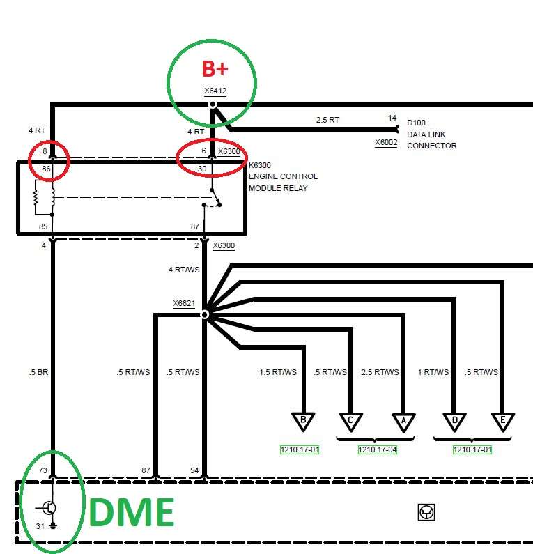
To Bimerok's earlier point about different BMW relays being wired in different ways; I was just laying out how I'll repurpose the the BMW Engine Control Module Relay for the GM Injector and Coil banks. There are two common (combined) red B+ leads in this relay on post #'s 30 & 86. If I'm reading the schematic correctly, this relay was activated by the BMW DME providing a ground on Relay Post 85 through DME Pin 73.
It also appears, in looking at the GTO schematics, that the Injector/Coil banks were directly fused (not run through a relay).
So what I'm thinking is that if I wire this so that X20-21 provides switched 12V to activate the relay, I would need to separate the hot leads that are currently combined on the relay (post #'s 30 & 86) and instead make Post 86 a ground. EDIT: Or, since Post 85 is already wired Brown, I could make Post 85 Ground and Connect X20-21 to Post 86. It shouldn't matter which side of the coil is Switched vs Ground.
Is my line of thinking correct?
From the 1998 ETM, showing the clutch safety ("Starer Immobilization)" switch.
ETK Engine Control Module Relay Schematic. Two Combined B+ Hots on Relay Post #'s 30 & 86 with the relay triggered by Ground through the DME. This would need to be changed for X20-21 to trigger the Relay with 12V and Relay Post 8 would need to be Ground (and obviously separated from Post 30)?
EDIT: Or, since Post 85 is already wired Brown, I could make Post 85 Ground and Connect X20-21 to Post 86. It shouldn't matter which side of the coil is Switched vs Ground.
Last edited by TipsyMcStagger; 05-29-2019 at 01:54 PM.
Member
Every single manual BMW has a clutch safety switch. It is not a thing starting in 1996.
Member
Unless there is a suppressor (or "freewheel" or "flyback") diode to dissipate the EMF generated by interrupting the coil. The schematic shows a resistor (which would be fine), but I would check to see if that matches reality or not!
(Side note: May I ask where you are getting those schematics from?)
Diving in at the shallow end!
Member
Suppressor, "freewheel" and "flyback" is definitely getting above my limited electrical vocabulary. I was under the impression that simple automotive relays are not polarity sensitive?
All of the schematics are straight from the 1998 BMW ETK.
 Posting Permissions


 Reply With Quote
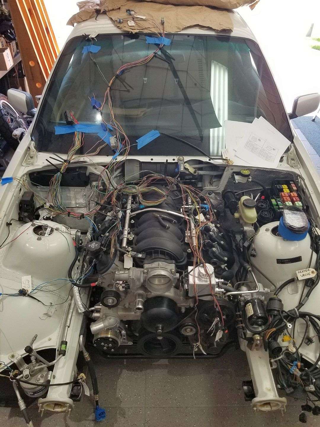
Bookmarks