
 Member
Here we remove the steering box from a 1997 bmw 840ci and replace about two dozen seals.
Earlier boxes and 850 procs with differ slightly.
The motivation was to confirm a failure diagnosis document in another thread.
This small task was made into a big challenge simply by the refusal by original manufacturer (ZF) to supply rebuild kits directly to end users.
The seals used herein are now precisely documented and in theory could be sourced independent of the oem.
The procedure shown below is not a complete rebuild because...
- My seal kit and documents did not cover the servotronic control.
- My tools, skill and kit did not cover the removal of roller bearings on the shafts.
- My documents did not reveal how to service the torsion control valve section of the input shaft.
**** Removal/Install ****
Time: about 30 minutes each way for the pro w/tools on game day. About 2-3 hrs each way for beginners.
Disconnect the battery and leave the steering wheel unlocked.
Jack the car, remove wheels and prop up the engine, independent of the subframe.
Position a lift under the subframe.
Disconnect hydraulic lines to the steering box, thus releasing fluid.
- Hi-side at regulator. 17mm.
- Lo-side at steering box. 22mm + 12inch extension.
- It's also a quick task to drain the reservoir (5mm hex) but I can't say whether that's absolutely essential.
Unbolt the subframe.
Per side...
- 2 Engine mount nuts (17 & 13mm)
- 3 forward (17mm)
- 1 Control arm anchor (22mm)
- 2 rear (15mm)
- 1 heat shield (10mm)
Disconnect/unbolt...
- Servotronic harness
- Steering column U-joint.
Lower subframe.
!!! Tilt front of subframe down so that the steering box clears the V8 engine mount.
Only then will the box input separate from the steering column.
Disconnect the pitman arm from the steering box. 15mm + 6in extension
Unbolt and remove the steering box. 17mm & 17deep, 19mm & 19deep.
**** Disassembly ****
Time: 10min for the pro. 1hr for beginners.
Vocabulary
Remove perimeter bolts on output shaft cover. Manage/track the washers buried by paint.
Remove locknut (17mm w/o paint) from lash adjuster on top of the cover.
Break paint seal (say with box cutter blades) and turn the lash adjuster (5mm hex) to pull the cover away from the housing.
Inside you will find...
- approx 1-1/2 cup (350ml) hydraulic fluid.
- the output shaft
- the rack
Remove the orientation cap on the input shaft.
Here opposing chisels unstick the cap from hardened gunk.
Unbolt the input shaft housing.
Break paint seal at either the input housing and the intermediate housing.
Remove the input shaft and rack.
The control section of the shaft contains about 1/2 cup (100ml) of hydraulic fluid.
Separate the rack off the input shaft by rotating the input shaft (left-handed action, CW to remove).
Listen as the 23 balls fall and collect at the bottom of the rack.
**** Seal replacement ****
Time: 20 min for pro with organized inventory. 2hrs for the confused beginner.
A seal kit was obtained, definitely without any thanks to the oem.
The part numbers shown in pics below were assigned arbitrarily as I inventoried the kit and wrote out a spreadsheet.
The output cover, using magic tweezers.
- Oval seal, inside #7
- O-ring, outside #11
The roller bearing on the cover prevented replacement (by me) of...
- Yellow seal, #6
Housing seals at outshaft lower end.
- Oval seal, inside, #7.
The roller bearing on the housing prevent replacement (by me) of...
- yellow seal, #6
- blue seal, #22
Input shaft.
- Bands, #3
- O-rings, #9
- Band, #4
Original bands, layered over o-rings.
Check valve cover
- O-ring, #15
Input housing.
This spring seal was not replaced due to tooling and priority.
- Spring seal, #23 (not 22 as per typo in manifest).
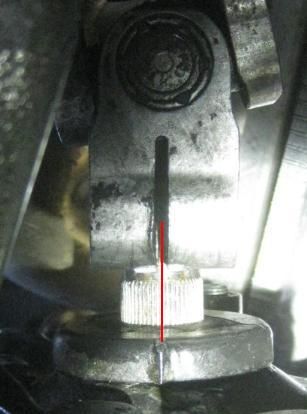
Input shaft cap, #24.
The pointer is an extension of the tick on the shaft, covered by the U-joint during install. Shown not seated yet.
Intermediate housing, control side
- Band, #2
- O-ring, #8
- O-ring, #10
- O-ring, #16
Intermediate housing, rack side
- O-ring, #10
- O-ring, #16
Rack
- Band, #1
- O-ring #8
Rack recirc cover
- Band, #5
**** Assembly notes *****
Position the input shaft in the rack with approximate 6cm separation.
Insert qty 16 balls into hole A and rotate the input shaft until they appear at hole B.
Be alert for jamming, else start over.
Fill the recirc pipe with the remaining 7 balls and insert from A to B.
Fyi: The top shell has been withheld just for this pic, but this sequencing actually won't work. The balls interfer with the insertion of the half-shell.
The successful technique is to assemble and load the the recirc pipe,
then keep the rack and pipe almost level so that no balls fall out on either side,
then bring the pipe and rack together.
The hi-side hydraulic line must be installed blind. There is no access after box installation.
It has been demonstated that coming staight out to the side provides the correct orientation to mate with the regulator.
Shopcraft while we are here: This note was written six weeks prior, telling myself about the state of the project.
**** Install notes ****
Both the pitman arm and steering column U-joint have an rotation alignment according to tick marks on the shaft ends.
The convenient proxy on the pitman arm is the flat on the shaft where the pinch bolt passes.
Then raise the subframe, trailing end first until the box clears the V8 mount.
The column U-joint aligns with the pointer on the input shaft cap.
 Posting Permissions


Bookmarks