
 Member
The H31 brake booster on a '97 840Ci is rebuilt using the kit supplied by BF member Max Lumen.
The 850 is quite similar but I titled this thread specific so that anyone can later post a HowTo with an 850 focus.
Two servo part numbers show up in the online EPC, grouped into early and later apps as follows: {credit: smc850ci}
* e32/750, 850/M70, CSi
* 850/M73, 840
As detailed below the two differ at least by the bolt count on the front MC mating flange.
However, online catalog pages tend to picture only the two-hole style used in the first group.
The rebuild kit covers both the earlier and later applications.
******
In the grand universe of wrenching this is a simple job. One warning though is that getting into the footwells is a significant hazard for the spine.
I'm still in good shape, early 50's, and survived the trauma.
This rebuild was motivated a rash speculation that the booster hydraulic path may be stuck open, leading to low system pressure, leading to loss of steering assist. The symptom list later grew to include brake pedal floor tap. The only doubt was whether the booster was stuck open because of internal issues or whether it was, say, due to the master cylinder failing to return. Fast forward: The booster was rebuilt and there was no change to the steering symptoms. However, after further swapping in a new MC and fluid and bleeding, it more apparent now that the pedal floor tap was rather a bottoming of the booster travel before getting into MC travel. Probable cause: low hydraulic pressure. Since both the steering and brakes are affected, probable source is the pump.
There are already booster rebuild writeups by others.
This writeup seeks to fill in some missing gaps, show cases the 840 specific parts, suggests some alternate wrenching techniques, and gives a headzup on which kit items go where.
And hopefully I'm concise.
References:
Brake Booster Rebuild Kit and Overhaul Info by Max Lumen.
Nice pics by mjrgroup.
The Brake Booster Job. A comprehensive view of the job featuring the 850, by Ahmed303.
H31 Brake Rebuild & Master Cylinder by George Fontes.
**************
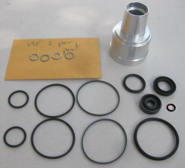
Here is the manifest of the all-inclusive version of the kit.
Inside the envelope are what I assume to be banjo washers, unused for this app. One thick medium size o-ring was also not required. I had to photoshop the smallest o-ring into the pic, as it was only later found hiding inside the spring retainer seal.
***** OK, get on with it already! *********
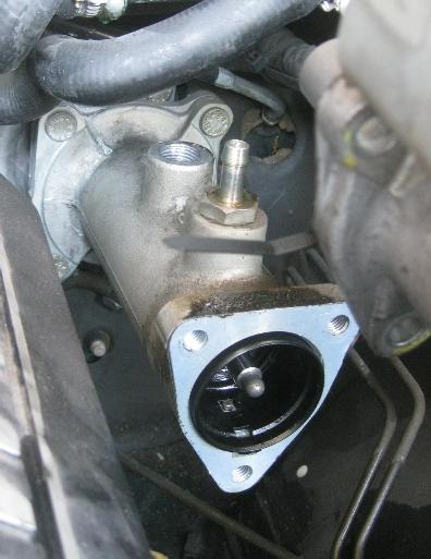
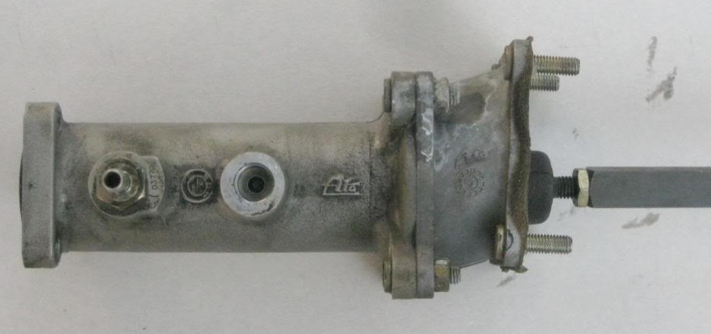
Compared to the H31 boosters shown in some other 750/850 writeups, this '97 840 booster has three (rather than two) holes in the master cylinder mating surface.
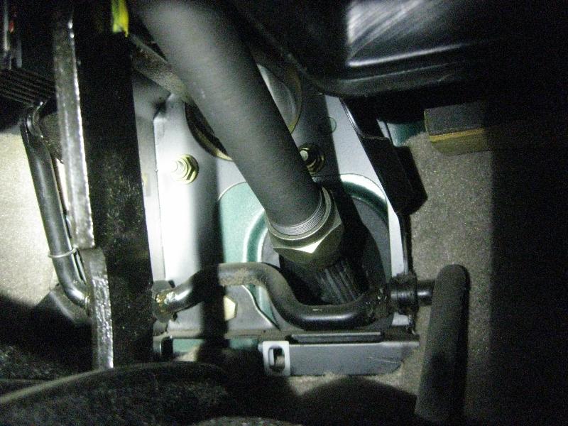
The hydraulic system was drained and the regulator removed and the reservoir pulled forward (with tie-wraps).
The MC was then unbolted and pulled up and away without opening the brake lines. No other disassembly or clearance was required in order to unbolt and remove the booster.
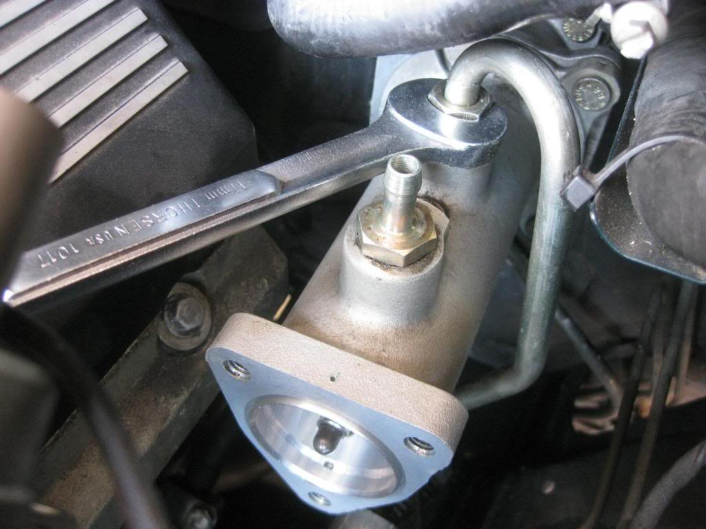
I found the rear port on the booster was accessible with a box wrench and coupling was not unusually tight. 850 owners have tended to come down from the top using a crowsfoot attachment and their connection is tight.
I found an articulated ratchet extension useful to access the MC mating bolts (allen head btw).
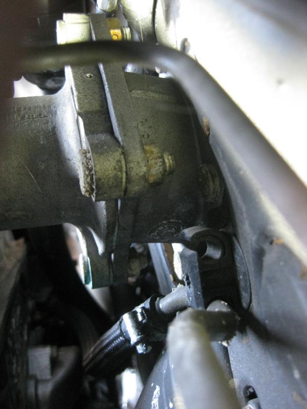
Another reminder that a 90-degree DOHC lurks under the 840 hood. Afaik, the 850 does not use the rear offset casting.
In either case, the rear-most bolts pass through the firewall and are accessed behind the pedals in the footwell.
On the offset casting for the 840, it would be nice if the forward bolts were pointing forward allowing the booster to be removed from the engine side. These forward bolts are also visible from a void in the fender wall. Getting back in there though would require app specific tools, like a long ratchet wrench with a short throw plus an angled box head. However the trouble involved would be greater than merely unbolting from the footwell, and you would still have to get into the footwell to release the actuation bar from the brake pedal.
The Ahmed303 writeup provides thorough guidance on footwell access.
Within the footwell, the actuator arm is fastened to the brake pedal arm by a yoke and pin. The brake switch provides intentional interference with the pin removal and therefore should be removed (and then replaced at the end of the project).
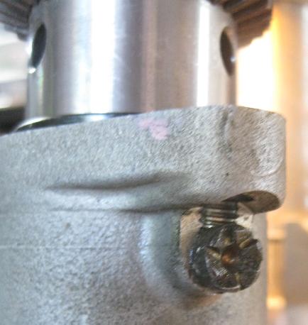
Back in 2011, our mortal Enemy in Virgina supplied the secret to brake switch removal and this pic of the interference problem.
Brake switch removal can confound even the advanced wrencher.
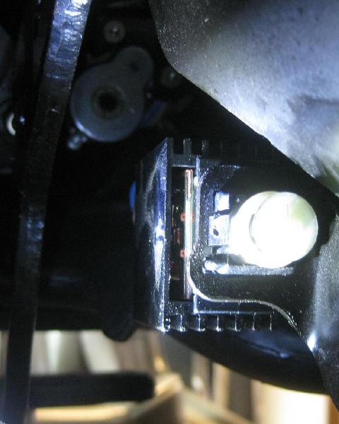
Problem 1 is that you can't get your eyeballs back there to see what holds the switch in. Therefore the following views were captured by remote camera positioning.
Note: There are definitely different switch styles and I would also suspect different mounting styles.
The switch as seen from the firewall.
Problem 2 is that even when you get your eyeball back there via digital camera, the release mechanism can stupify even a switchcraft master.
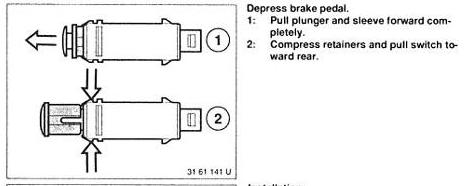
The adamant seeker will find the guarded secret in the ancient Tome of Maintenance.
Raid the Tome and scan the fading parchment for the word "completely". It's important.
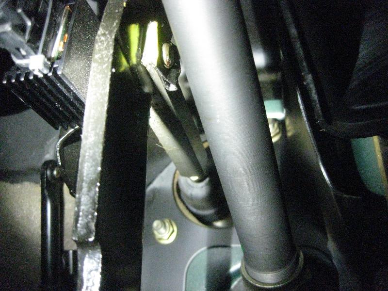
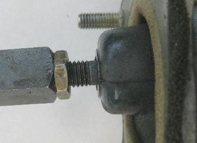
The plunger sleeve in its normal operating position.
Here the plunger and sleeve has been pulled forward to the insufficient middle position and the switch buggered out of the bracket anyway.
Further noodling about the tab release mechanism led me to discover that the plunger body can then be pulled out still further past some internal washboarding. Only then do the tabs depress properly.
Four bolts on the firewall are what hold the booster in place on the engine side. Nuts require a 13mm deep socket. An articulated ratchet extension is useful for the nut behind the steering column but an unnecessary fuss for the remaining three. The one wished-for equipment was a mountaineers headlamp instead of my flashlight. I see that there are also lighted reading glasses available. Nice.
**** On the bench ********
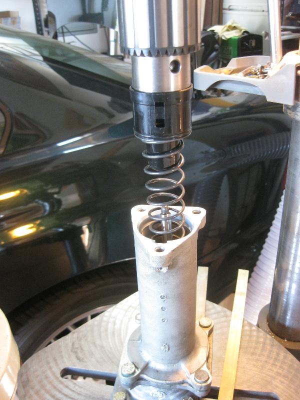
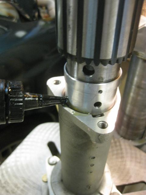
To deal with that unruly booster spring, the entire assembly was propped under a drill press arbor head, noting that my drill chuck more or less fit the size and shape of the spring retainer cone. The set screw was then removed.
and the drill press stage is cranked down revealing the spring, easily under control.
Note that although the booster will contain fluid, it should not leak out during this procedure unless you have rear seal problems to begin with.
After the actuator bar at the rear is unbolted, the remaining content of the bore are removed through the front. Remember your thread count.
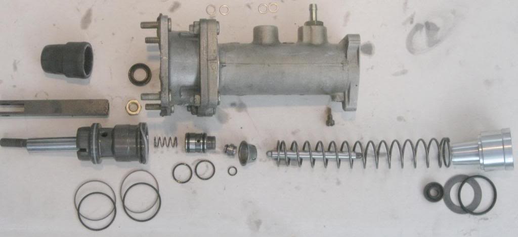
Here is my ultra-supremo contribution to H31 explosion pics, showing the pieces in their correct associations and orientation, along with the rebuild kit items approximately where they are used.
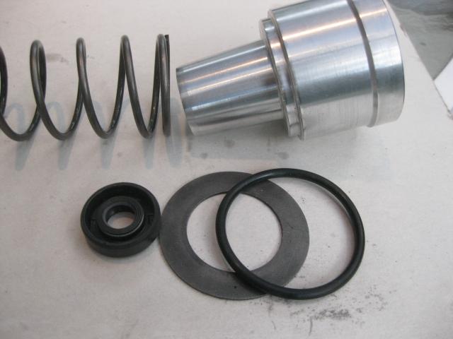
The front spring retainer cone, new from the all-inclusive version of the kit. The flat washer is reused original.
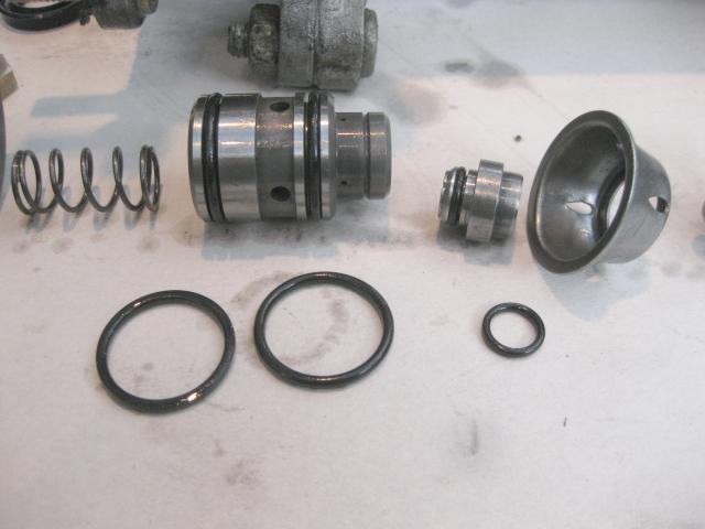
The middle pistons.
The larger piston on the left seemed to either bind in the bore or get stuck on edges. After o-ring replacement the operation was smoother, but not perfect. The new o-rings are pliant and larger than the originals (because they aren't yet shrunk and worn) and keep the piston centered in the bore and moving past edges.
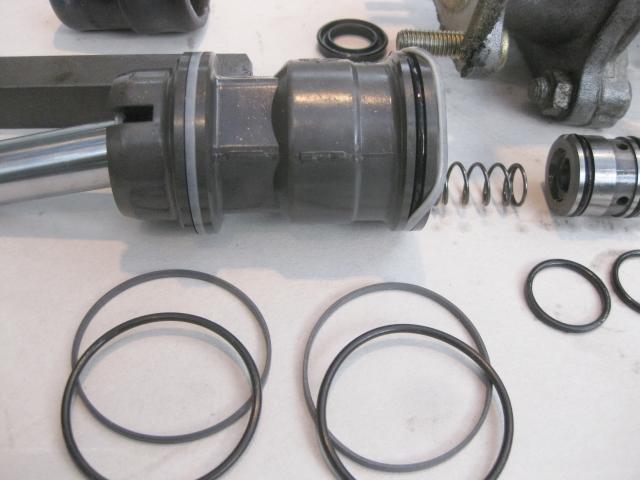
The rear piston, showing how the square-section band covers the rubber o-ring. The outer square-section rings are a challenge to install and there are two techniques to choose. I installed one by getting the entire circumference at once over the end bevel. This method risks ring breakage.
Looking for an easier safer solution on the second one, I depressed half of the circumference into the groove and firmly against the o-ring. This gave me enough slack to get the other half circumference over the bevel. This second method risks damage to the inside edges of the square-section.
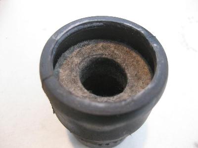
Fyi, the rear dust cover contains a felt plug. Mine was dry, consistent with no fluid leakage into the footwell from the original rear high pressure seal.
The rear seal is extracted using a hooked pick and patience
noting that the flat surface of the U-section is oriented to the rear.
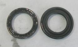
As Max will tell you, the rear seal provide in the kit is noticably larger/beefier than the seal it replaces
but it can still be stuffed back in.
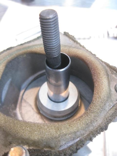
After replacing the other o-rings onto the rear and middle pistons and the front spring retainer cone the body is loaded back up. The square-section bands on the rear piston required a (very) light tap-in to get started, but after that the pistons could be shoved back with only finger pressure.
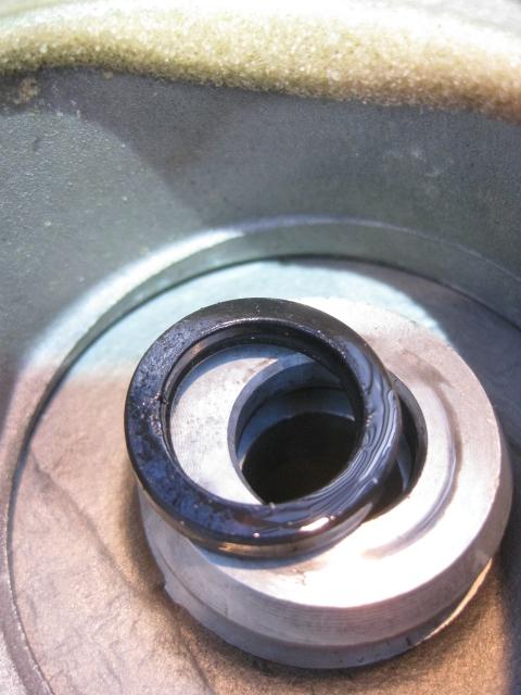
However, eventually the rear shaft will meet up with the new beefy rear seal. Imo, forcing the issue with a vise or press would damage the seal. Instead, use a pick or tiny blade to help the rear seal lip around the end of the input shaft tube, seen as the tiny sliver in the rear bore after this process was just started. After managing the seal lip over the tube end, you can then continue, either pushing the pistons or pulling on the input shaft
until the internals are in their final position in the bore.
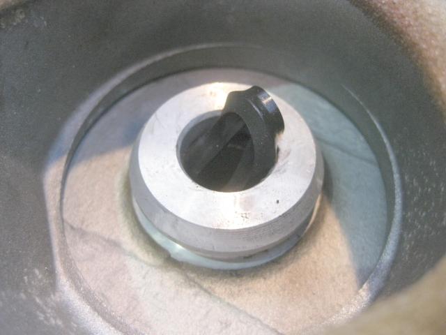
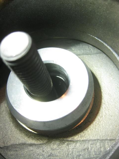
The assembly is then put back under the drill press head, with the retainer cone rotation is aligned to receive the set screw. The press stage is then cranked back up until the retainer cone o-ring enters the body. Note the application of lubricant at this point.
The final amount of travel is done by lowering the drill head arbor.
The cone o-ring easily slipped past the bore edge.
The cone traveled smoothly in either direction and the spring force was well within the range normally applied by the arbor during drilling ops.
Last edited by Hyper; 08-09-2017 at 11:45 PM. Reason: Pic link repair, re PB
I think I 8 too much
Wow, great write up and pics. Sure wish I had this when I did mine this last year. FWIW, my 850 has the three bolt connection between the master and booster cylinders too.
Member
Thanks. I'll adjust the writeup.Originally Posted by smc850ci

The online cat shows two servo PNs grouped as follows:
* e32/750, 850/M70, CSi
* 850/M73, 840
Member
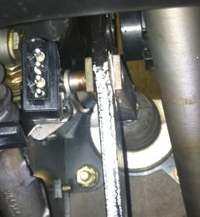
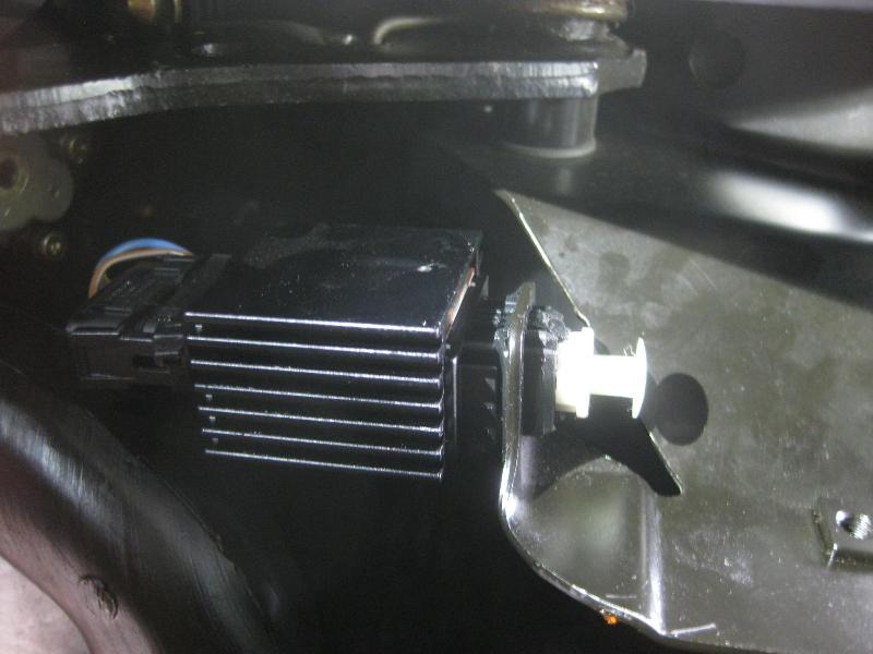
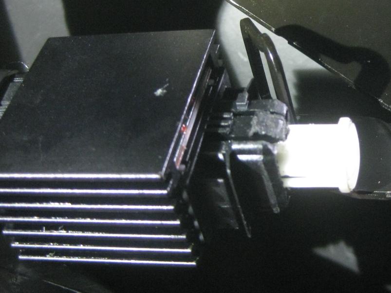
I just finished yanking my brake booster and couldn't have done it without this post and the ones Hyper referenced. It is remarkably complete, but I can add a couple of hints relevant to 840's and maybe others. First, a note about engine side access. It is not too bad. The master cylinder does not need to be disconnected. Similarly, the heater valves can be moved aside once the cabin air filter housing is removed. Once free, the booster hangs up on its hard line. Pull the coil cover off the engine to get enough clearance. Second, the fittings on the engine side suck. I partially stripped out a master cylinder bolt. Mine are 6mm allen head with yellow paint, and I've had the car long enough to know that is how it came from the factory. I got room to swing a flare wrench on the booster hard line by removing the nipple in front of it. Alas, it was no use as my flare wrench kept riding up, threatening to strip the fitting. I found a cheap set of metric flare crow's feet at Harbor Freight that did the trick. Finally, the infamous brake switch turned out to be a non-issue because of this post. I zip tied the brake pedal to the firewall, pulled the switch plunger with a trim remover until it hit the plate on the brake pedal, then used the same tool to pop the plunger sleeve completely out. There are two tabs at 9:00 and 3:00 that I depressed with bent nose pliers. It took me about 5 minutes to disconnect the brake pedal, most of which was spent figuring out what to depress on the switch because you can see absolutely nothing. Here's a picture showing the tabs that need to be depressed:
20171222_143238.jpg
Now my booster is off to Jay Stratton (Master6) for rebuild. It will be nice to have no more Pentosin puddle.
Brett
Member
Hi Brett,
I just noticed your post,
I do not get over to this blog very often,
I remember doing your 840 booster rebuild around Christmas a year ago.
Here is the link to my 16 websites, see # 1 for brake boosters
LINK : https://www.bimmerforums.com/forum/s...rrent-websites
Best,
Jay
Jay
'88 M6 Cinnabar Red / Nappa Natur Highline Interior (10-87) Santa Ana, California. USA
My NEW Website, Link : https://www.jaysbmwparts.com
Booster repair
https://www.jaysbmwparts.com
A/C Wingcell Compressor leak repair
https://www.jaysbmwparts.com
e31 Door Handle Fix,
https://www.jaysbmwparts.com
Member
I had a similar thing on my 840 quite a few years ago. Somewhere in a post there is a part number for the "O" ring from Napa. That was all I needed. I haven't had a leak since. I still have Max's rebuild kit for the next time. The drill press idea is priceless. I made a contraption to let the piston out but the drill press will be so much easier.
Member
The part number for the NAPA "O" ring is 727-2222. They are $.89 each. This should seal between the booster and the Master Cylinder. Not to rebuild, but to stop a fluid leak.
Member
Hi Richard,
I read your post about 5 years ago, and I copied your photo of the drill press idea,
onto my website DIY Tutorial.
Where Max and I differ, is that I think he charges too much for o-rings, and I also sell kits for less, but unlike Max, I personally do Booster rebuilds for clients.
I even have spare boosters if a client has a DD (daily driver), or uses a mechanic.
I also offer many other rebuilds, from PSP's to A/C compressors and Power Steering Gear Box leak repair. For Audi's and Bimmers.
Jay
Jay
'88 M6 Cinnabar Red / Nappa Natur Highline Interior (10-87) Santa Ana, California. USA
My NEW Website, Link : https://www.jaysbmwparts.com
Booster repair
https://www.jaysbmwparts.com
A/C Wingcell Compressor leak repair
https://www.jaysbmwparts.com
e31 Door Handle Fix,
https://www.jaysbmwparts.com
Member
Richard,
Yes that o-ring is available thru even Ace Hardware, if you know the size is 3x38
But the problem is that all of the o-rings, over 20 years old, the rubber has lost it elasticity, and is now hard, and has a "set" were the cross section is now oval or egg shaped.
And the height and width have changed their sizes, by to 20-25%.
So the next Booster leak will drip or squirt into the drivers footwell and stink up the carpet with either ATF or Petrosin.
Because you only fixed half of the problem.
This same thing is occurring in all components that have o-rings and shaft seals, anything made of rubber. That is why I repair so many components.
Best,
Jay
'88 M6 Cinnabar Red / Nappa Natur Highline Interior (10-87) Santa Ana, California. USA
My NEW Website, Link : https://www.jaysbmwparts.com
Booster repair
https://www.jaysbmwparts.com
A/C Wingcell Compressor leak repair
https://www.jaysbmwparts.com
e31 Door Handle Fix,
https://www.jaysbmwparts.com
 Posting Permissions


 Reply With Quote
Bookmarks