
 Moderator
Moderator
Moderator
Update to add DIY links for removal:
http://www.bimmerboard.com/forums/posts/45351
http://www.wibimmers.com/board/index.php?/topic/1389-e38-blower-motor-diy/
Edit to add fix for blower:
https://www.bimmerforums.com/forum/s...2#post30066222
Just changed mine out. There is a good DIY with pics already so that is not what this thread is about. I took pictures of the wiring going to the motor/resistor and found there is a place to access the wires after it leaves the relay. This would provide a testing point to see if voltage is leaving the relay. This would rule out fuses/relay and control panel.
Here you can see the where the wiring goes. You can see it leaving the blower motor in the upper left of the pic. There is a connection point where my finger is. You cannot access this without the dash off. If you look just below there you see the wires drop down and then go into the harness. This is where you can access them with just a little work:
With the glove box open, remove the three screws that hold the small panel to the dash. With it down, the wires will be in the far upper left area. You can see the yellow one in that area in this pic:
This is a closer view. At this point I have everything put back together except the panel piece above the open glove box.
Yellow wire - 12VDC (11.57)
Brown wire - 0 - the negative - ground
Red/grey little wire - from either 0.25VDC when the motor is supposed to be off, varying with the fan speed control up to about 7VDC.
E38's up to 09/96:
Blower relay:
K4, X58
behind glove box
K4 Blower relay X58 Component connector (9-pin, black), Blower relay
Blower relay power comes from Fuse 32 thru 09/96.
Control Panel (IHKA) = Fuse 20
Compressor = Fuse 11
K4 Blower relay
Connector overview
Pin assignments at connector X58
Number X-pin, color Description X58 9 -pin, Black Connector Blower relay
Pin Type Description / Signal type Connection /
Measuring notes1 Not used 2 E Terminal 30 voltage supply Fuse F32 3 Not used 4 E Relay control Blower relay Heating and A/C control module 5 Not used 6 A Component power (terminal 15) Blower switch IHKR Final stage unit IHKA 7 Not used 8 M Ground Ground splice 9 Not used
58 Component connector (9 -pin, black)
IHKA (Control Module)
A11
center console
A11 Heating and A/C control module IHKA
11 Heating and A/C control module IHKA
Connector overview
Pin assignments at connector 0 X18341
Number X-number of pins Description X18341 3 Heating and A/C control module Connector 0 X614 3 Heating and A/C control module Connector 1 X613 3 Heating and A/C control module Connector 2 X610 26 Heating and A/C control module Connector 3 X611 18 Heating and A/C control module Connector 4 X18153 3 Heating and A/C control module Connector 5
Pin assignments at connector 2 X614
Pin Type Description / Signal type Connection /
Measuring notes1 A Magnetic clutch voltage supply High pressure switch 2 E Terminal 30 voltage supply Fuse F11 Check this if compressor not running. ***** 3 M Ground Ground point
Pin assignments at connector 1 X613
Pin Type Description / Signal type Connection /
Measuring notes1 A Control voltage Right actuator motors and defrosting 2 M Actuator motors ground Right actuator motors and defrosting 3 E/A MI-bus Right actuator motors and defrosting
Pin assignments at connector 3 X610
Pin Type Description / Signal type Connection /
Measuring notes1 A Control voltage Left actuator motors and recirculated air 2 M Actuator motors ground Left actuator motors and recirculated air 3 E/A MI-bus Left actuator motors and recirculated air
Pin assignments at connector 4 X611
Pin Type Description / Signal type Connection /
Measuring notes1 E Voltage supply, terminal 15 Fuse F20 Battery voltage 2 E Compressor ON signal from engine control module (DME) Engine control module (DME)DDE control module 3 A A/C compressor signal to engine control module (DME) Engine control module (DME)DDE control module 4 A A/C standby signal to engine control module (DME) Engine control module (DME) 728i, 730i, 735i, 740iDDE control module 725tds A/C splice 750i 5 A Rear window defogger relay control Rear defogger relay 6 A Front defogger/washer jets relay control Front defogger/washer jets relay 7 Not used 8 A Blower control voltage Final stage unit 9 Not used 10 M Circulation (AUC) heater component ground Automatic air recirculation sensor 11 Not used 12 E Consumer cut-off signal General module 13 Not used 14 A Auxiliary water pump control Auxiliary water pump 15 A Blower relay control Blower relay 16 Not used 17 A Auxiliary fan normal speed relay control Auxiliary fan normal speed relay 18 E Nighttime illumination signal Light module 19 E/A K-bus signal line K-bus splice 20 A Left water valve control Water valve assembly, Left valve 21 A Right water valve control Water valve assembly, Right valve 22 Not used 23 A Sensor voltage supply Automatic air recirculation sensor 24 E Sensors Automatic air recirculation sensor 25 A Circulation (AUC) heating control Automatic air recirculation sensor 26 Not used
Pin assignments at connector 5 X18153
Pin Type Description / Signal type Connection /
Measuring notes1 E Actuating signal Fresh air flap motor 2 A Actuating signal Fresh air flap motor 3 A Actuating signal Fresh air flap motor 4 E Actuating signal Fresh air flap motor 5 E Mixing air actuator desired value Rear mixing actuator 6 A Sensors (+) Mixing actuator / Rear mixing actuator 7 E Mixing air actuator desired value Mixing actuator 8 E Sensor signal Right ventilation sensor 9 E Sensor signal Left ventilation sensor 10 E Ventilation ON signal Rear ventilation switch 11 Not used 12 Not used 13 Not used 14 M Component ground Sensor and actuator 15 E Sensor signal Evaporator temperature sensor 16 E Sensor signal RH heat exchanger temperature sensor 17 E Sensor signal LH heat exchanger temperature sensor 18 Not used
Pin Type Description / Signal type Connection /
Measuring notes1 A Park heating ON signal up to 08/1995 Park heating/ventilation control module as of 09/1995 Receiver, independent heating 2 A Control voltage Solenoid valve 2 park heating/ventilation 3 E Park heating ON feedback signal Park heating/ventilation control module
This is your plug at the blower motor but if you made it this far, you probably already know it's the blower/resistor.
X671 Component connector (5 -pin, black)
N2 Final stage unit
Connector overview
Pin assignments at connector X671
Number X-pin, color Description X671 5 -pin, Black Connector Final stage unit X816 2 -pin, Black Connector Final stage unit
Pin assignments at connector X816
Pin Type Description / Signal type Connection /
Measuring notes1 E Component power (terminal 15) Blower relay 2 Not used 3 E Signal Final stage unit Heating and A/C control module 4 M Ground Ground splice 5 Not used
Pin Type Description / Signal type Connection /
Measuring notes1 M Ground Blower motor 2 E Voltage control Blower motor Blower motor
================================================== =======================
From 09/96 to 09/98:
Much of this information will be the same. One notable change is Fuse 81 below.
* Fuses – The blower motor is powered by a series of fuses, a relay and the final stage unit (and, of course, the
control panel)
* Fuse # F100 in the High-Amp fuse panel (located in right side of trunk, ahead of battery)
* Fuse # F113 in the passenger side floor panel (under right-front seat)
* Fuse # F81 in the engine compartment E-Box (right-rear of engine compartment)
* Relay # K4 in relay panel forward of the glovebox
* Final Stage Unit is mounted to the motor itself
F81, X10298
rear RH side of engine compartment in electronics box
F81 Fuse F81 X10298 Cable shoe Fuse F81
K4 Relay info from 1997 740iL with pics in this thread:
http://forums.bimmerforums.com/forum...fying-relay-K4
K4 Blower relay
Connector overview
Pin assignments at connector X58
Number X-pin, color Description X58 9-pin, Black Connector Blower relay
Pin Type Description / Signal type Connection /
Measuring notes1 Not used 2 E Terminal 30 voltage supply Fuse, officials utility vehicle F02 3 Not used 4 E Relay control Blower relay Heating and A/C control module 5 Not used 6 A Component power (terminal 15) Blower switch IHKR N2 IHKA 7 Not used 8 M Ground Ground splice 9 Not used
Appears there is some differences at the control module, probably due to the 'MAX' feature. As I am not clear on it just yet, I will refrain from addressing it. I don't believe it would come into play with a non working blowing.
Done for now. Feel free to ask questions. I know this is a little overkill on the blower issue but may come in handy for other HVAC problems.
Last edited by Mayorchuck; 07-17-2018 at 12:11 PM. Reason: Add Fuse/Relay info
Moderator
Moderator
Fuse 20 powers the IKHA (Control Module) for all E38's.
Fuse 11 supplies the compressor.
NOTE: This link suggest the WDS is wrong from this model forward in that there is no K4 relay:
http://www.bimmerboard.com/forums/posts/823547
IHKA for E38's from 09/98 to 03/2000
A11
centre console
A11 Heating and A/C control module IHKA
11 Heating and A/C control module
Plug connector overview
Pin assignments at plug connector X610
Number X-pin, colour Description X610 26-pin, blue Plug connector 3 Heating and A/C control module X611 18-pin, natural Plug connector 4 Heating and A/C control module X613 3-pin, natural Plug connector 2 Heating and A/C control module X614 3-pin, black Plug connector Heating and A/C control module X18153 3-pin, black Plug connector 5 Heating and A/C control module X18341 3-pin, black Plug connector 0 Heating and A/C control module
Pin assignments at plug connector X611
Pin Type Description / Signal type Connection /
Measuring notes1 E Voltage supply, terminal 15 Fuse F20 2 A Signal, A/C compressor OFF (M51) A/C compressor signal DDE control unit DME control unit Digital diesel electronics control unit 3 A Signal, A/C compressor ON (M51) DDE control unit 4 A Air conditioning system standby signal DDE control unit 5 A Relay activation, rear window defogger Rear defogger relay 6 A Relay activation, windscreen/spray jet heating Heated front screen/washer jets relay 7 E Pressure signal High pressure switch 8 A Blower control voltage Output stage 9 Not used 10 M Component ground, AUC heating AUC sensor 11 M Ground High pressure switch High pressure switch 12 E Signal, switch off consumer load General module 13 Not used 14 A Auxiliary water pump activation Auxiliary water pump 15 A Relay activation, blower unloader relay Heating blower relay 16 Not used 17 A Relay activation, auxiliary fan stage I Auxiliary fan stage 1 relay 18 E Night light signal Connector, terminal 58g 19 E/A K-bus signal line K-bus connector 20 A Left water valve activation Water valves, Left valve 21 A Right water valve activation Water valves, Right valve 22 A Supply High pressure switch High pressure switch 23 A Sensor positive supply AUC sensor 24 E Negative activation AUC sensor 25 A Positive supply, AUC heating AUC sensor 26 Not used
Pin assignments at plug connector X613
Pin Type Description / Signal type Connection /
Measuring notes1 E Actuating signal Fresh air flap motor 2 A Actuating signal Fresh air flap motor 3 A Actuating signal Fresh air flap motor 4 E Actuating signal Fresh air flap motor 5 E Setpoint, mixing air actuator Rear mixing air actuator 6 A Sensors (+) Temperature distribution potentiometer, Rear mixing air actuator 7 E Setpoint, mixing air actuator Temperature distribution potentiometer 8 E Sensor signal Right ventilation sensor 9 E Sensor signal Left ventilation sensor 10 E Signal, ventilation ON Rear passenger compartment ventilation switch 11 Not used 12 Not used 13 Not used 14 M Component ground Sensor and actuator 15 E Sensor signal Evaporator sensor 16 E Sensor signal Right heat exchanger sensor 17 E Sensor signal Left heat exchanger sensor 18 Not used
Pin assignments at plug connector X614
Pin Type Description / Signal type Connection /
Measuring notes1 A Control voltage Left actuator motors and recirculated air 2 M Ground, actuator motors Left actuator motors and recirculated air 3 E/A MI-bus Left actuator motors and recirculated air
Pin assignments at plug connector X18153
Pin Type Description / Signal type Connection /
Measuring notes1 A Control voltage Right actuator motors and defrosting 2 M Ground, actuator motors Right actuator motors and defrosting 3 E/A MI-bus Right actuator motors and defrosting
Pin assignments at plug connector X18341
Pin Type Description / Signal type Connection /
Measuring notes1 A Signal, independent heating ON up to 1995_08 Independent park/auxiliary heating as of 1995_09 Receiver, independent heating 2 A Control voltage Solenoid valve independent heating/ventilation II 3 E Independent heating ON feedback Independent park/auxiliary heating
Pin Type Description / Signal type Connection /
Measuring notes1 A Positive supply, magnetic clutch High pressure switch (M51) Heating and A/C control module 2 E Voltage supply terminal 30 Fuse F11 (Compressor) 3 M Ground Ground connection X492
This is from 03/2000 to end of production.
The difference it slight but it's there.
11 Heating and A/C control module
Plug connector overview
Pin assignments at plug connector X610
Number X-pin, colour Description X610 26-pin, blue Plug connector 3 Heating and A/C control module X611 18-pin, white Plug connector 4 Heating and A/C control module X613 3-pin, natural Plug connector 2 Heating and A/C control module X614 3-pin, black Plug connector Heating and A/C control module X18153 3-pin, black Plug connector 5 Heating and A/C control module X18341 3-pin, black Plug connector 0 Heating and A/C control module
Pin assignments at plug connector X611
Pin Type Description / Signal type Connection /
Measuring notes1 E Voltage supply, terminal 15 Fuse F20 2 A Signal, A/C compressor OFF (M51) A/C compressor signal DDE control unit DME control unit Digital diesel electronics control unit 3 A Signal, A/C compressor ON (M51) DDE control unit 4 A Air conditioning system standby signal DDE control unit 5 A Relay activation, rear window defogger Rear defogger relay 6 A Relay activation, windscreen/spray jet heating Heated front screen/washer jets relay 7 E Pressure signal High pressure switch 8 A Blower control voltage Output stage 9 Not used 10 M Component ground, AUC heating AUC sensor 11 M Ground High pressure switch High pressure switch 12 E Signal, switch off consumer load General module 13 Not used 14 A Auxiliary water pump activation Auxiliary water pump 15 A Relay activation, blower unloader relay Heating blower relay 16 Not used 17 A Relay activation, auxiliary fan stage I Auxiliary fan stage 1 relay 18 E Night light signal Connector, terminal 58g 19 E/A K-bus signal line K-bus connector 20 A Left water valve activation Water valves, Left valve 21 A Right water valve activation Water valves, Right valve 22 A Supply High pressure switch High pressure switch 23 A Sensor positive supply AUC sensor 24 E Negative activation AUC sensor 25 A Positive supply, AUC heating AUC sensor 26 Not used
Pin assignments at plug connector X613
Pin Type Description / Signal type Connection /
Measuring notes1 E Actuating signal Fresh air flap motor 2 A Actuating signal Fresh air flap motor 3 A Actuating signal Fresh air flap motor 4 E Actuating signal Fresh air flap motor 5 E Setpoint, mixing air actuator Rear mixing air actuator 6 A Sensors (+) Temperature distribution potentiometer, Rear mixing air actuator 7 E Setpoint, mixing air actuator Temperature distribution potentiometer 8 E Sensor signal Right ventilation sensor 9 E Sensor signal Left ventilation sensor 10 E Signal, ventilation ON Rear passenger compartment ventilation switch 11 E Signal input Solar sensor with DWA LED 12 E Signal input Solar sensor with DWA LED 13 A Component supply Solar sensor with DWA LED 14 M Component ground Sensor and actuator 15 E Sensor signal Evaporator sensor 16 E Sensor signal Right heat exchanger sensor 17 E Sensor signal Left heat exchanger sensor 18 M Component ground Solar sensor with DWA LED
Pin assignments at plug connector X614
Pin Type Description / Signal type Connection /
Measuring notes1 A Control voltage Left actuator motors and recirculated air 2 M Ground, actuator motors Left actuator motors and recirculated air 3 E/A MI-bus Left actuator motors and recirculated air
Pin assignments at plug connector X18153
Pin Type Description / Signal type Connection /
Measuring notes1 A Control voltage Right actuator motors and defrosting 2 M Ground, actuator motors Right actuator motors and defrosting 3 E/A MI-bus Right actuator motors and defrosting
Pin assignments at plug connector X18341
Pin Type Description / Signal type Connection /
Measuring notes1 Not used 2 A Control voltage Solenoid valve independent heating/ventilation II 3 E Independent heating ON feedback Independent park/auxiliary heating
Pin Type Description / Signal type Connection /
Measuring notes1 A Positive supply, magnetic clutch High pressure switch (M51) Heating and A/C control module 2 E Voltage supply terminal 30 Fuse F11 (Compressor) 3 M Ground Ground connection X492
- - - Updated - - -
http://www.bmw-planet.com/diagrams/r...8new/index.htm
I will be adding schematics as well. You can go to the WDS and put any of the green letters/numbers in the search box to get detailed info.
This is the overall schematic for the air conditioning system, 09/98 and up.
NOTE: Please read info in this link concerning the blower relay, K4
http://www.bimmerboard.com/forums/posts/823547
Here is the info for the blower motor for 09/98 and up. Notice that Fuse 81 mentioned earlier now comes into play. A11 is listed by models above. This is the control module in the console. There are not two of them. This is just showing you that on connector x610, the 26 pin blue connector, that Pin 8 goes to the output stage which is the resistor on the blower motor. Pin 15 from the same connector goes to the relay.
UPDATE: Please see info in link below concerning blower relay, K4
http://www.bimmerboard.com/forums/posts/823547

Last edited by Mayorchuck; 08-02-2013 at 05:15 PM.
meeknet.co.uk
Great information, it is little snippets of information like this that becomes very important when you have blower problems!
Timm..2007 E64 650i Individual Sport..1999 E31 840ci Individual Sport..ex owner of 2000 E38 740..1999 E38 740i V8 M62..1998 E38 735i V8..1993 E32 730i V8..1988 E28 518i
My BMW Repair YouTube Channel
My Current 840ci Sport Individual
My Current 650ci Sport Individual
My E31 Repair and Information Website
My E38 Repair and Information Website
My E63/E64 Repair and Information Website
Chase - Heroes to a generation
Moderator
Moderator
It's no Meeknet but hopefully it will come in handy with blower and other a/c issues. At least it will be a place where I can refer to without having to go thru the WDS each time.
¿pǝpɹɐʇǝɹ noʎ ǝɹɐ
Whats the fun in that?Originally Posted by Mayorchuck

95 840Ci, Calypso Red/Silver, 83k - 99 740i, Black/Black, 185k, Alpina Mods - 01 740i, Titanium/Silver, 40k, Sport Pkg
Complete Turnkey Diagnostic/Programming systems available...PM for details.
http://www.8Coupe.com - Please register, spot, and help the project.
Moderator
Moderator
Blower running with little to no air flow:
While not as common, a recent thread with limited air flow that was not caused by recirculation filters:
http://forums.bimmerforums.com/forum....php?t=2005343
http://www.magnum1.com/magnum/BMW-74...uators-740.php
Moderator
Moderator
A/C info added for later editing:
Air conditioning
The air conditioning system is switched on by pressing the air conditioning button. The function light signals that the air conditioning system is in standby mode.
The compressor only cuts in if the switch-on conditions are fulfilled. The evaporator then produces cold air which is raised to the required temperature in reheat mode with the aid of the heat exchanger.
To protect the evaporator from icing up, the outlet temperature is monitored by means of a sensor (evaporator sensor) and the compressor is controlled by means of an electromagnetic clutch.
If a mechanically controlled compressor is installed, the evaporator cutout temperature is dependent on the outside temperature. If the outside temperature increases above 20 degrees Celsius the cutout temperature drops to 1 degrees Celsius.
The control unit output DME_KO is used to transfer the switch-on signal of the controlled compressor to the DME. The individual switching stages are transferred by way of pulse width modulation with a frequency of 5 Hz.
Diagnosis of the line is carried out by the DME.
Pulse duty factor in % Functions Short to U-batt. or line break 15 Air conditioning off 30 Air conditioning standby (DME_AC) ON 45 A/C compressor ON, stage 1 = 5-10 Nm 60 A/C compressor ON, stage 2 = 10-15 Nm 75 A/C compressor ON, stage 3 = 15-20 Nm 90 A/C compressor ON, stage 4 = 20-24 Nm 100 Short to ground
Switching conditions for the electromagnetic clutch
Pressure switch
ON (all conditions must be fulfilled) OFF (one of the conditions must be fulfilled) Timed mode (switching on and off in 20 s clock cycle) Terminal 15 ON Terminal 15 OFF Coolant temperature greater than 117 o C and less than 120 o C Air flow control wheeldriver out of zero position Air flow control wheeldriver in zero position Air conditioning standby ON (function light ON) Air conditioning standby OFF (function light OFF) Evaporator temperature > 3 o C Evaporator temperature < 2 o C Coolant temperature < 117 o C Coolant temperature > 120 o C - 3 o C hysteresis Air conditioning system signal sent from DME (compressor ON) Full throttle signal from DME initiates shut-down with respect to time Delay time 5 s (on reaching engine speed > 600 rpm) elapsed Speed dropped below minimum value (400 rpm)
The triple pressure switch opens the power circuit to the electromagnetic clutch when the refrigerant pressure drops below the value set for low pressure or exceeds the value set for high pressure.
Evaporator control
Low pressure Medium pressure High pressure ON < 2.8 +/- 0.2 bar ON > 20.0 +/- 1 bar ON > 33.0 +/- 1 bar OFF >1.9 +/- 0.2 bar OFF < 17.5 +/- 1 bar OFF < 23.5 +/- 1 bar
The evaporator temperature controller is made up of a two-point controller on the basis of a variable positive switching threshold with 1 o K hysteresis. The refrigeration circuit is activated at an evaporator temperature > 3 o C and deactivated at an evaporator temperature < 2 o C. This function prevents the evaporator from icing up.
Coolant temperature
The instrument cluster electronics (IKE) features a coolant sensor on the radiator circuit. This analog sensor signal is processed in the IKE and read in by the IHKR via the K-bus.
To avoid the engine overheating, the cooling water is monitored by the air conditioning system. At a coolant temperature above 117 o C, the electromagnetic clutch is switched on and off at 20 s intervals. If the coolant temperature exceeds 120 o C, the electromagnetic switch is switched off until the temperature drops below 117 o C. The electromagnetic clutch then cuts in once again at a rate of 100%.
Full load cutout
In order to shorten the rev-up time of the engine from idle up to full load, the electromagnetic clutch is switched off for a limited period of time at full throttle. The cutout time is between 7 and 10 s depending on the type of engine.
Full load condition: Speed signal < 14 km/h and acceleration
Idle increase (anti-stall)
To ensure smooth operation is not impaired by the compressor load, the control lines AC and KO are provided for activation of the DME by the air conditioning control unit.
When the air conditioning system is switched on, the air conditioning control unit output AC requests an idle increase from the DME. When the signal is active, the DME increases the idle speed by 110 - 200 rpm irrespective of the electromagnetic clutch.
The idle increase function (anti-stall) is additionally possible by means of coding.
Option 1: After switching on the rear window defogger, the blower in maximum setting, low beam or high beam.
Option 2: When undervoltage detected. The idle increase function is activated at terminal 30 < 11.4 V and deactivated at terminal 30 > 12.2 V.
Compressor activation
The air conditioning function is activated by pressing the A/C button. This is followed by idle increase. By way of the output KO, the air conditioning control unit informs the DME that it intends to switch on the compressor. Consequently, the DME implements an interfering variable circuit, i.e. it moves the throttle in the direction "more air" while at the same time increasing the injection quantity.
By way of the KOREL signal (compressor relay), the DME sends a feedback message to the air conditioning control unit instructing it to switch on the A/C compressor. If all conditions for switching on the A/C compressor are fulfilled, the A/C compressor is activated directly by the control unit.
To avoid excessive water discharge from the evaporator, after the air conditioning system has been switched off while driving, the compressor is switched on and off at set intervals for 15 minutes. In this way, the evaporator temperature is slowly brought to the value of the outside temperature.
Auxiliary fan stage 1
The air conditioning system cuts in stage 1 of the auxiliary fan by means of relays when the compressor clutch is active and the outside temperature is greater than 10 o C. The auxiliary fan cuts out when the compressor clutch has switched off or the outside temperature is less than 8 o C.
For safety reasons, a thermostat switch also causes stage 1 to cut in at a temperature of 91 o C irrespective of the instruction given by the air conditioning control unit.
Auxiliary fan stage 2
Stage 2 of the auxiliary fan is not cut in by the air conditioning control unit.
If the cooling water exceeds a value above 99 o C or if the medium pressure switch has closed, stage 2 cuts in by means of a relay.
Moderator
Moderator
Air distribution
Air distribution programs
In addition to the automatic air distribution program, the driver has available three and the passenger two manual air distribution programs. They are used to open and close the ventilation and footwell flaps independent from each other and separately on the driver's and passenger's side and independent of the set temperature value. For safety reasons, operation of the defrost function on the driver's and passenger's side is reserved for the driver.
With the aid of these programs, cooled air can be blown out of the defroster and footwell ducts in A/C mode and warm air can be blown out of the ventilation grilles in winter mode.
In this way situations are covered in which the automatic program no longer fulfils the set requirements.
Actuator drives
10 electrical actuator drives are installed in the system to provide infinitely variable operation of the air outlet flaps during automatic climate control (IHKA). They consist of stepper motors and step-down gear systems.
A stepper motor driven via 4 lines operates the fresh air flaps. New bus-controlled motors are used to operate all other flaps. Each of these motors features its own electronic circuitry and is electrically coded, i.e. the motor must be installed in its intended position.
Note
Each of these motors features its own electronic circuitry and is electrically coded, i.e. the motor must be installed on its own specific flap.
The design of several components in the electronic circuitry of the motors has made it possible to reduce the size of the control electronics to such an extent that it can be housed in the operating unit. An additional control unit is therefore no longer necessary.
A further advantage is that up to 5 motors are connected to a common 3-core lead (instead of the previous 6 connections per motor). Two motor variants with connector output are used on the electronics unit on the left or right.
Automatic recirculated air control (AUC)
The pollutant detector for the automatic recirculated air control system (AUC) is installed on the air inlet of the auxiliary fan. The evaluation electronics necessary for this sensor is integrated in the air conditioning control unit.
Start phase
The AUC function is activated by pressing the recirculated air/AUC button. The function light above the AUC symbol indicates the function is in standby mode.
When starting the vehicle, fresh air is always supplied for 90 seconds due to the AUC sensor heating-up time.
Generally in recirculated air mode, the relative humidity in the interior of the vehicle can increase due to the lack of fresh air. This results in condensation forming on the window. For this reason, the recirculated air status is limited in AUC mode dependent on heating or air conditioning operation.
- Time limit in heating mode: 3 minutes
- Time limit in air conditioning mode: 12 minutes
Once these times have elapsed, the air supply switches automatically back to outside air (fresh air flap open) for 1 minute. The AUC function is active once again after the minute has elapsed.
- - - Updated - - -
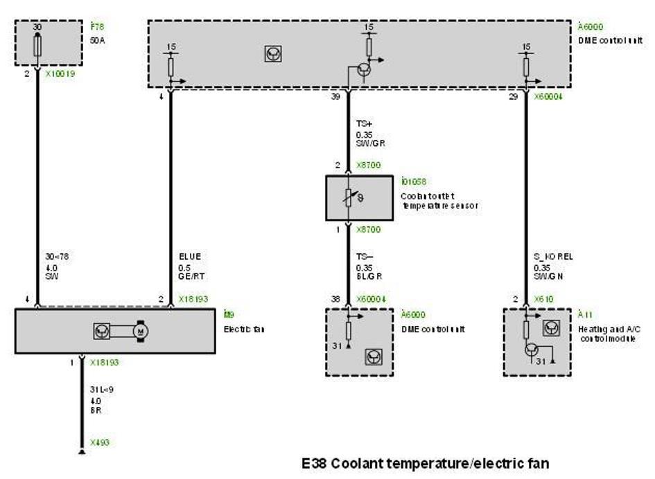
Electric Fan
Vehicles with M62TU, S62 and M73 engines feature a viscous fan as well as an electric fan. The electric fan cuts in when the cooling capacity of the viscous fan is no longer sufficient.
The electric fan is activated by means of a power output stage directly on the fan motor. The motor control unit activates this power output stage by means of a square-wave signal with duty factors (variable pulse width) between 10 % and 90 % thus controlling the various speeds of the electric fan. Pulse duty factors less than 5 % and greater than 95 % do not trigger activation but rather they are used for fault detection purposes. The power output stage features its own positive and ground supply.
The fan speed is influenced by the coolant temperature at the radiator outlet and the pressure in the air conditioning system. The fan speed is reduced as the vehicle speed increases.
If a fault occurs during operation a corresponding fault code will be stored in the fault code memory of the DME control unit.
For the purpose of checking operation and troubleshooting, the diagnostic program offers the option of activating the electric fan directly via the DIS tester/MoDiC.
Last edited by Mayorchuck; 05-21-2014 at 10:32 PM.
Member
Nicely done!
Member
Thanks for the input. I will look into testing via the "activating the electric fan directly via the DIS tester/MoDiC".
 Posting Permissions


 Reply With Quote


Bookmarks