
 Still has a E39
Supporting Vendor
Still has a E39
Supporting Vendor
Finally got around to making some AC lines for my pile. Started with the e39 and Camaro lines. Cut stuff so it looked like it would fit, then had a hose place up the street braze a couple fittings on. Havent decided how I'm going to trigger it yet, time will tell.

Last edited by M5Hunter; 07-30-2014 at 11:36 AM.
BMW + ASE Master Tech
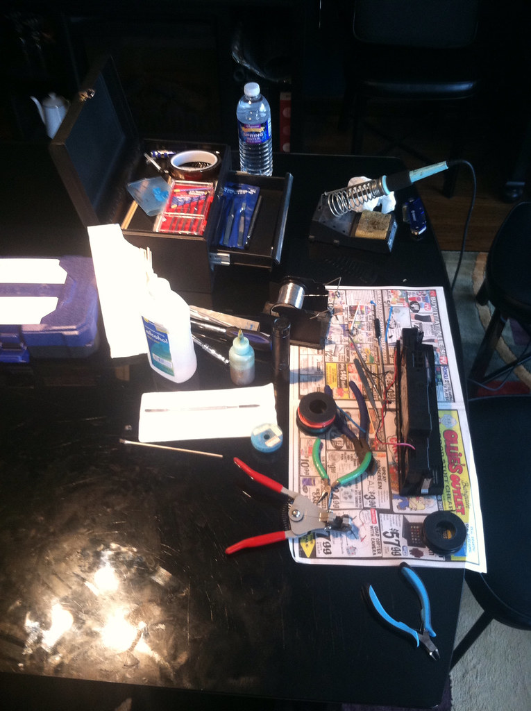
Just finished soldering up the relay setup like James' diagram.. It will be a super nice upgrade vs the cigarette lighter cord activating the a/c ( but it works!!)
2006 X5 L83 5.3 6l80 swapped in progress
1999 528i 5.7L 4l60e swapped w/ 31 spline 8.8 cobra diff
2007 ZX-10r - sold
1987 R-10 SWB L83 5.3L 6L80e swapped
Member
How has this been working out for you? I want to replicate the same setup. I don't like the idea of a rice-a-roni toggle switch to control output, and the CAN-BUS stuff seems like a pain.Originally Posted by modular93fox

This:
(http://www.bimmerforums.com/forum/sh...5#post26390785)
Last edited by nsogiba; 07-09-2015 at 09:55 AM.
BMW + ASE Master Tech
No so good.. Made the board just fine. took the ac panel apart and realized I didn't think I could do it... Got scared. Still using the cigarette lighter at the moment.
Edit-spell check lol
Last edited by modular93fox; 07-13-2015 at 10:58 PM.
2006 X5 L83 5.3 6l80 swapped in progress
1999 528i 5.7L 4l60e swapped w/ 31 spline 8.8 cobra diff
2007 ZX-10r - sold
1987 R-10 SWB L83 5.3L 6L80e swapped
Black Sheep
Ahhh! Common' man. The solder points across the LED are small, but it's nothing to be scared of.
'99 BMW 540i6 L33 5.3, PRC Heads, E-force supercharged
http://forums.bimmerforums.com/forum....php?t=1674320
Member
I am about half done soldering up the board using some old parts, it was easy enough. I had a spare junk IHKA in the basement that I took apart - boy those pins sure are small, Clint wasn't kidding. I'm probably going to have a local buddy do it who specializes in small circuitry.
Member
ok, I am somewhat confused on the functionality of the pressure switch/sensor, specific to a 2003 Express Van PCM. all the literature i've read on here and most other sites regarding LS swaps refers to just one pressure switch in the system, with a 3-wire connector. However, when I looked up the wiring diagram for HVAC for the '03 van, it calls out 2 pressure switches, a high and a low.
Diagram taken from Chilton manual on the local library website:
HVAC 03 Van by Norbert Ogiba, on Flickr
What gives? My head hurts from looking at wiring diagrams
Last edited by nsogiba; 08-08-2015 at 04:48 PM.
Member
Aren't you tapping the "a/c request" from the BMW effectively negating the need for the High Pressure Switch on that diagram?
BMW + ASE Master Tech
The system still should use at least te high pressure switch. The BMW side of things is nearly the on signal. That's all we want from the ihka.
2006 X5 L83 5.3 6l80 swapped in progress
1999 528i 5.7L 4l60e swapped w/ 31 spline 8.8 cobra diff
2007 ZX-10r - sold
1987 R-10 SWB L83 5.3L 6L80e swapped
Member
That's because you are using a van PCM. Your system has 2 switches, but yo already figured that out
The low switch prevents the PCM from turning the compressor on if the system is low on refrigerant and the high pressure switches off the compressor if the refrigerant pressure is too high. The good news is that odds are that since the van uses an old style system, the switch bungs are more likely the much easier to find variety.
Rob
Prior projects:
1998 540i with 6.6 LS2/T56 Chevy Power
- pictures and details
1992 325i with 6.6 LS2/T56 Chevy power - pictures and details
1995 M3 with 6.6 LS2/T56 Chevy power - pictures and details
Member
you would assume so...after I figured out that the Van uses 2 switches, I started looking at where in the system they were, so that I could find the type of bung they use, and then find out what kinds of other GM junk i could rob them out of. It appears that 99-02 trucks shared this same twin switch system with the Vans. Turns out the low pressure switch is mounted to the accumulator/drier itself
and the high pressure switch is on the back of the compressor. Hopefully these ports are the common Schrader valve type, I will try to confirm this weekend with a trip to the boneyard. i already had the BMW and GM lines grafted together, will post some pictures when I get a chance. I'd like to finish the lines completely and install them before tackling wiring.
BMW + ASE Master Tech
In my 5.3 swapped Silverado I simply grounded the circuits. That's what the switch does. Never got around to welding in a bung or installing the switches. Works fine... Just won't cut off if the pressure gets to high
2006 X5 L83 5.3 6l80 swapped in progress
1999 528i 5.7L 4l60e swapped w/ 31 spline 8.8 cobra diff
2007 ZX-10r - sold
1987 R-10 SWB L83 5.3L 6L80e swapped
Black Sheep
I don't have a low pressure switch, only a high. My swap was from an '04 truck, but I had the 12v AC request enabled on it (only certain truck PCM's would allow for the 12v A/C request "mod"), so I'd say you need both in your situation.
My switch definitely reads the pressure, as I can log the pressure reported by the sensor with my EFILive scanner.
Last edited by James39; 08-12-2015 at 10:41 PM.
'99 BMW 540i6 L33 5.3, PRC Heads, E-force supercharged
http://forums.bimmerforums.com/forum....php?t=1674320
Member
did the "Snowflake LED" mod
Just need to:
hook up the 12V input under the dash and run the signal wire to the PCM
wire all the GM crap (compressor, pressure switches)
figure out what kind of pressure switches to use and where
install lines
change out drier
charge system
Member
bump, i want to wrap up my A/C.
Here is my question:
^Above diagram was taken from a Chilton wiring diagram for a 2003 Express Van and calls for a high pressure switch, and a low pressure switch.
I am using a 2003 Express Van PCM and the LT1Swap Diagram for the 2004 Vortec that I used flawlessly to wire the whole swap calls for a 5V reference, a pressure SENSOR signal, and a low reference (omitting the Clutch relay control which obviously is similar between the two)
http://lt1swap.com/2004vortec_pcm.htm
However if I go back and look at the LT1swap site for a 99-02 truck, it's again calling for a high/low switch signal.
So the question: who's right? Is the '03 Van wired like a 99-02 truck, or like a 04+ Vortec (truck) ? I don't want to hook up the switch signals to the wrong pins on the PCM. Obviously there was a lot of changeover going on at GM at this time between the A/C pressure stuff as well as the DBC -> DBW changeover.
- - - Updated - - -
also, what's going on at pin 17 at C2? is it looking for A/C request signal or the high pressure switch signal?
Last edited by nsogiba; 12-01-2015 at 07:53 PM.
BMW + ASE Master Tech
I'll look at some more schematics later but that is the ac request signal that lets the PCM know to turn the compressor on... But the sensor is in between the circuit. But this is for a 02 style Silverado PCM maybe the same
2006 X5 L83 5.3 6l80 swapped in progress
1999 528i 5.7L 4l60e swapped w/ 31 spline 8.8 cobra diff
2007 ZX-10r - sold
1987 R-10 SWB L83 5.3L 6L80e swapped
Major Lazer
Trucks of that era used either the High/Low switches as seen on the Chilton schematic or a pressure traducer (has 3 pins: low ref, 5V ref, and signal) as referenced in the LT1Swap pinout.
C2 is the A/C request signal; the ECU is looking for 12V in. The high switch is inline on that circuit and will prevent the ECU from activating A/C if the pressure is too high.
Since you are using the van PCM, I'd go with the high/low switch approach or an alteration of the same. For example, you could use a binary or trinary switch in place of the high pressure switch and eliminate the low pressure switch (you would need to provide 12V to pin C55 on the ECU to simulate the low pressure switch in the closed position). The Binary switch will inactivate A/C if the pressure is too low or too high. A trinary switch will do the same and will also have a third switch which you can use to trigger the cooling fans when A/C is on.
The early E39s (pre 9/1998) used a trinary switch; it fits on the high pressure line at the A/C drier. The cut off points are as follows: High pressure switch off: 33 bar (478 psi) Low pressure switch off: 1.9 bar (28 psi). Fan is switches on around 17.5 - 20 bar. There are numerous other options for binary and trinary switches that you could use.
Below are the Express Van pressure switch cut off points.
2003 M5 LSx l 6 Spd Manual l 4.10 LSD
Build Thread
The chassis must always be regarded as a means to an end and never as an end itself
Member
sensor? you mean switch?
I get that the switch is inline with the A/C request - does it get a ground at all, or is it strictly:
A/C request wire (from IHKA HVAC panel) into side 1 of switch, then side 2 of switch back to PCM
How is the low pressure switch wired? The above diagram says it goes to the a/c compressor clutch pigtail?
I already have a high pressure bung being welded into the high pressure line by shop, so I would prefer to stick with that setup. It seems a bit less complicated.
My question is if the Vans use the same PCM pinout as the 99-02 trucks.
Any news on your M5? Been waiting on an update!
- - - Updated - - -
also, the signal that the PCM provides from C2 GREEN 43 that triggers the relay, is that a 12V+ or a ground?
Last edited by nsogiba; 12-02-2015 at 08:41 PM.
Member
Nsogiba,
On an 03 Express, C2:17 is AC Request Signal. C2:43 is AC Compressor Clutch Relay. C2:55 is AC Low Pressure Switch Signal.
C2:55 (dark green) goes into the Low Pressure Switch. The black wire coming from the low pressure switch goes to the AC Clutch itself. . The black wire from the low pressure switch going to the clutch appears to be pigtailed to a ground.
The AC clutch control is handled by the PCM grounding out the request line if AC is desired (activating clutch to engage the compressor).
However, the C2:17 (AC Request Signal) has a voltage sense switch (high pressure switch). Pin 17 is a dark green/white wire that goes into the high pressure switch and a light green goes from high pressure switch to the HVAC control module. When AC is kicked on in the HVAC module, voltage is supplied to pin 17 through the high pressure switch, unless is high pressure is observed whereby it opens the circuit and disables AC. (effectively saying AC Request no longer present on pin 17).
Last edited by OKsweetrides; 12-03-2015 at 09:58 AM.
1998 M3 Sedan - LS3 M12T56 - A bad addiction.
Major Lazer
Gotcha. Unfortunately, i don't know if the 99-02 truck pinout is the same as the Van's.
Look for an update this weekend.
ECU provides ground at C2 Green 43.
2003 M5 LSx l 6 Spd Manual l 4.10 LSD
Build Thread
The chassis must always be regarded as a means to an end and never as an end itself
Member
Thanks all for your help. Will be tackling wiring tonight.
Member
Wrapping up wiring. Re-connected the battery, and the AUX fan (pusher fan in front of condenser) immediately ran on high. Cycling the key did nothing to stop it. Had to unplug battery to get it to turn off. I plugged it in months ago to test it (before even starting on the A/C), and it did the same thing.
From some reading it looks like the pusher fan is controlled by the DME (gone), IHKA, and the old coolant temp sensor on the lower hose, which doesn't exist anymore in my application. Should those terminals be jumped?
Last edited by nsogiba; 12-07-2015 at 08:57 PM.
BMW + ASE Master Tech
The aux fan is pwm controlled, you would need a 98 or older fan which uses resistors. Or a pwm controller to control the fan
2006 X5 L83 5.3 6l80 swapped in progress
1999 528i 5.7L 4l60e swapped w/ 31 spline 8.8 cobra diff
2007 ZX-10r - sold
1987 R-10 SWB L83 5.3L 6L80e swapped
Member
The funny thing is, I went back in my ebay records to check on the history of where I bought the fan, and sure enough the description lists it as a 97-98 fan. I have to verify that this is what I actually have (4-pin), but I'm fairly certain.
why would the PWM controller that originally came in the car not work? (unless it was removed with the DME). It would be great if I could use the fan I already have since I know the motor works.
Rao suggested my resistor packs might be burned out on it, but again the fan could be running full time because it's being controlled incorrectly.
Last edited by nsogiba; 12-08-2015 at 03:29 PM.
Member
Rather than buying a new fan, I'm considering rewiring the relay that powers it to be triggered by the same wire that sends 12V+ from the IHKA to the PCM/compressor clutch for A/C request. Anyone wanna talk me out of this?
 Posting Permissions


 Reply With Quote


Bookmarks