
 Cantry Member
I thought greasy truckers were more your thing?Originally Posted by rajicase

'97 M3, Estoril blue, 2 dr, euro 6-spd, EFR 9180 divided T4 .92 IWG, RK tuning, CP 8.5:1 pistons, Eagle rods, Schrick cams, L19 11 mm ARP studs, O-ringed block, Supertech stainless/inconel valves, Supertech springs & Ti retainers, ported head, S54 oil pump/pan, 80 lb. injectors, OBD1 intake manifold, Steedspeed twin scroll T4, 3.5" SS exhaust, eBoost2 EBC, HFS-4 W/M injection, AEM Failsafe, Zeitronix data logger, Racelogic TC, OpenOBC w. ethanol %, Ireland Eng. engine mounts, UUC black tranny mounts w. enforcers, UUC twin disc feramic, ARC-8's, MCS 2-ways, Z3 rack, Rallyroad strut bar, X brace, Eibach sway bars, Ground Control LCAB bushings, Bimmerworld RTAB's, Powerflex subframe bushings, 210 4-clutch LSD, Stoptech BBK, titainium shims, steel braided lines, brake cooling ducts.
Member
Depends on my personality of the day.
Sleeps with his eyes open
Looks like a lot of hard-use miles on that model man..
Member
Got a problem with loose, stretched out harnesses?
u owe my mule an apology
I suppose I should get this build thread back on the tracks. The cliff notes are that I sold the T56 and I've been working on the TH400 swap and also overhauled most everything in the car. I sold my old intercooler, turbo, ECU and harness, and basically started over from scratch just keeping the motor and the rolling chassis. I've been working on the car off and on for awhile but I didn't have time to document every little thing as I went so I guess I will just show the major points as I put the car back together.
Here was one of the projects I did earlier this year, upgrading the fuel system. Here is the old setup with two AEM 380 pumps sucking out of a single -8 from the fuel cell. This was too small of a suction tube for the pumps so their outputs dropped of pretty bad and because the fuel cell did not have a sump or baffles you could get fuel starvation around corners if the fuel level was below half.
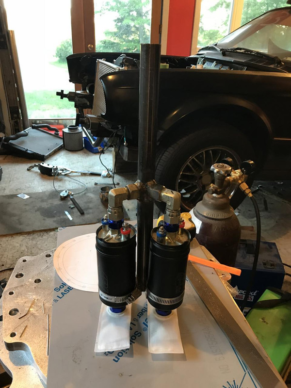
I decided to put the pump inside the fuel cell and add a sump. Here is the very crude and ugly hanger I made for the pumps. There are 3 elbows feeding into the center tube. I only have 2 pumps for now so the third is blocked off for future needs.
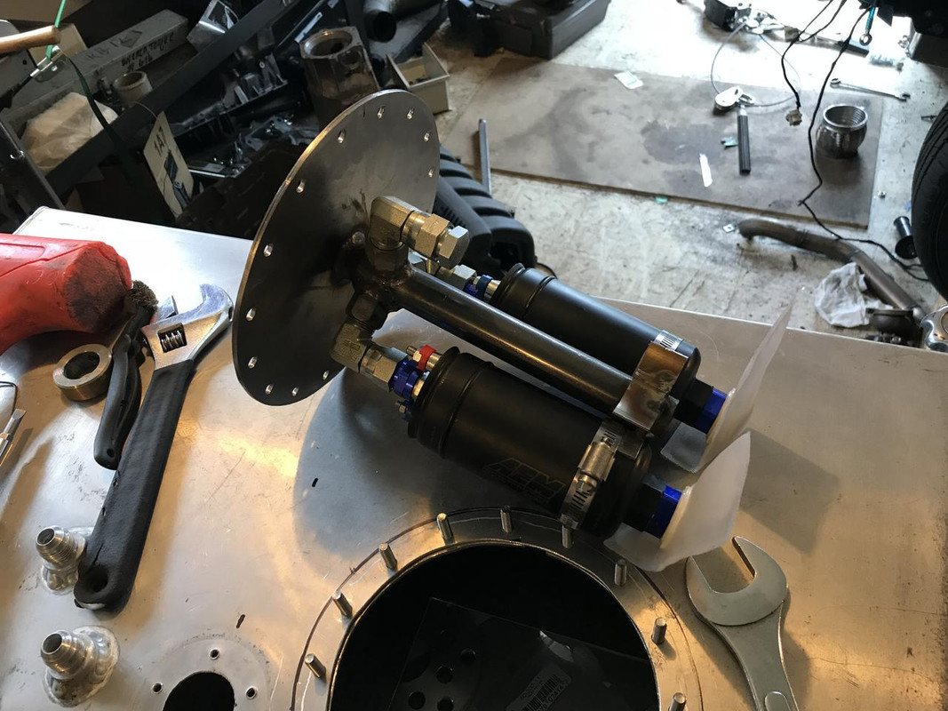
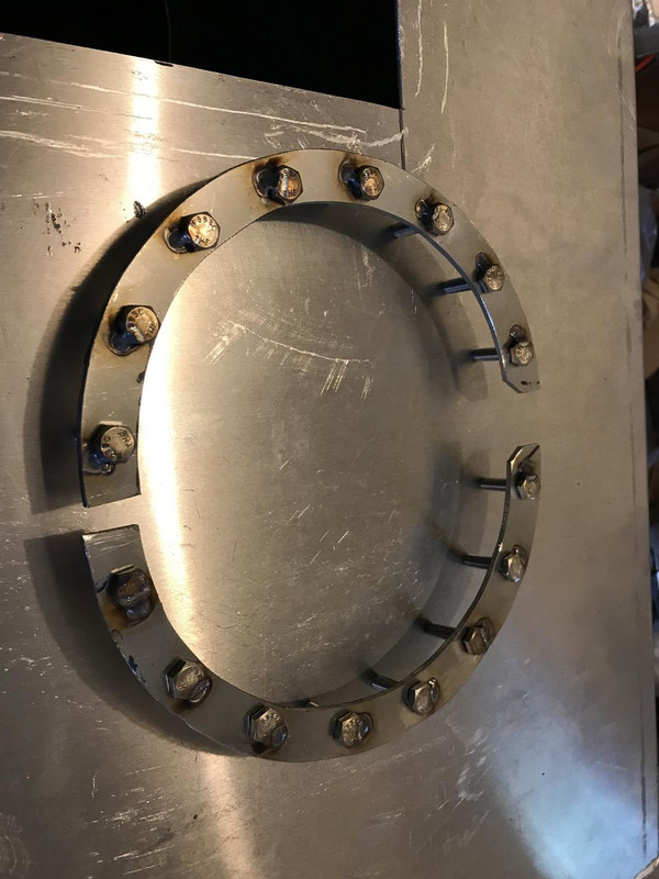
Stainless steel mounting flange on the hanger and new access port cut into the cell.
These two stainless horseshoes capture the bolts and reinforce the underside of the cell to help seal the gasket.
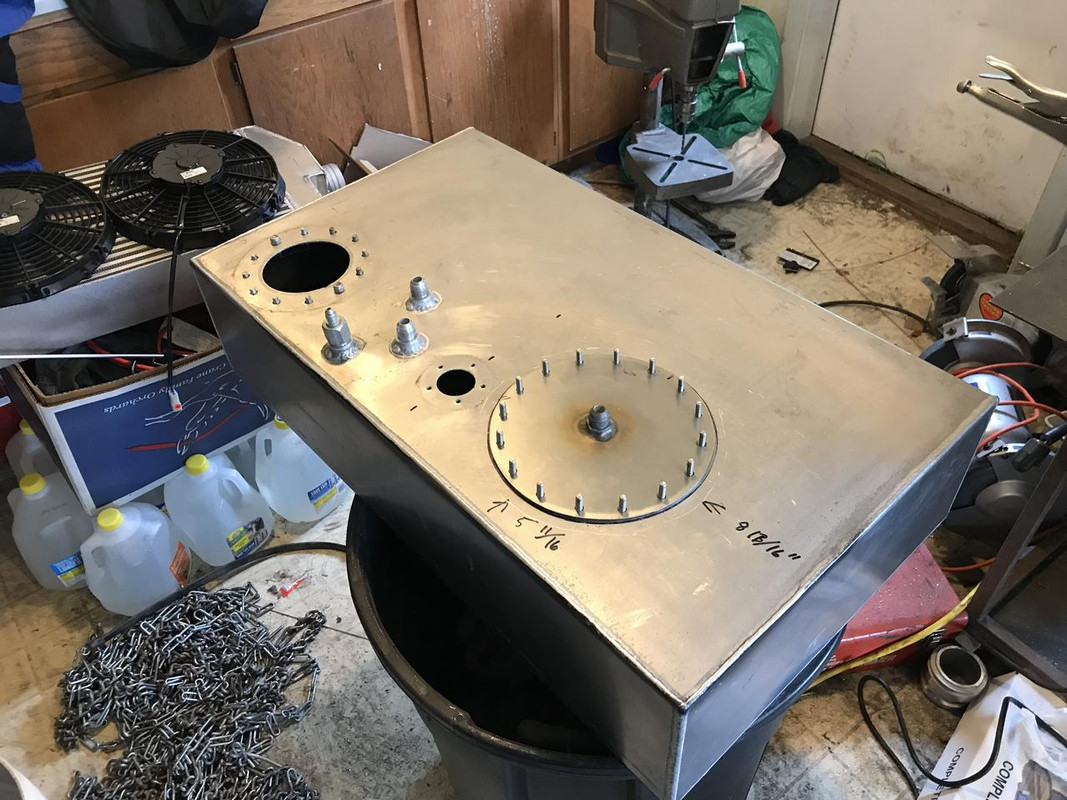
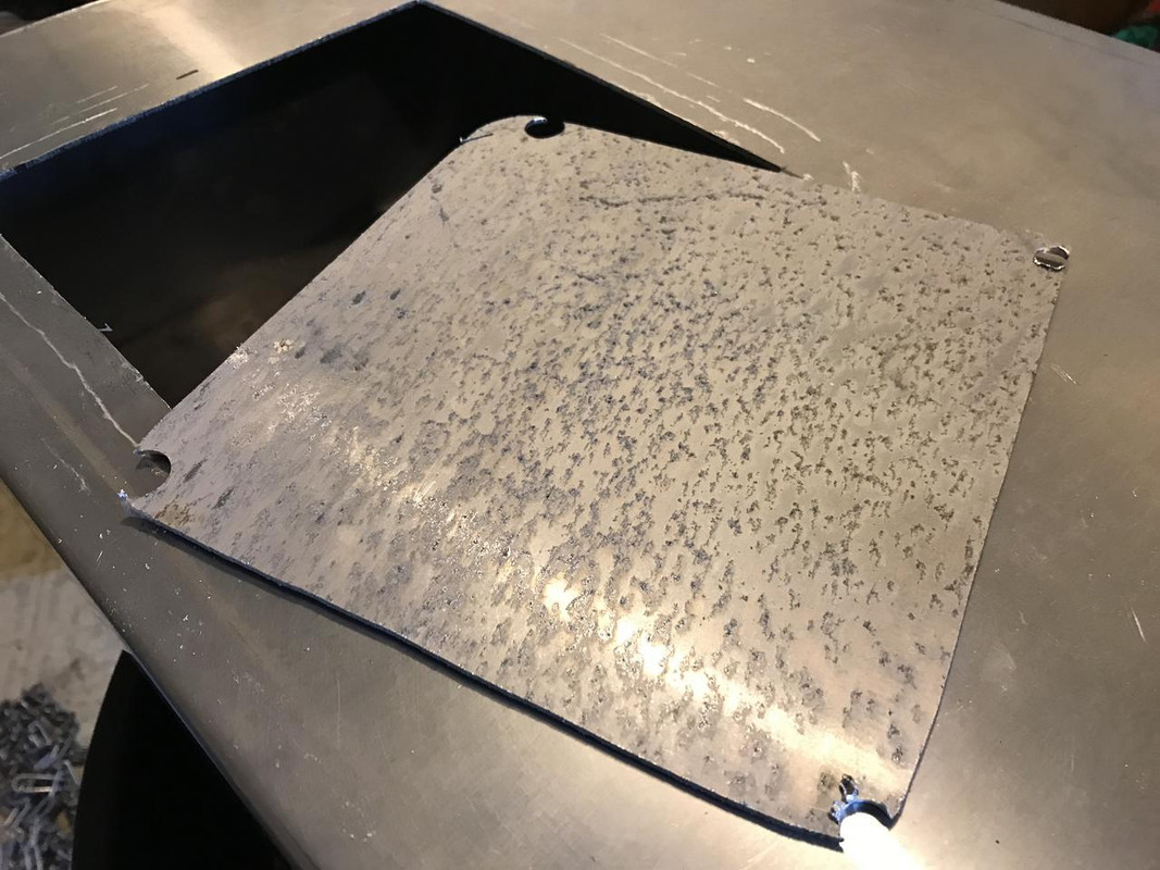
Cutting out for a sump. Corrosion from E85 sitting in the tank. Its not as bad as it looks, it comes right off with sandpaper.
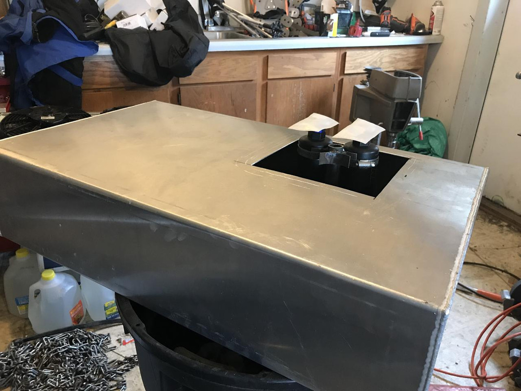
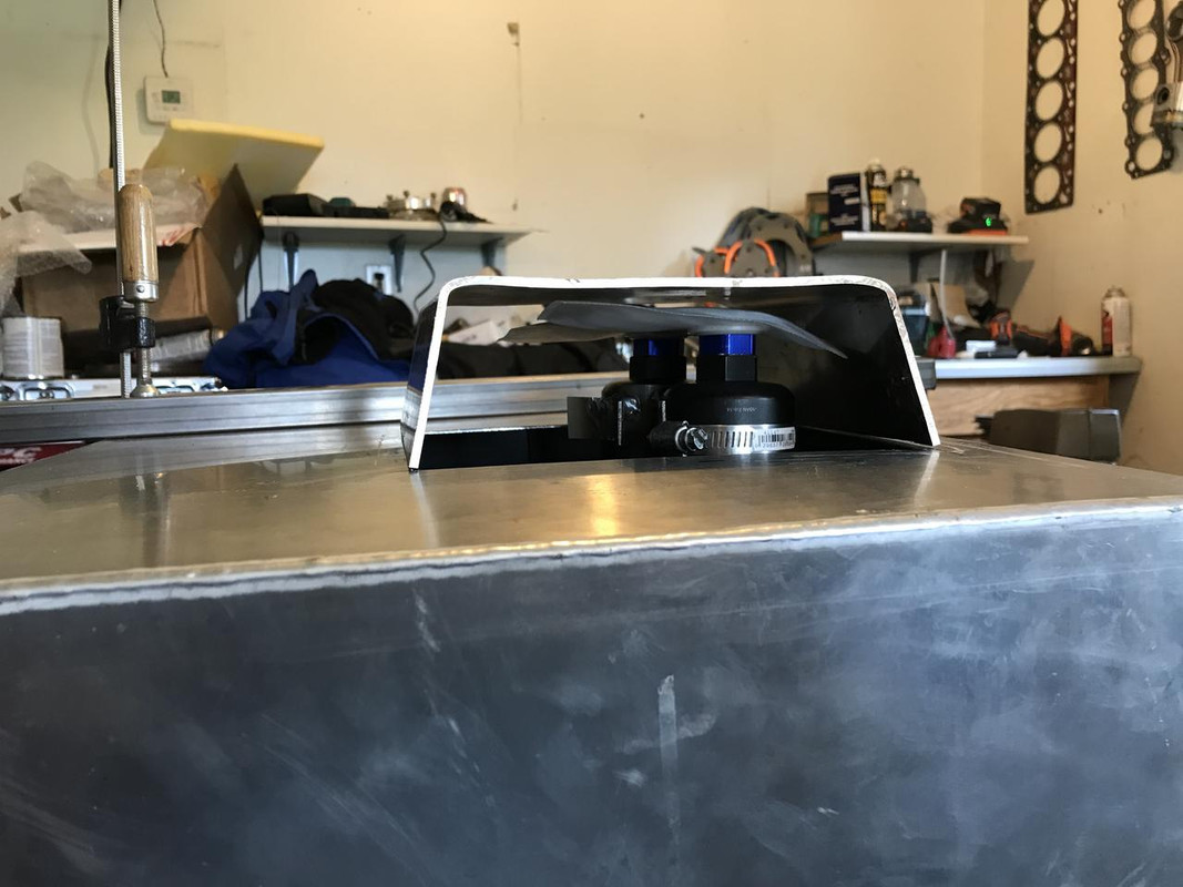
finished cell in place
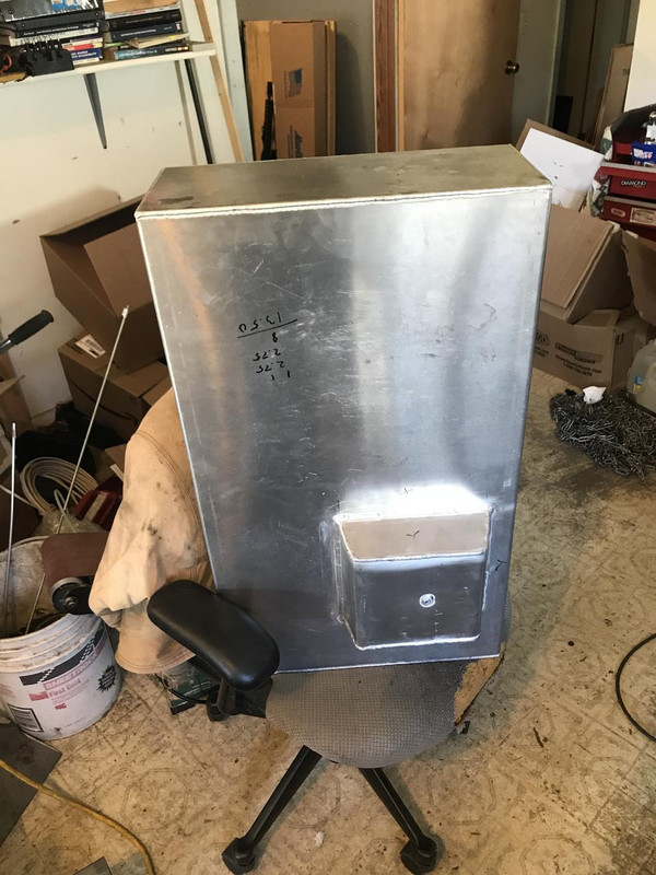
Also in the trunk is a 2.5 gallon water meth tank and pump. I made the mount bracket from 11 ga aluminum cut out on the table say and bent in the vice.
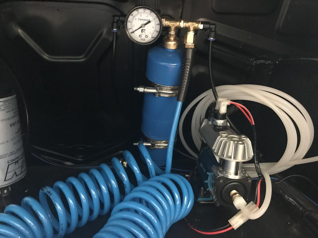
ARB air locker pump and air tank. The air tank is a 1lb torch cylinder with the valve taken out. The air is to feed the boost control system and I also added a flexy hose to air the rear tires up and down. The pump has a built in pressure switch that cycles on at 70 psi and off at 100 and its wired to power on with the ignition switch. The coiled up hose on the inlet is just to quiet the pump down.
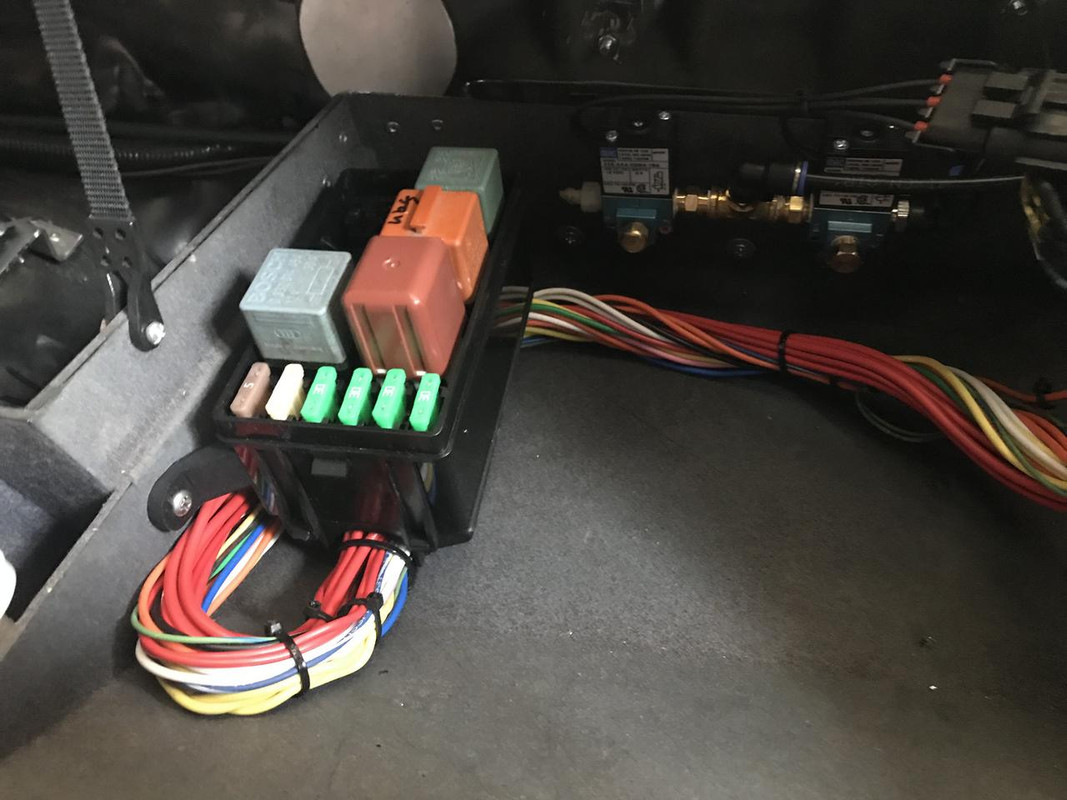
New fuse/relay box for the trunk. It has relays for 3 fuel pumps, the air pump and the water meth pump.
Up front here is the new wiring for the engine controls. Fuse/relay box in the glove box with relays for main power, coil, injectors, nitrous solenoids, fans, and the converter dump valve. The two air solenoids are for boost control. One fills the wastegate from the compressor and the other releases pressure to atmosphere with a restrictor to slow down the flow.
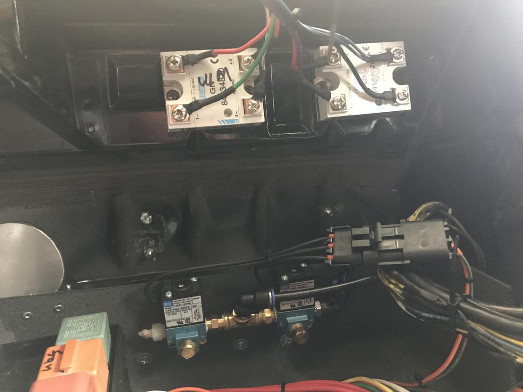
Two solid state relays on the firewall. One controls the transbrake and the other the water meth injector.
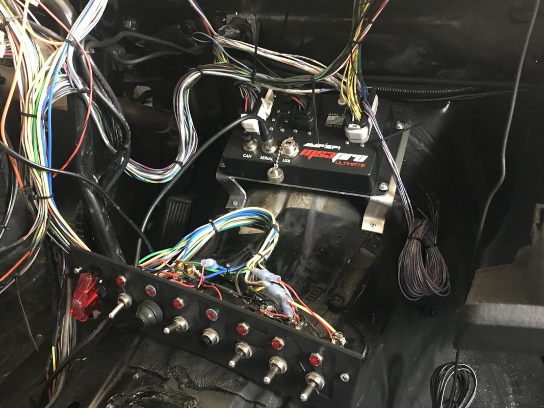
MS3 ultimate mounted on the trans tunnel. The switch panel is the same one as before. Still some tiddying to do with the wiring. I made everything in the car except the lights and power windows from scratch so the wiring was a little daunting. I used like 1500 feet of wire.
Switches are from left to right:
line lock
ignition
starter
nitrous arm
datalog
fuel pump one (up is computer control, middle is off, down is manual on)
fuel pump two (up is computer control, middle is off, down is manual on)
cooling fans (up is computer control, middle is off, down is manual on)
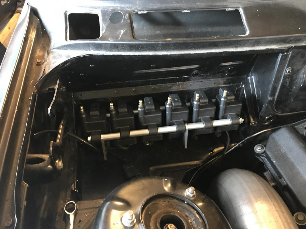
New coils on the passenger firewall. These are the IGN1 coils. They happen to be holley's. Bracket is from ICT billet. The wiring for the passenger side wheel speed sensor, dome pressure sensor and drive pressure sensor are running through the fender.
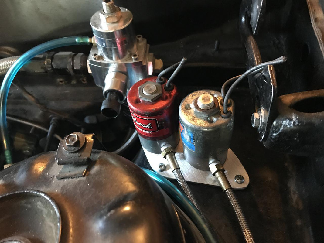
Nitrous solenoids on the drivers side.
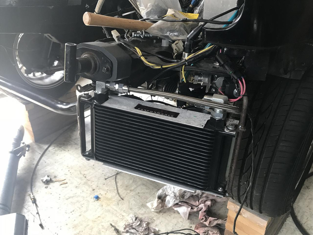
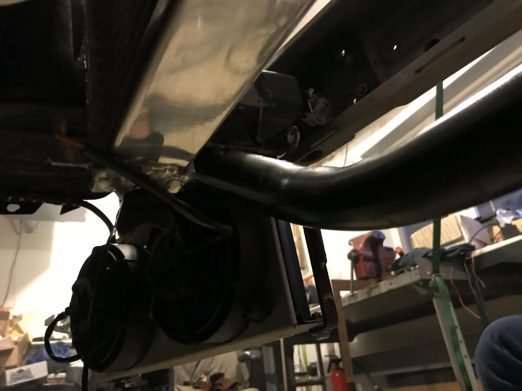
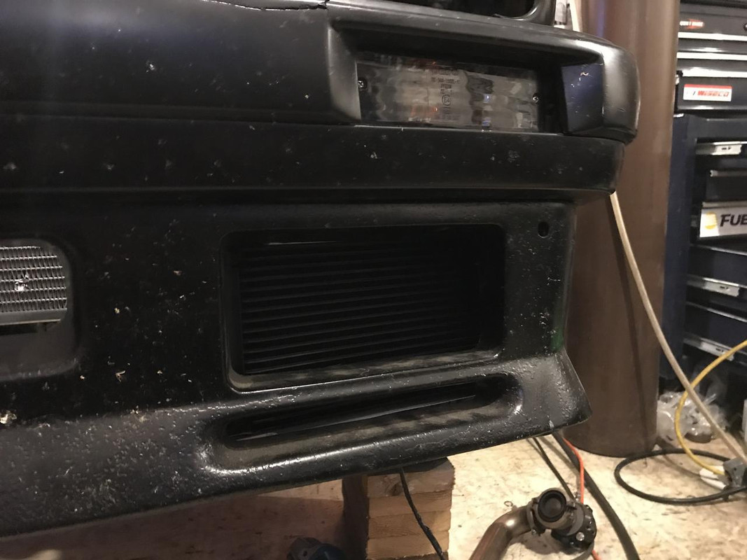
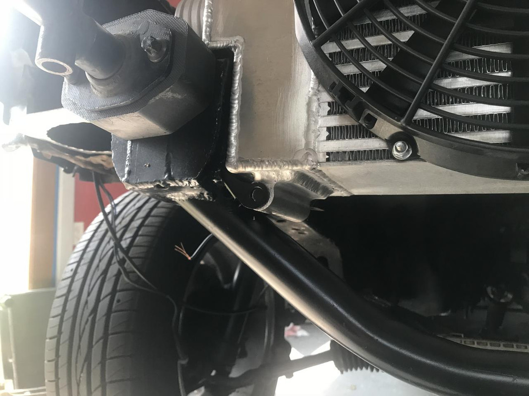
transmission cooler and fans on the front drivers side.
Sized to fill the fog light opening in the front bumper. The brackets are also made to bend out of the way in case I hit something
This solenoid behind the cooler is the converter dump valve. The fluid in a transmission goes from the pump through the torque converter, then to the cooler, and then to the lubrication circuit. This valve dumps the oil from the cooler back into the pan to lower the pressure in the converter and make it easier to spool on the transbrake. The ECU is wired to control it. It will turn on with the transbrake and shut off at a predetermined boost level.
Last edited by someguy2800; 08-20-2018 at 05:41 PM.
86 325es, 2.8L m50, S476sxe, ProEFI 128 ecu, e85, solid rear axle, TH400 trans, 28x10.5w slicks, zip ties, popsicle sticks, tape
best time 9.06 @ 151.8 mph, best 60 foot 1.30
u owe my mule an apology
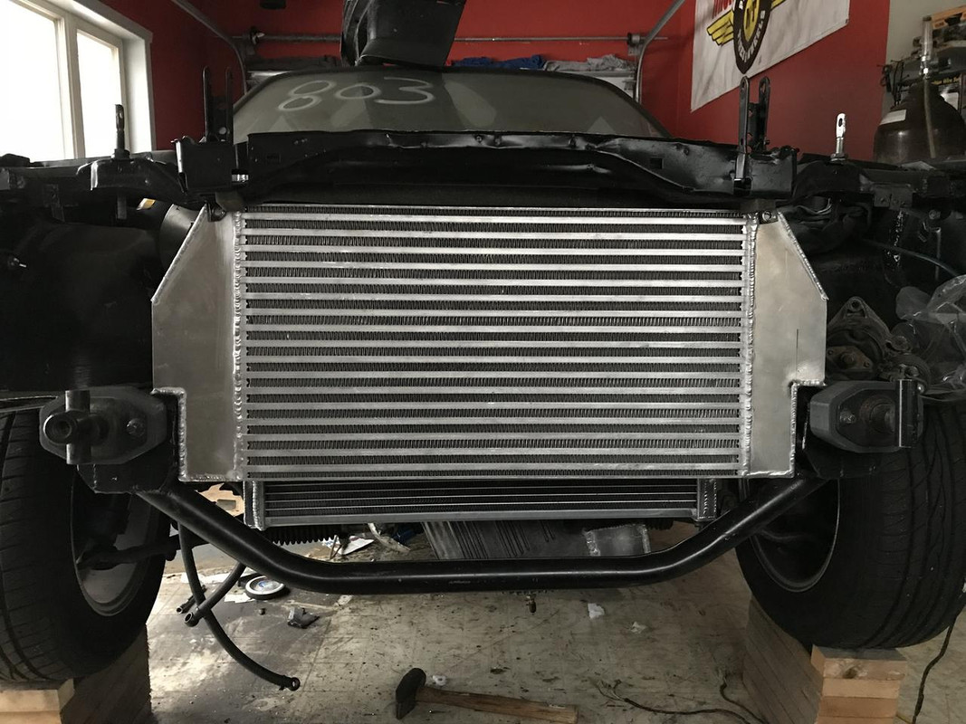
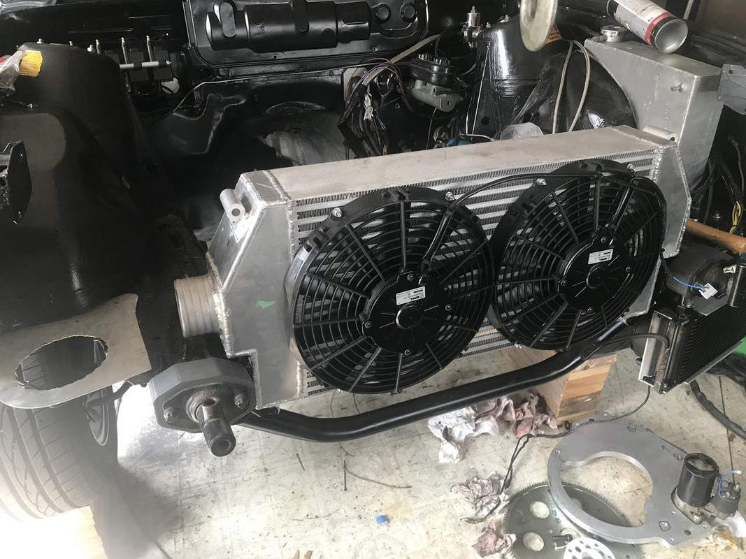
New intercooler. This was a vibrant bare core and I made the end tanks. I think the core is 22x12x4.5"
Two 11" spall fans mounted on the front
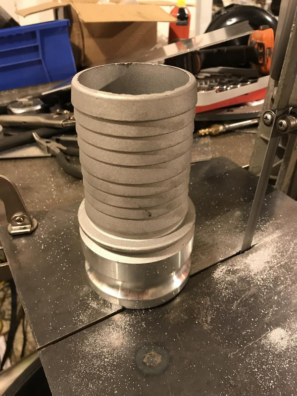
The hose barbs for the inlet and outlets are just a 3" fire hose fitting cut down.
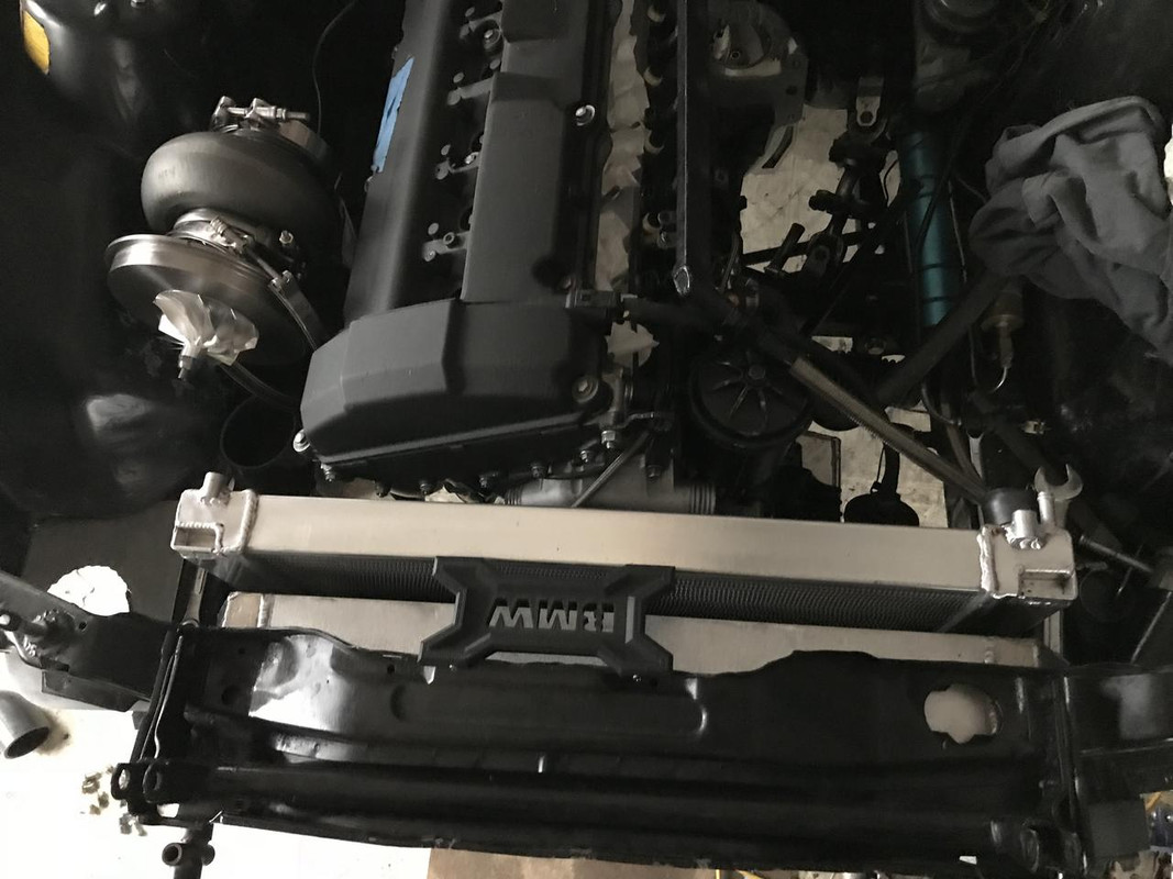
Mounting brackets on the frame. Just as with my last setup the upper radiator support will bolt to the top of the intercooler so the intercooler will act as the front core support
I had a fixture to make repeatable pie cuts on my cold saw.
Always wanted to try building tubes with pie cuts. I like it.
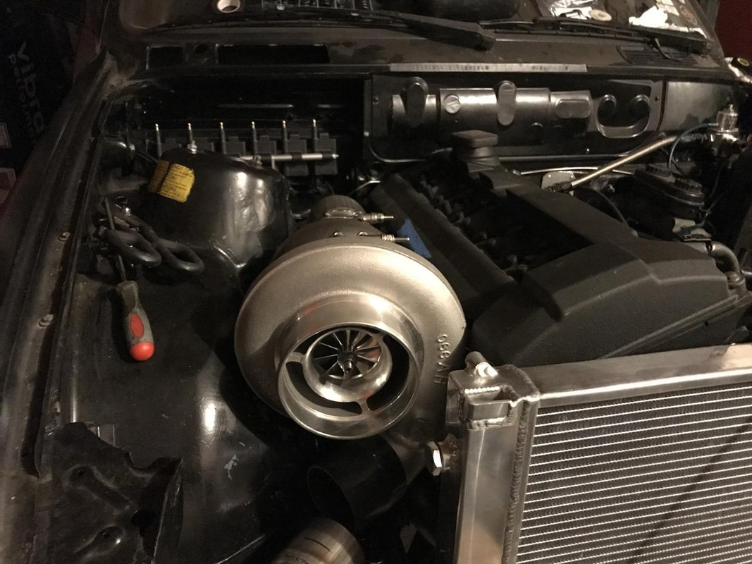
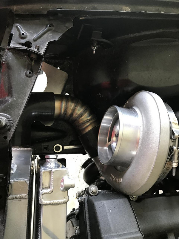
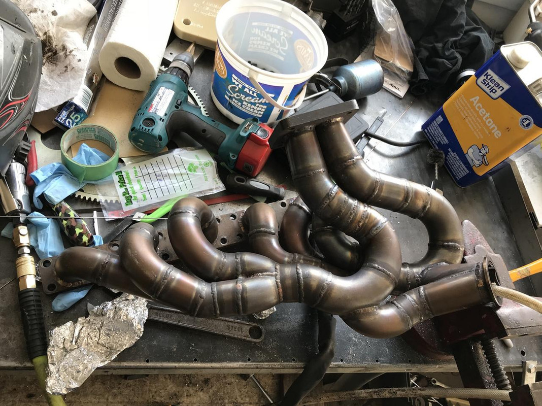
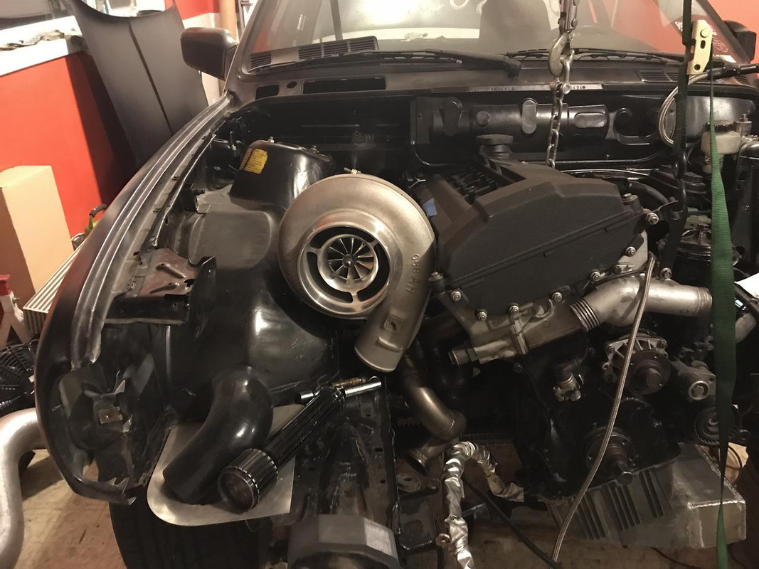
A little out of order but I had to cut up my manifold to fit the new turbo. It just wouldn't clear the valve cover otherwise. I moved the mounting flange back about and inch and turned it slightly toward the passenger side. I was just using scraps from the original so there is a totally unnecessary number of pieces in there. Its not quite equal length anymore but I don't give a shit.
I did have to dent the fender just a tiny bit to fit, like 1/2".
It clears the hood by like a full inch.
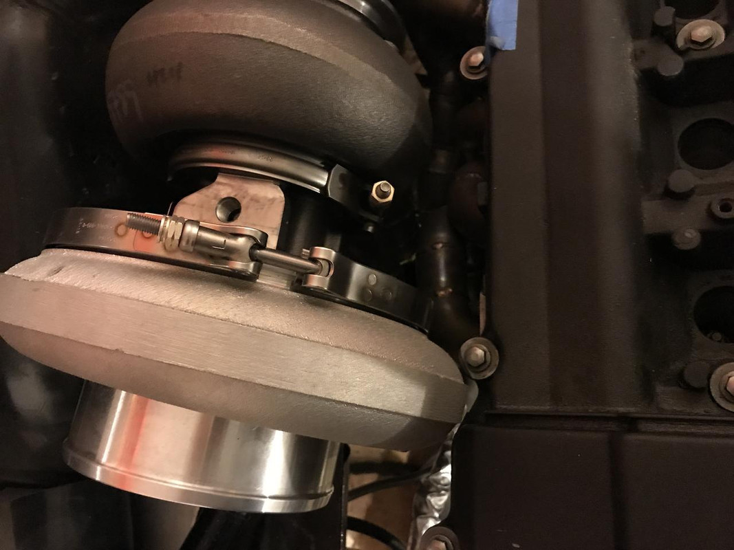
90 degree elbow on the outlet
Last edited by someguy2800; 08-18-2018 at 04:02 PM.
86 325es, 2.8L m50, S476sxe, ProEFI 128 ecu, e85, solid rear axle, TH400 trans, 28x10.5w slicks, zip ties, popsicle sticks, tape
best time 9.06 @ 151.8 mph, best 60 foot 1.30
u owe my mule an apology
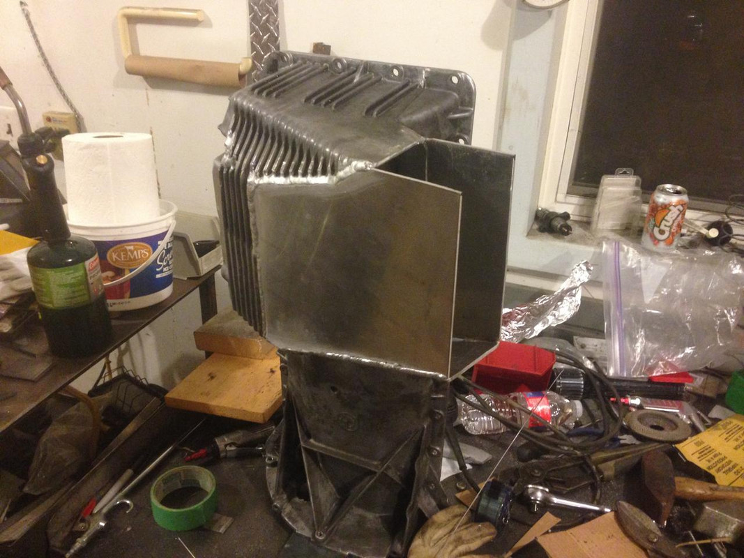
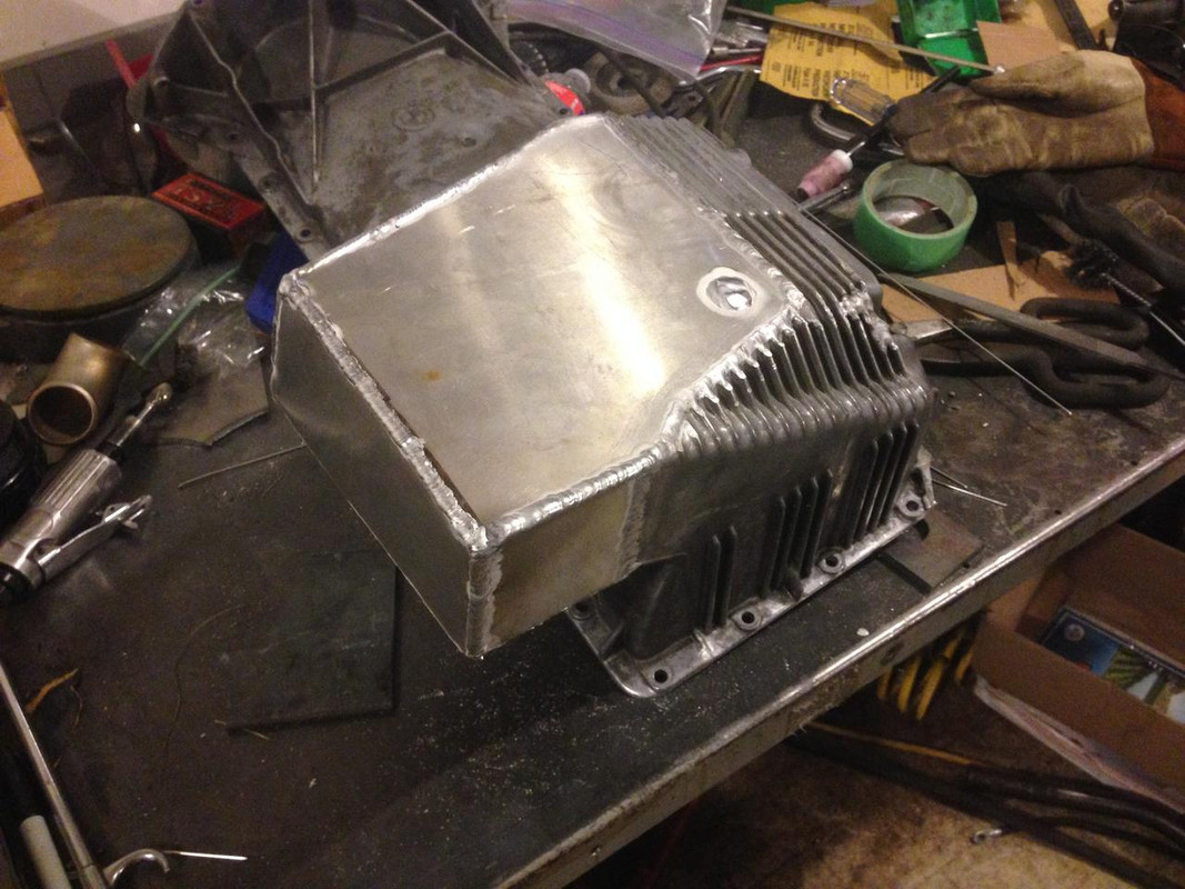
Fixing the smashed oil pan and adding some capacity and baffles
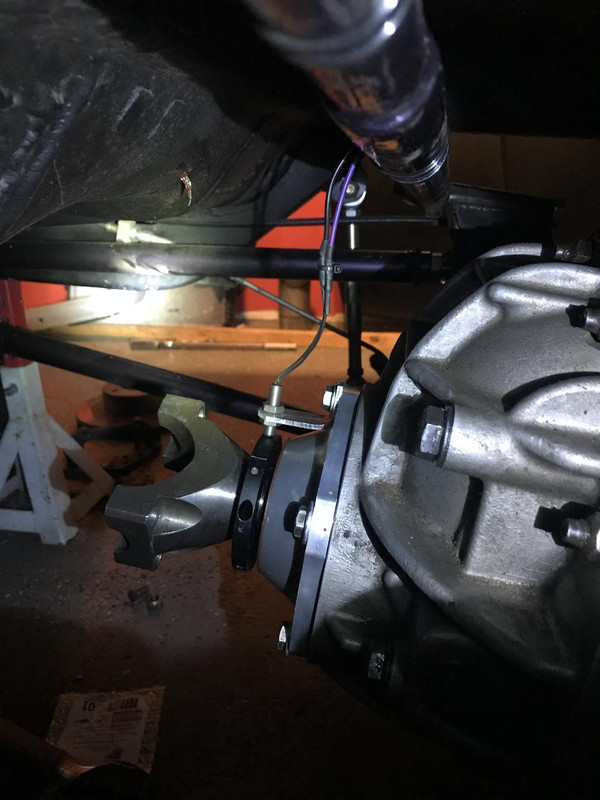
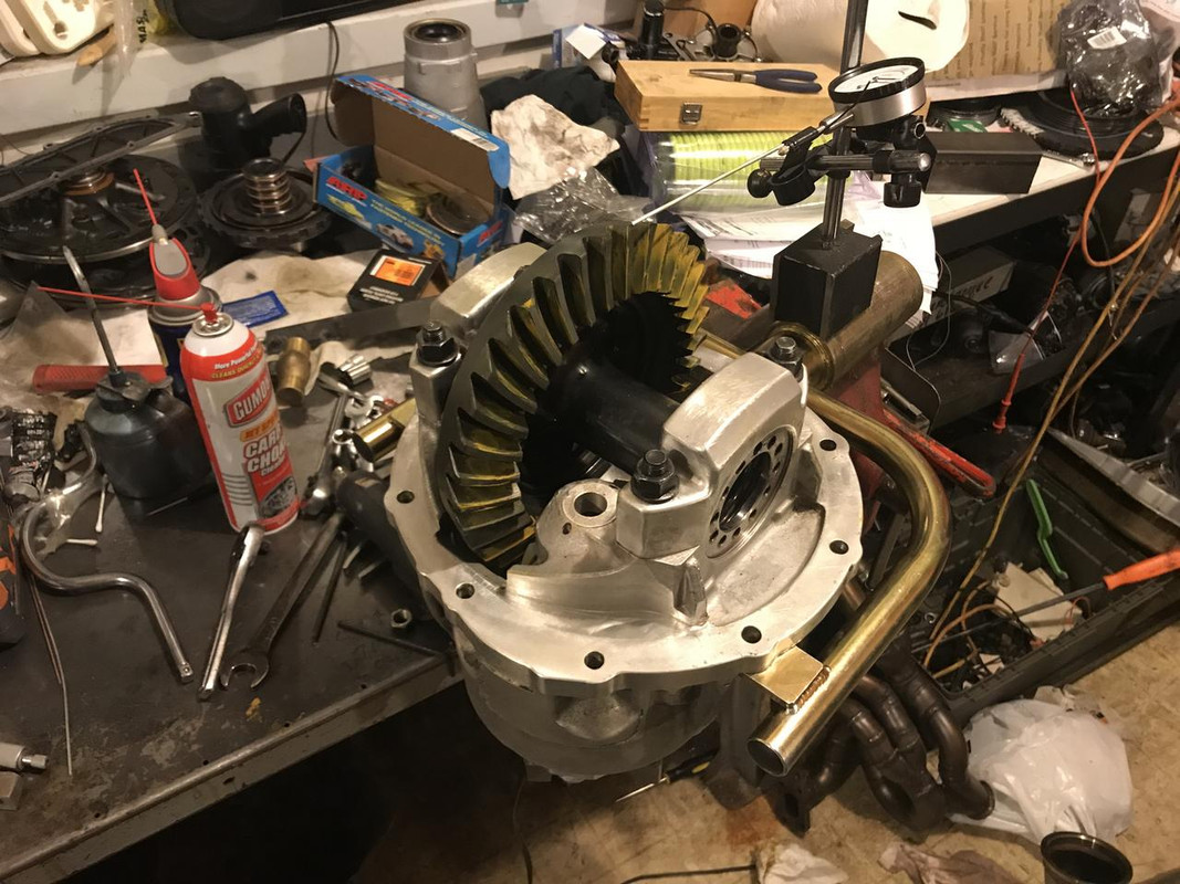
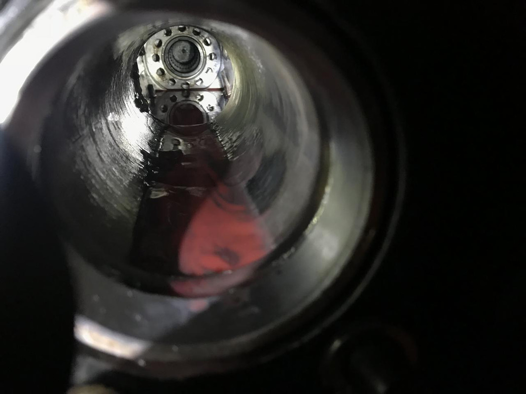
Rear gear needed to be changed for the auto trans. I took out the old 4.22 ratio and put a new 3.50 in. Axles looked great, no twisting in the splines.
Figured out I could refill the rear end full of oil by jacking up one side and pouring it in through the axle tube. The only gear lube I use is redline shockproof. It is like 75w250 and the using it the gears stay like new forever. I don't usually buy into magic lubricants but the stuff really works.
I also added a tone wheel on the pinion yoke to capture rear wheel speed. The ring has 8 magnets in alternating polarities. The sensor is a 2 wire reed switch from reed switch development corp. They were very helpful in talking me through to get the right sensor.
Last edited by someguy2800; 08-18-2018 at 04:17 PM.
86 325es, 2.8L m50, S476sxe, ProEFI 128 ecu, e85, solid rear axle, TH400 trans, 28x10.5w slicks, zip ties, popsicle sticks, tape
best time 9.06 @ 151.8 mph, best 60 foot 1.30
u owe my mule an apology
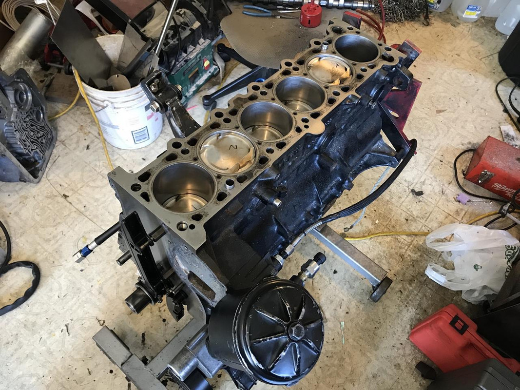
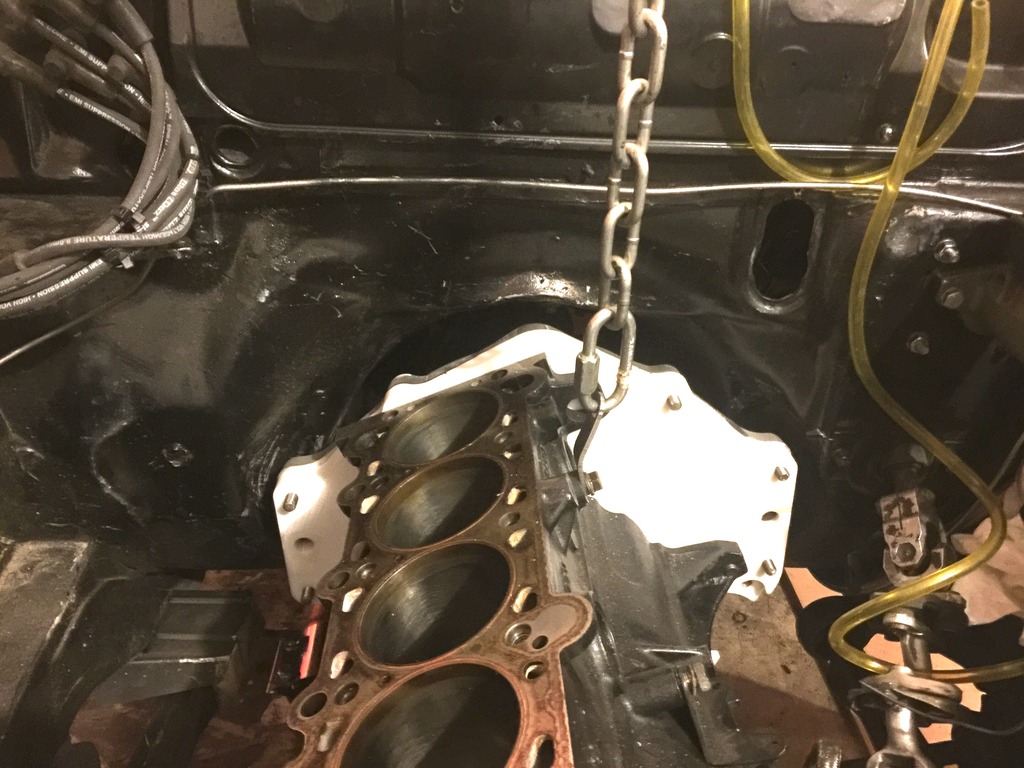
Motor is back together. You can follow the damage I found after wringing its neck out while it was lean. Long story short is bent rods and nearly blown headgasket.
https://www.bimmerforums.com/forum/s...ock-headgasket
I actually didn't know anything was wrong with it, the plan was just to put new rods, main bearings, and a cutring gasket in it.
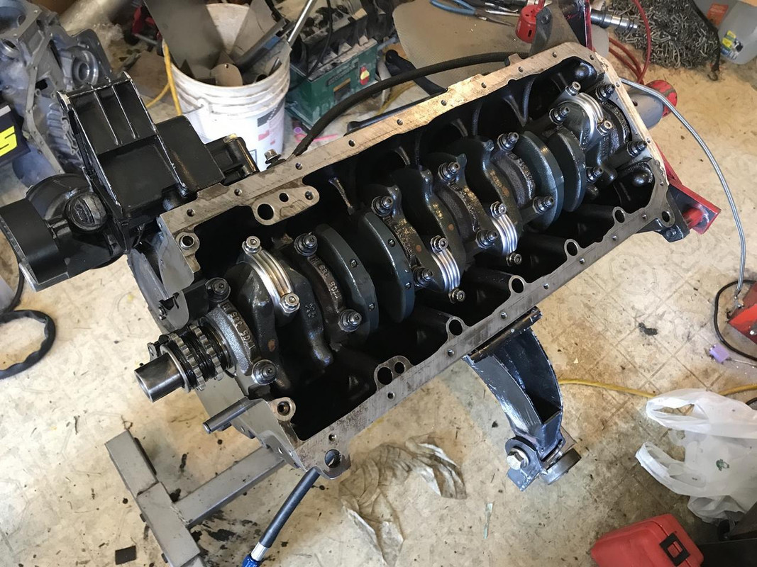
I put ACL main bearings in it. There was nothing wrong with the old oem ones, I just wanted something with a little more clearance. The stock ones were around .0012" clearance, I set the ACL's to .0028"
Eagle rods with the old wiseco pistons in. ARP main studs as well.
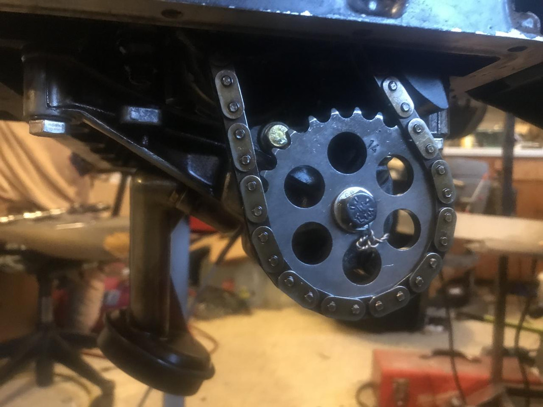
Oil pump re safety wired with the achilles oil pump shaft.
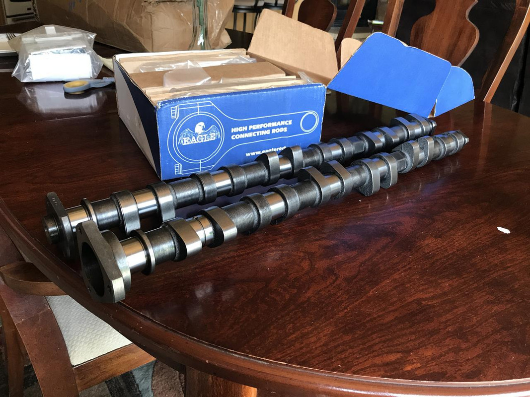
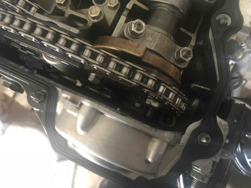
I bought a set of vac turbo cams for a steal on ebay. They are the aggressive grind for hydraulic lifters. The specs they list on the website are wrong, or at least that is not what I got. I called them on the phone and asked them what these were supposed to be from the part numbers and they said they are supposed to be 280/264 cams with a 116/116 LSA.
https://store.vacmotorsports.com/bmw...rts-p1433.aspx
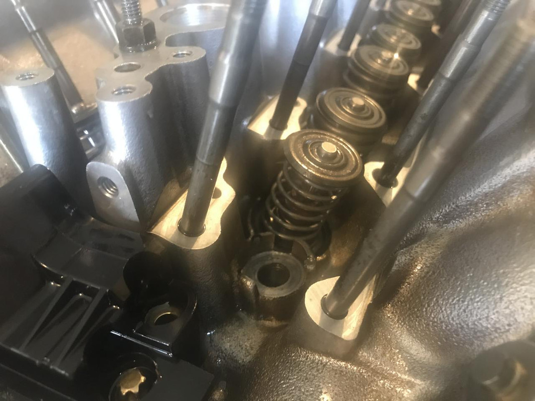
To check the valve clearance I pulled the front exhaust and intake valve spring from the head and put it on the block with a set of check springs installed.
With a degree wheel on the motor I set it to 0, 5, 10 and 15 deg btdc and then measured the amount of valve travel to hit the piston. This way I have the clearance mapped out and can calculate the clearance for any given lift profile
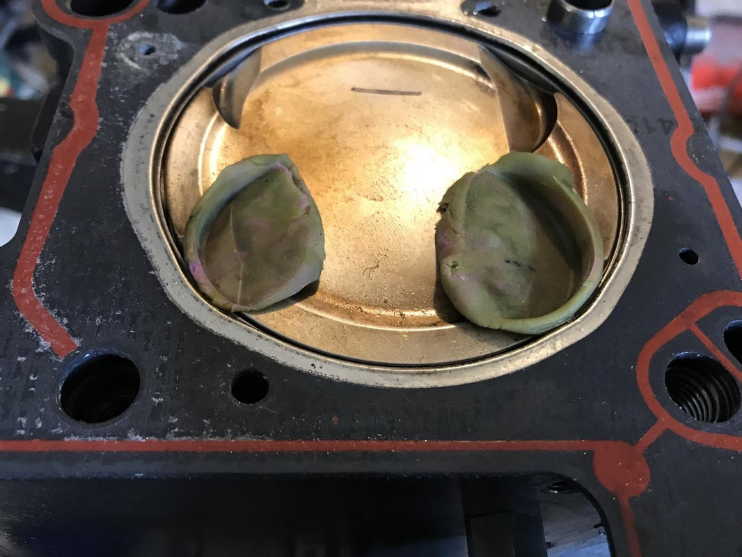
I did also do a quick playdough check at TDC just to make sure the valves had radial clearance.
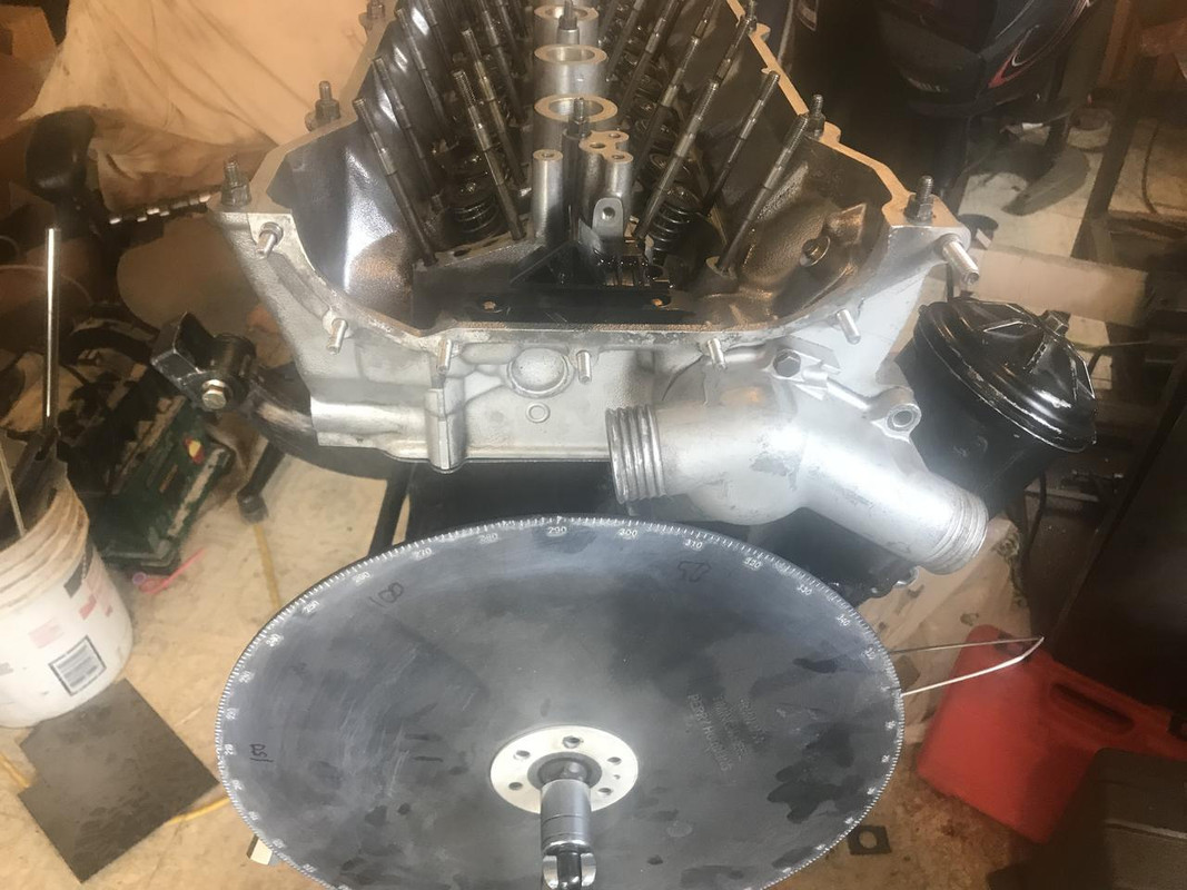
Put the cams in and measured the lifter travel vs crank rotation to get the lift profiles and timing of both.
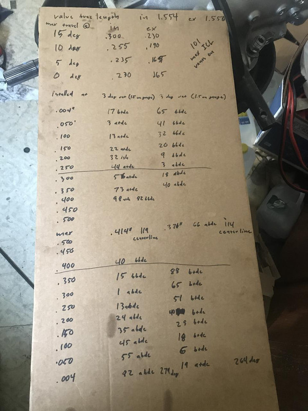
Here is the raw data. Note that both cams were 3 degrees retarded as that just how they ended up after installing them with the blocks and then rotating the motor a couple times. The numbers vac gave me were correct. They are 280/264, 116 lsa and 10.5/9.4 lift.
My intention was to install them at 116 intake and 118 exhaust and use vanos, but after doing the math I found that the intake valves would not have sufficient clearance with the vanos active. The intake valves would only have like .030" clearance which is not enough, so the vanos will need to be limited. I calculated that in order to maintain valve clearance the lobe center of the intake cam must be no less than 100 degrees, so with a 116 degree lobe center the vanos can only travel 16 degrees of crank rotation instead of the stock 25. The vanos unit has 10mm of travel so I guess I will need a 4mm travel shim inside. I took my vanos unit apart last night to start making a shim but I broke the bolt off inside.
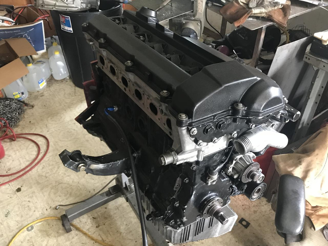
So for now I set the cams to 110 on the intake, 118 exhaust and locked the vanos travel. I also put the gutted vanos cover on and will just plug the solenoid until I get parts to fix the vanos.
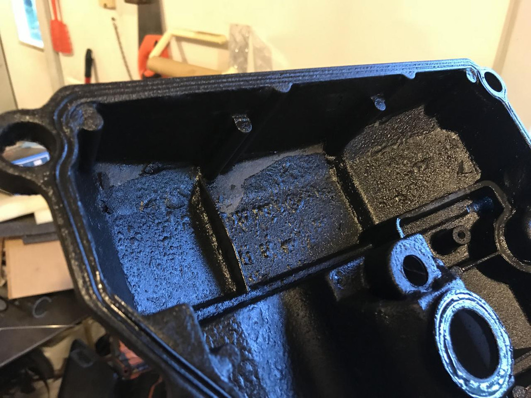
The reason I did this instead of putting the non vanos cover back on is because when pulling the motor apart I found the powdercoat was peeling off the inside of my non vanos cover in big bubbles and flakes.
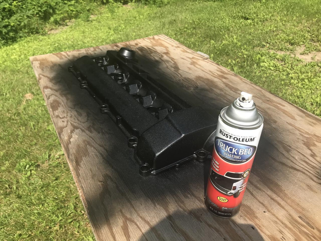
Since I had planned on putting the vanos back on I also stripped, shaved, and coated a new vanos cover last weekend already.
Motor back together
Its been a hectic couple weeks. I started assembling the trans a couple weeks ago so I set the trans up on the engine stand and layed out all the parts on the bench. Then I found the new low roller clutch for the trans was bent so I put the trans stuff away and decided to rebuild the motor while I waited for that. Then I found the motor was all messed up so I had to wait for parts for that. Then I decided to change the rear gear while I waited for engine parts but then found the new ring and pinion was junk and had to order a different set. Well rear end done, engine done, now time to get back to the trans.
Last edited by someguy2800; 08-18-2018 at 08:05 PM.
86 325es, 2.8L m50, S476sxe, ProEFI 128 ecu, e85, solid rear axle, TH400 trans, 28x10.5w slicks, zip ties, popsicle sticks, tape
best time 9.06 @ 151.8 mph, best 60 foot 1.30
Member
Stellar update sir!
95 turbo 330ti. 01 maxpsi m3 e85. 01 m5. 01 m coupe. 03 AIM 996t e85. 06 x3 w/Meyers plow and winter daily. Prussian Motors is hiring!! prussianmotors.com/jobs
Current e39t LS Turbo swap: https://www.bimmerforums.com/forum/s...LS-e39-Touring
Member
Nice update! This thing is sick.
PTE6262 .63 A/R, Stock S52, Cutring/Copper Spacer/Arp Studs Combo, Water Methanol Injected
10.9@131mph. #AngerMotorsports
Member
Wow, you've been busy!! And here I thought you were just out in the woods blowing shit up and testing out ammo.
After just going through my TH400 twice, you'd think I could envision the low roller clutch, but nope... Lol
u owe my mule an apology
Well there has been quite a lot of shooting going on here, that’s the reason I didn’t do anything on the car last year. I spent the entire year buying guns and shooting stuff. It was great.
86 325es, 2.8L m50, S476sxe, ProEFI 128 ecu, e85, solid rear axle, TH400 trans, 28x10.5w slicks, zip ties, popsicle sticks, tape
best time 9.06 @ 151.8 mph, best 60 foot 1.30
Member
Can I move up there and have you train me like some kind of ancient Shaolin kung fu master? I'll bring my own dogsled team, some good ole Tennessee whiskey, and a whole lot of that chronic.
Member
Low roller clutch is the one on the direct drum I probably refer to as a "sprag," huh? I went with a 4L80e one on an actual 4L80e direct drum. I may spring for a fancy billet aluminum one from CK later though...
u owe my mule an apology
Low roller is the one that fits inside the first planetary drum, right under the center support. The one on the direct drum is the intermediate sprag. I have an ATI aluminum direct drum with a pro mod sprag. If your going to get an aluminum direct drum make sure you get one with a steel sleeve in the seal bore or it will eat itself to death on the street.
86 325es, 2.8L m50, S476sxe, ProEFI 128 ecu, e85, solid rear axle, TH400 trans, 28x10.5w slicks, zip ties, popsicle sticks, tape
best time 9.06 @ 151.8 mph, best 60 foot 1.30
Member
Light Fires N Burn Tires
Awesome update!
Why are you filling the rear end full of oil? I thought rear ends needed only be about 1/2 full or else they overheat?
u owe my mule an apology
I think you misunderstood. Its filled up to the bottom of the the axle tubes which is like 1/3 full.
86 325es, 2.8L m50, S476sxe, ProEFI 128 ecu, e85, solid rear axle, TH400 trans, 28x10.5w slicks, zip ties, popsicle sticks, tape
best time 9.06 @ 151.8 mph, best 60 foot 1.30
u owe my mule an apology
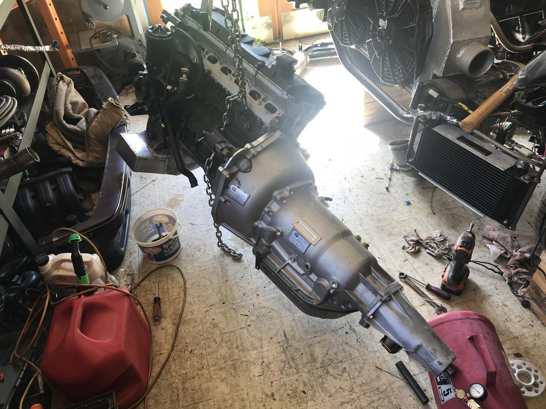
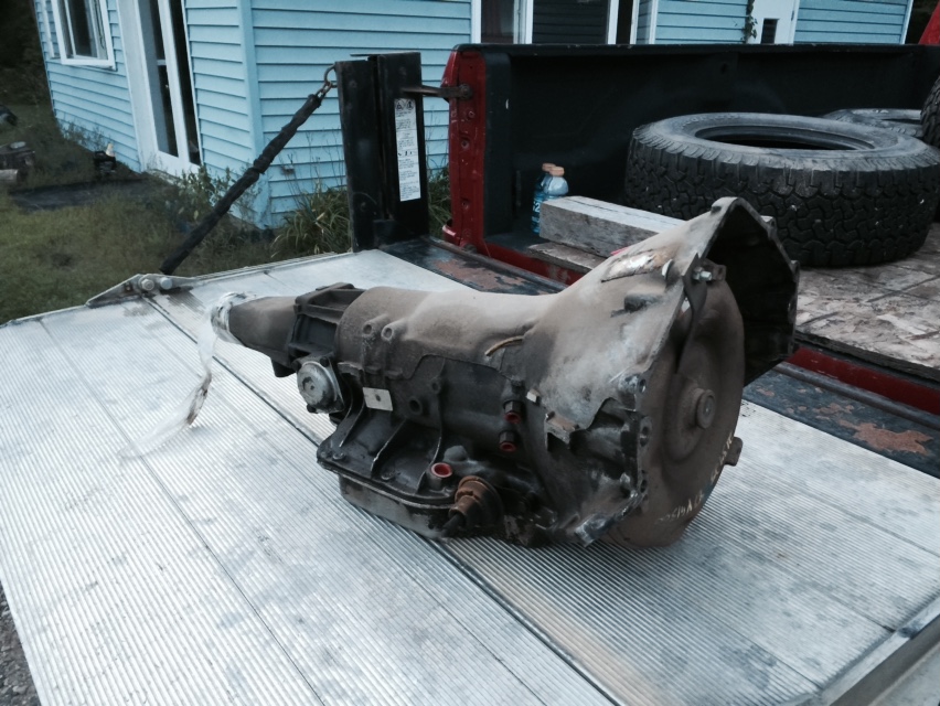
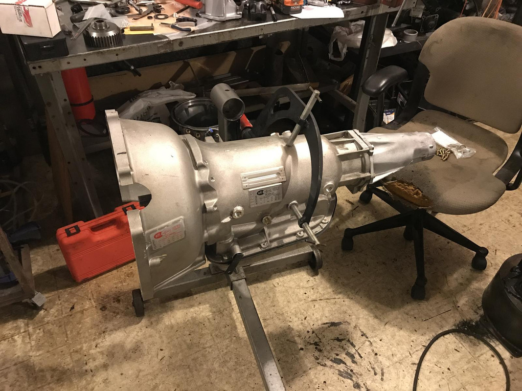
I finally got the transmission done and on the motor. Lots of family stuff going on and hard to find any time. If your not aware the transmission I am going to is a 3 speed chevy TH400. This was in heavy cars and trucks from 1964 to the early 90's. They are very common in 3/4 ton pickups, motorhomes, delivery vans, ect... The donor car for this trans was a 1987 chevy G20 van.
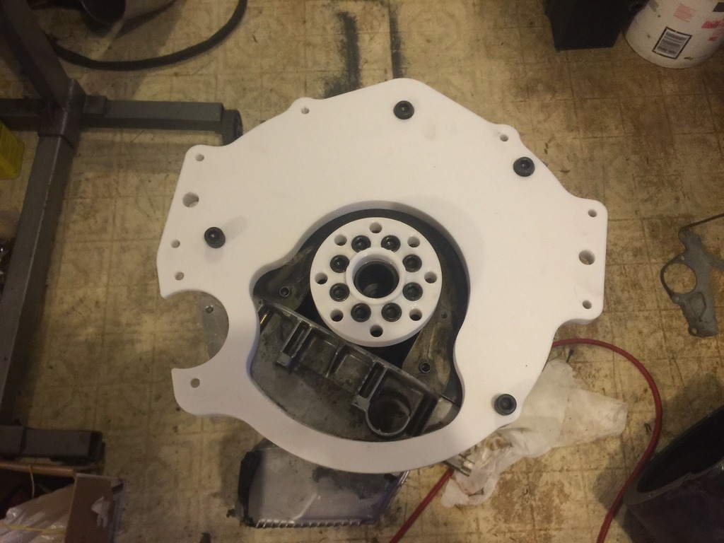
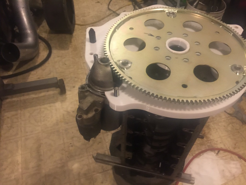
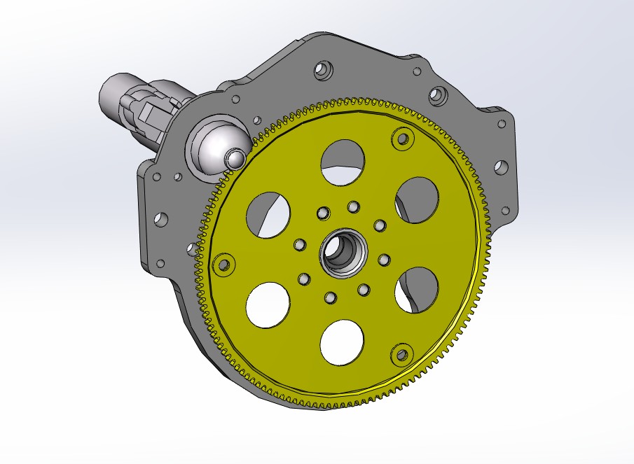
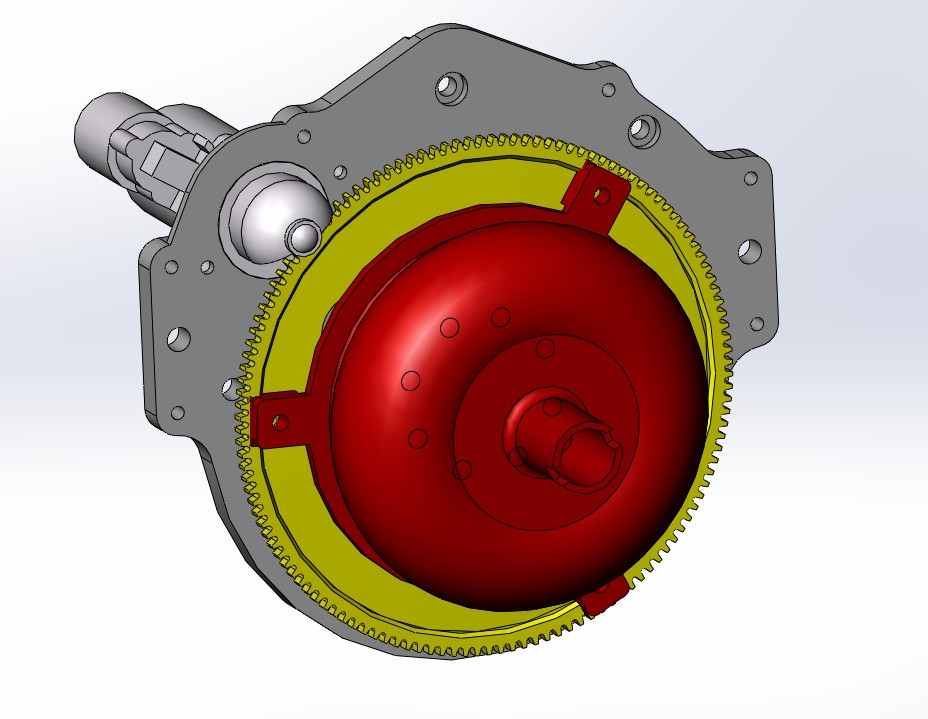
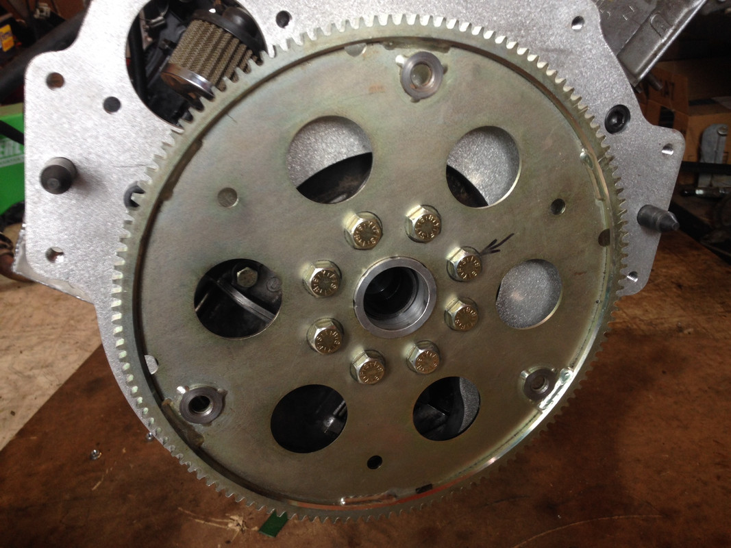
To adapt it to the BMW motor I designed an adapter plate for the bellhousing and an adapter for a V8 flexplate. After many hours of research I found the best flexplate to adapt to which is a chrysler hemi flexplate. This works best because the hemi uses 8 flywheel bolts instead of all the other american v8's which use 6, so it does not interfere with the bmw flywheel bolt pattern. They also make inexpensive hemi flexplates that already have a GM converter bolt pattern. The ring gear tooth profile is also identical to an M50 ring gear.
first prototype 3d printed out of polycarbonate
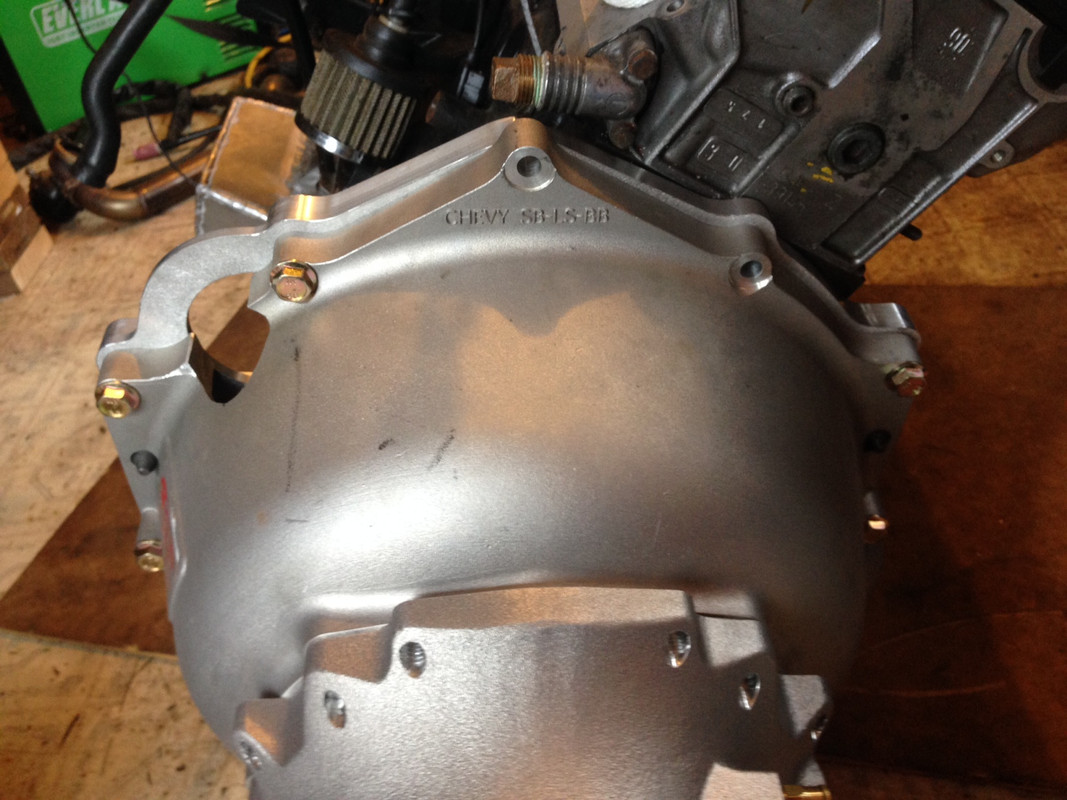
the starter on this version hit the crossmember so I redesigned to move it in the conventional location.
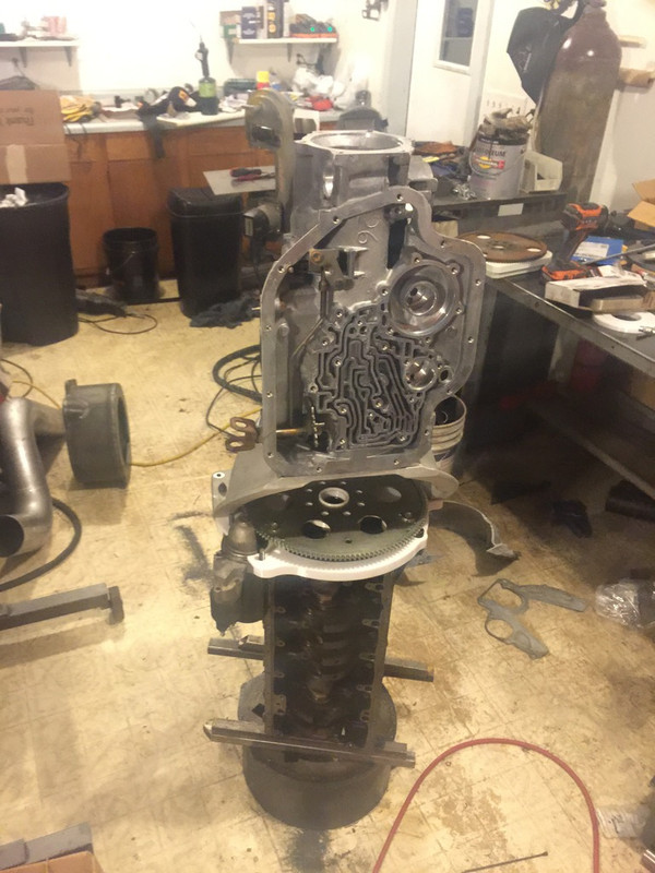
test fitting trans in car
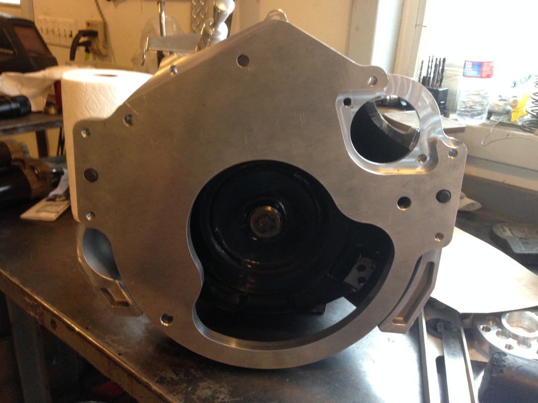
revised design
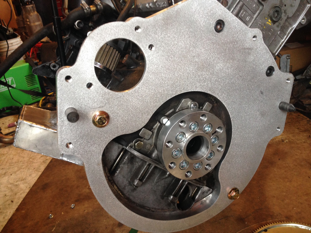
Final CNC aluminum adapter
Testing the starter
On to the actual trans build. I did not take many pictures since most of this is of little interest to this forum, but here is the breakdown of the transmission. It is built in an aftermarket case. The aftermarket case is not needed for these hp levels, the stock case works fine at 2000+ hp, but NHRA rules require either a transmission blanket or an SFI certified trans case at faster than 9.99. I tried last year test fitting the stock case with a blanket in the E30 tunnel and although it did fit, it was extremely tight and hard to work with so I sprung for the ATI case.
ATI sfi certified supercase.
ATI vasco input shaft and iron forward drum
TCS billet 4140 forward clutch hub
ATI vasco intermediate shaft
ATI billet alluminum direct drum with pro mod sprag and billet apply piston
ATI center support with oversize billet apply piston and bronze bushing on sealing race
borg warner low roller clutch
borg warner HD rear band
Sonnax reaction carrier shim kit
stock rear planets and gear set
stock 32 spline output shaft and tailhousing
roller thrust and output shaft bearings
CK performance transbrake valve body
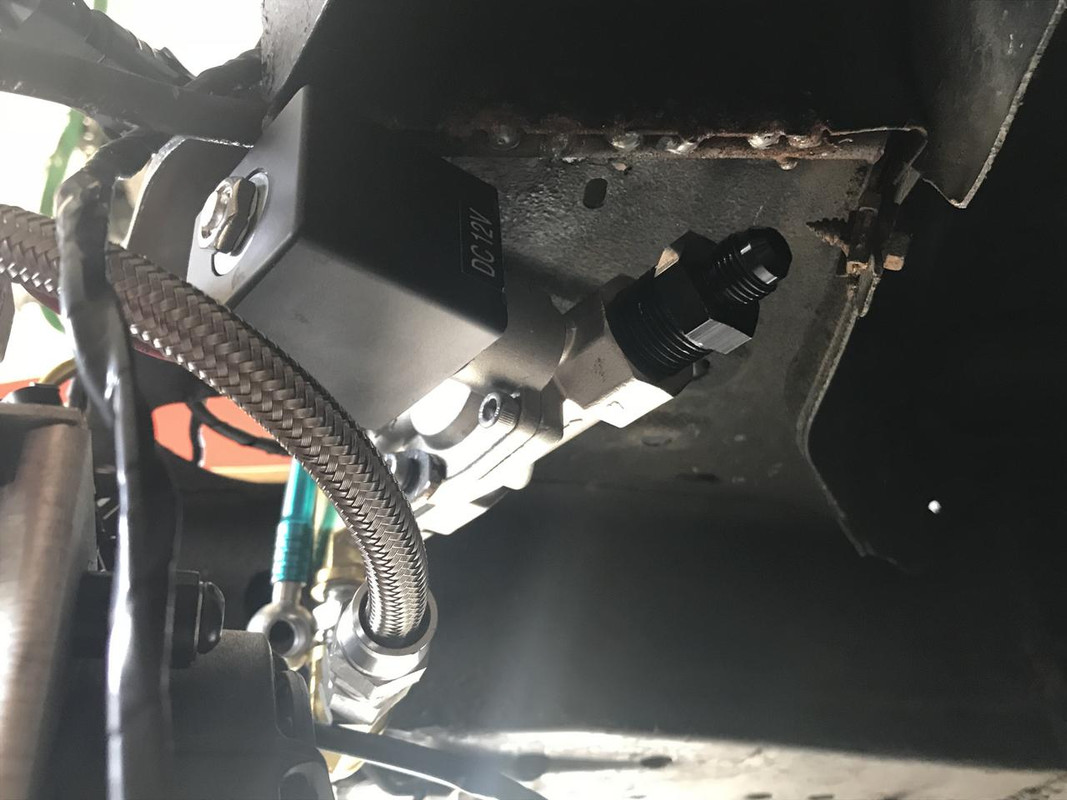
rebuilt pump with conveter feed restriction and CK fixed line pressure regulator
ATI hi flow filter
new bushings and seals
HD snap rings
6 smooth tan borg warner clutch's in forward drum
6 waffle borg warner hi energy frictions
4 borg warner smooth frictions
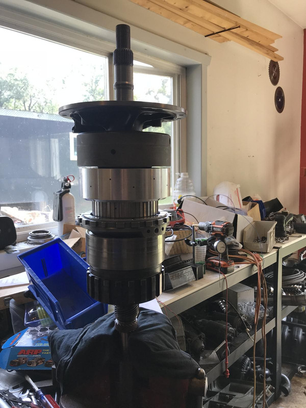
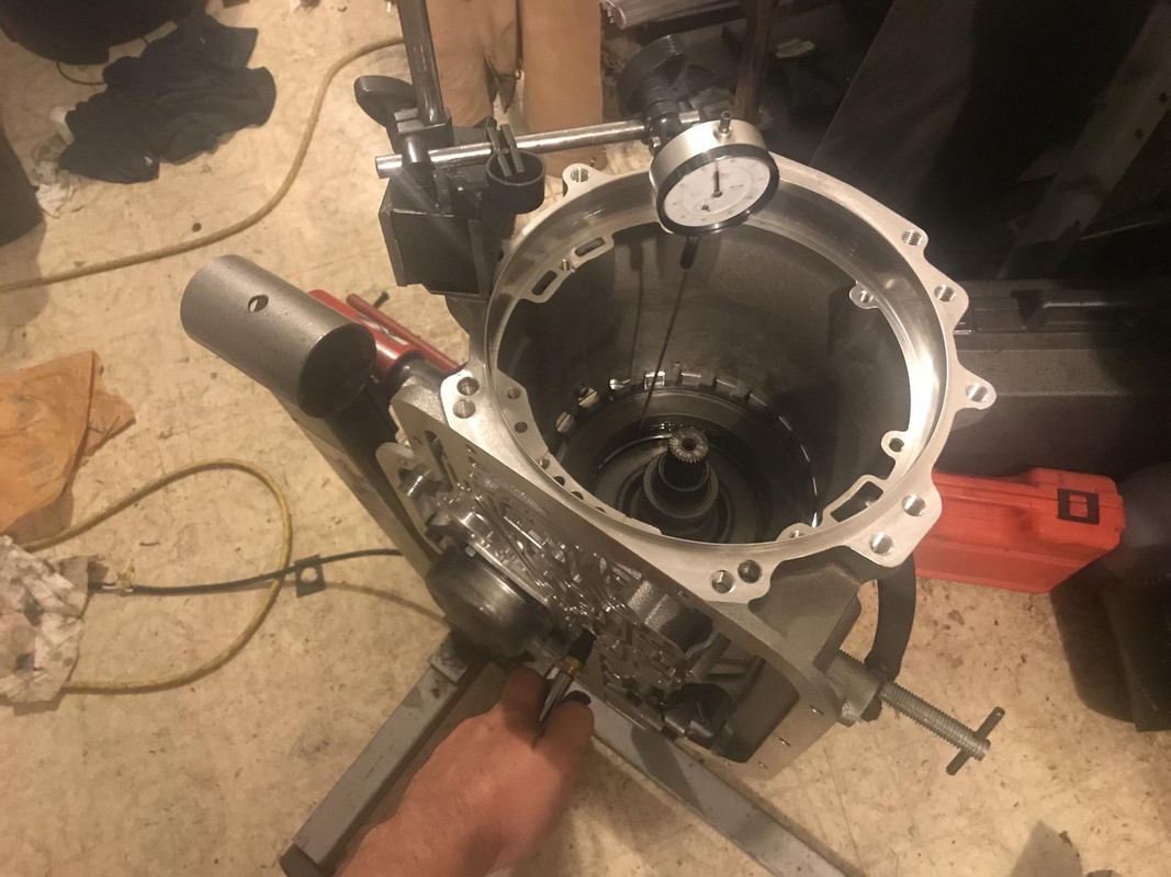
Here is all the guts of the trans assembled out of the case to check thrust clearances
It took an infuriating long time to get this all assembled correctly. I started this before I rebuilt the engine. I had to stop because after getting the rear of the trans together it did not turn freely. The cage on the low roller clutch was bent and was causing a bind so I had to order a new one from ATI. While waiting I decided to put away all the trans stuff to rebuild the motor which also snowballed into a 2 week ordeal while I fixed stuff in there and waited for parts. While I waited on motor parts I rebuilt the diff and had to wait for a new gear set as the set I had ordered for it was fried. After getting all that out of the way the trans went fairly smooth minus a few problems of my own making.
I chased my tail for two days trying to figure out the rear end play. The rear end play would check out fine until I started putting the front of the trans together and then the rear would have no endplay and bind up. Turns out I was using the wrong snap ring to hole the center support in and the rear end play was .015" tighter than I thought it was. There was a discrepancy with the instructions that came with my transbrake kit in how to plug the rear servo bore. The kit was not designed for an ATI case so the instructions could not be followed. After a couple days of back and forth on that I came up with my own solution plugging one of the fluid passages in the case and drilling and auxiliary vent hole to the rear servo.
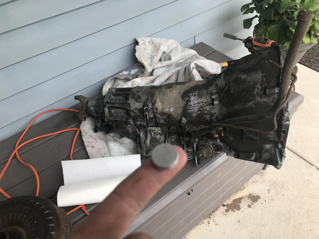
Also when I was doing final assembly putting the pressure regulator spring in the pump I launched the bore plug out the end of the pump at mach 2. I looked for that plug for a solid 8 hours including stripping the shop bare and setting everything out in the yard and never found it. I finally decided I could use spare parts anyway so I drove and hour to a junkyard in central minnesota to get another core transmission.
Entire day lost over this little plug
Naturally I found the plug the next day laying in my bushing driver set
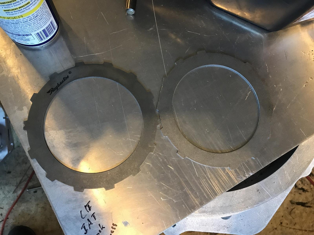
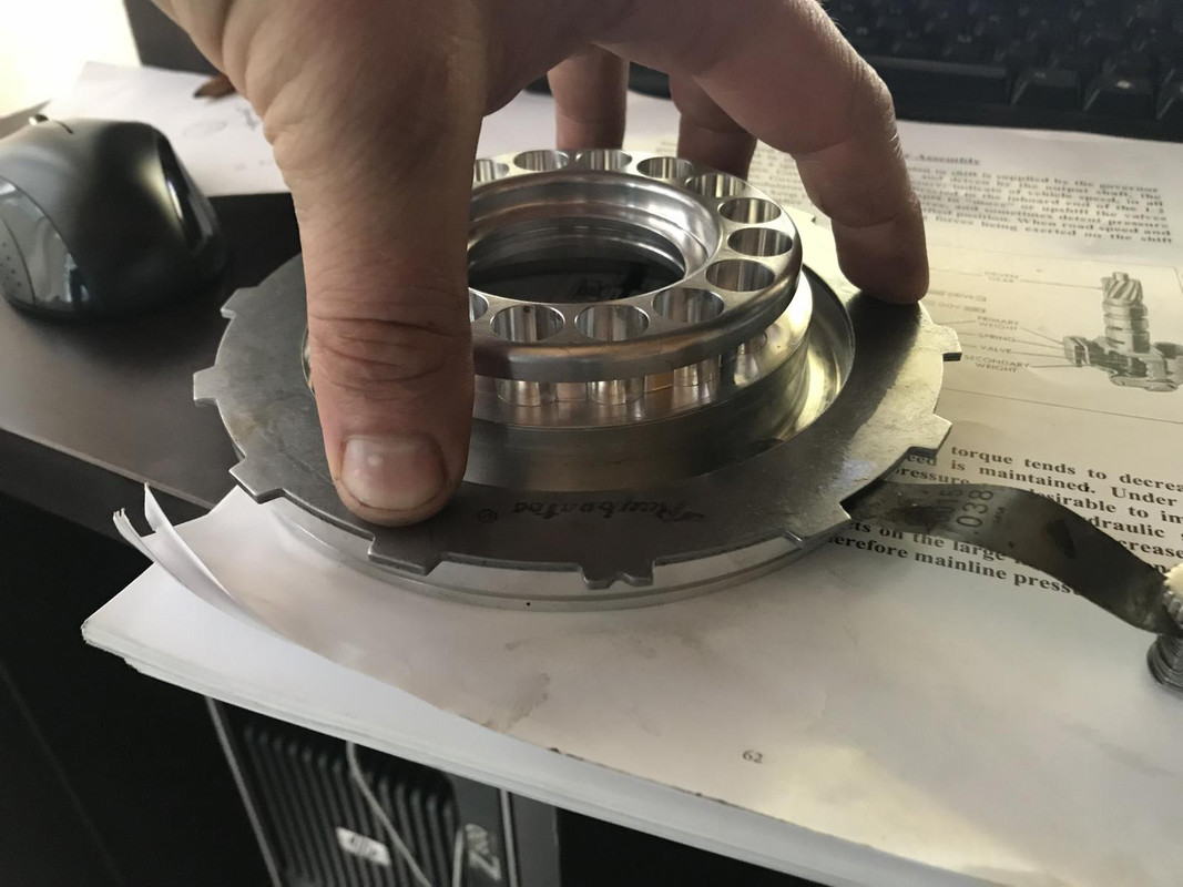
One of the little mods I did was to track down a set of clutch steels with all of the drive tabs intact. The stock steels (right) do not have all the drive tabs intact as a way to identify their thickness. The result is only 10 tabs making contact with the drum which put undue wear on the aluminum direct drum and will eventually make the drum unusable. I was able to find these raybestos ones (left) with all 14 intact. I replaced the steels that came in the ATI drum with these.
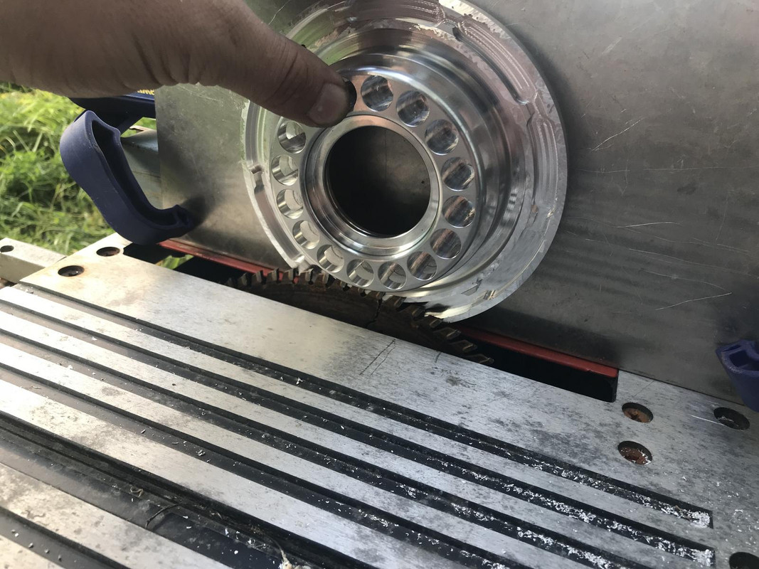
The new steels and clutch combo where slightly thicker than the originals so I had to remove the apply piston and reduce its working height to gain back that clearance
Believe it or not I did this on a table saw and kept the surface parallel to within .002"\
Its also flat to within .001"
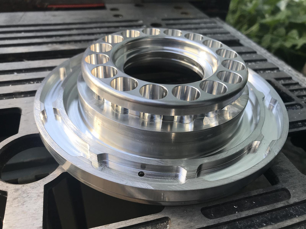
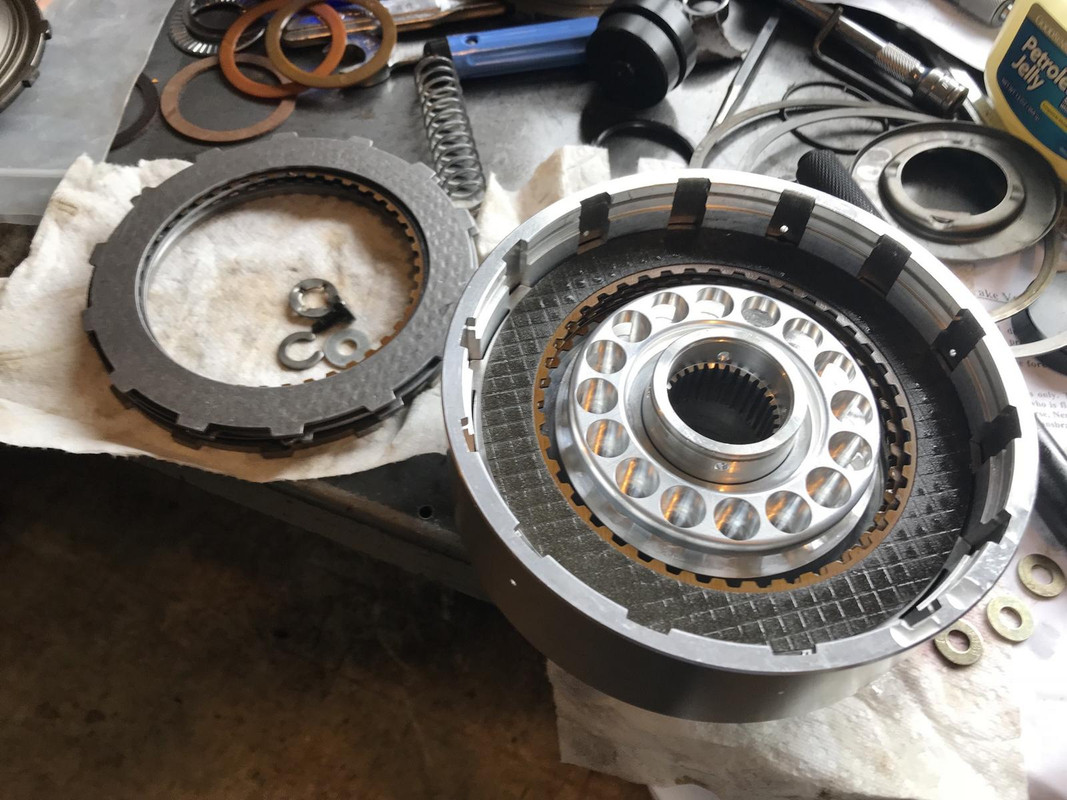
assembling direct drum
installing apply piston and release springs in forward drum. I also needed to machine the forward apply piston to height.
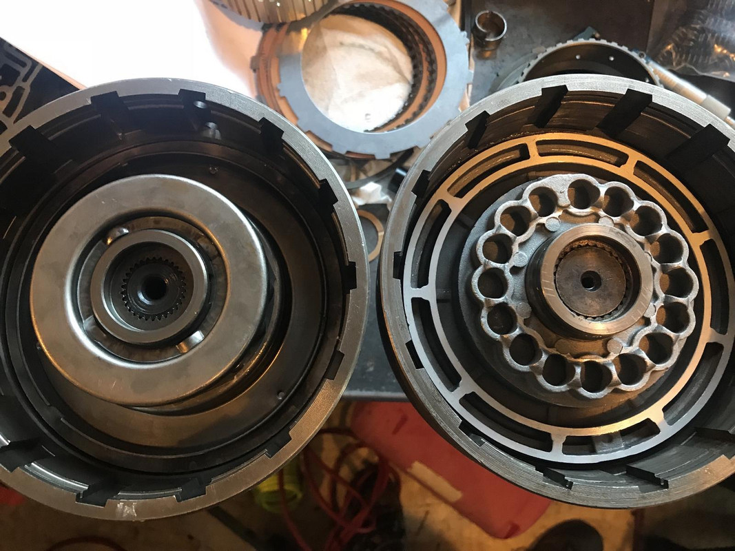
Stock forward drum with stock input shaft on left, ATI forward drum and input on right, note the spline size in the center
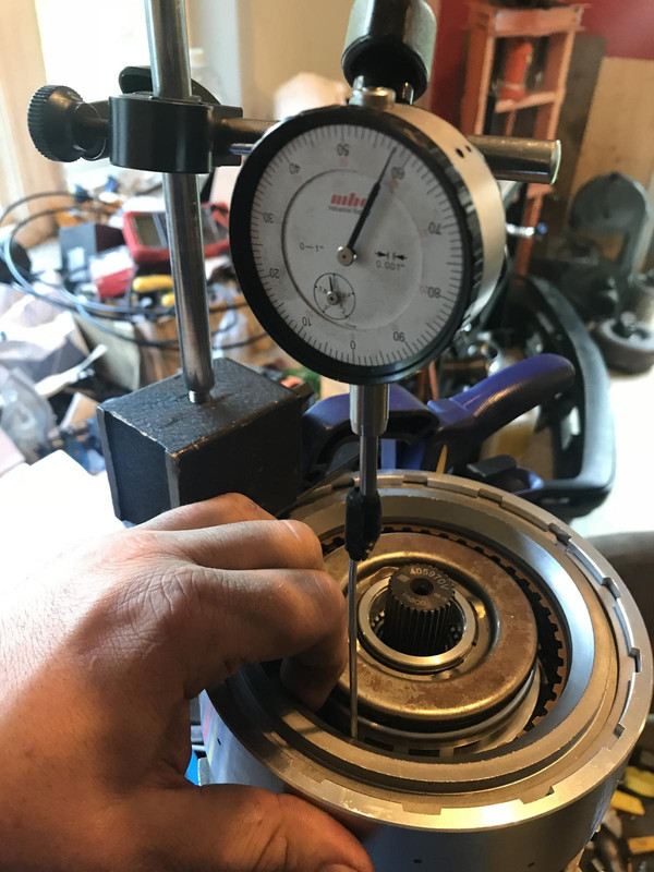
checking intermediate clutch clearance. It was .045" with no adjustments needed. These are custom clutch plates that are needed because of the oversize 36 element sprag used on the ATI direct drum
checking direct clutch clearance. Direct clearance set to .070" and forward to .065"
The forward clutch hub is rollerized so I was able to improvise some shims to lift it up and make it ride on the direct drum instead of the intermediate shaft, so now the intermediate shaft can float. This thrust on the direct drum should also help to keep the direct drum from running parallel to the drivetrain
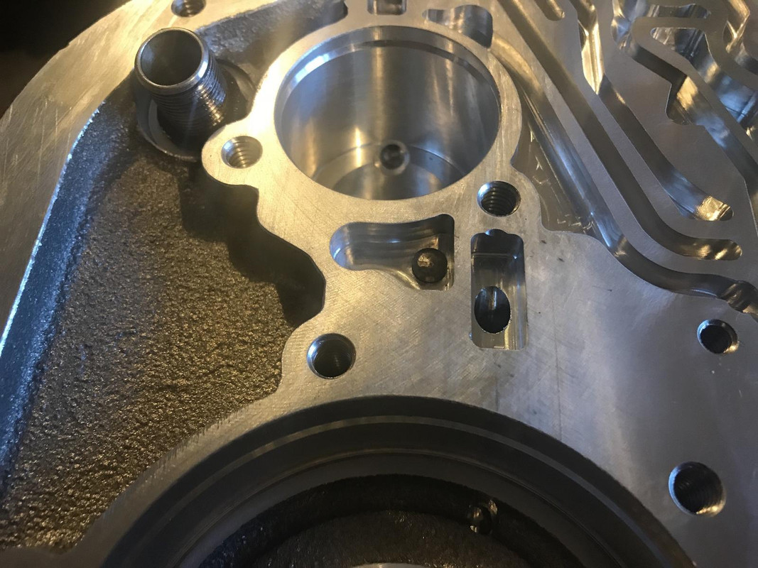
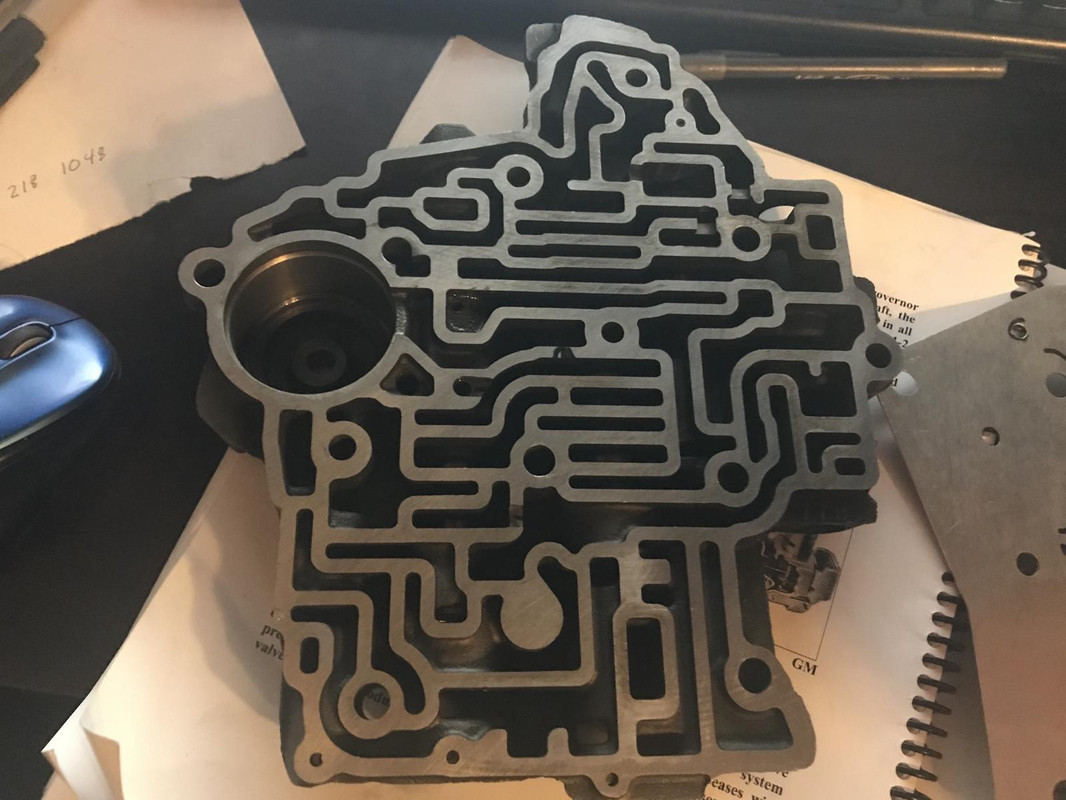
This is the CK transbrake valve body. I spent a couple days studying all the passage ways in the case, seperator plate, and trans to figure out all the fluid passageways. Its a pretty ingenious design. You can see some of the fluid passage ways that are machine into the stock casting.
transbrake valve body and filter in place. After installing the transbrake solenoid in the trans I found the transbrake scheduling valve was sticking in the bore which would have prevented the transbrake from releasing. After identifying where the tight fit was it took about an hour of spinning the valve in a drill to get the valve to move freely in the case.
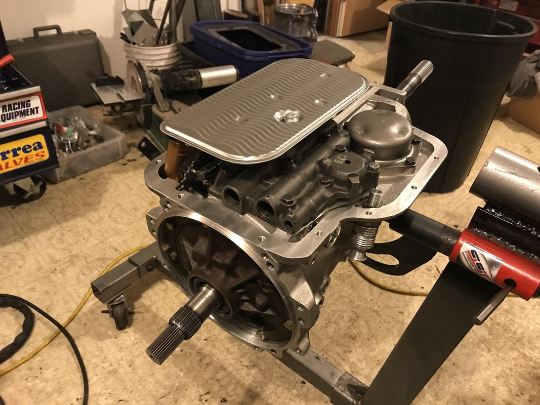
assembled trans
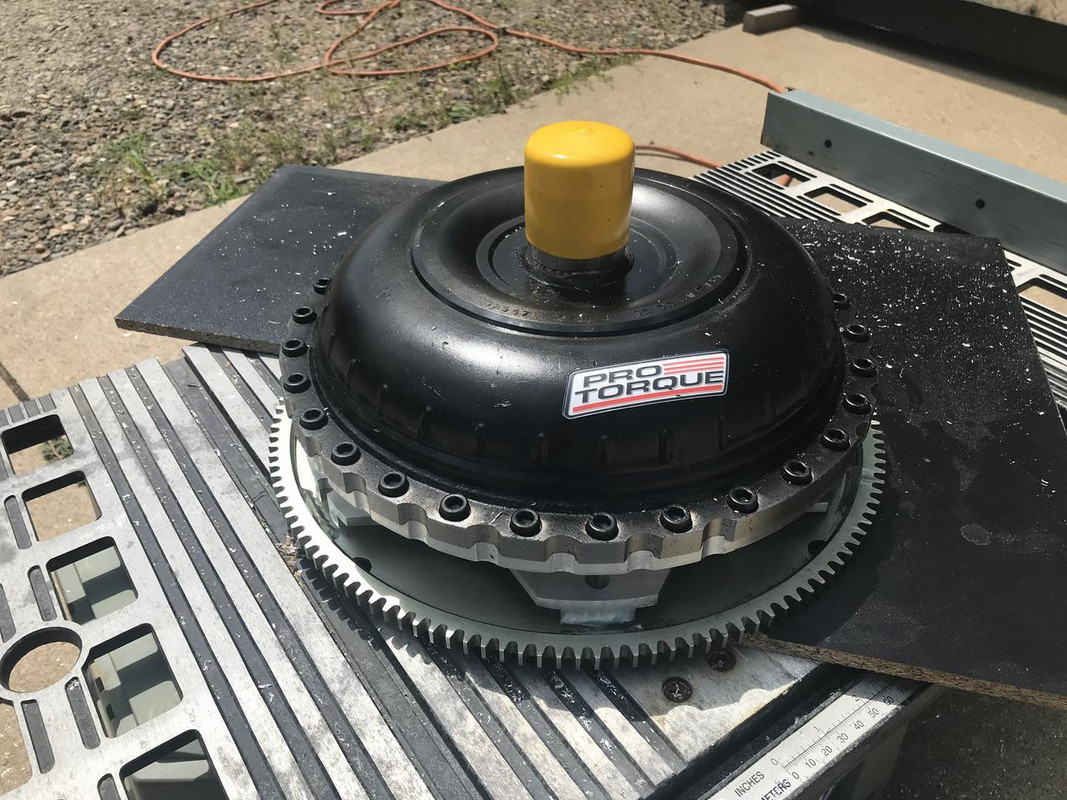
Torque converter is a billet 9.5" from Pro Torque
86 325es, 2.8L m50, S476sxe, ProEFI 128 ecu, e85, solid rear axle, TH400 trans, 28x10.5w slicks, zip ties, popsicle sticks, tape
best time 9.06 @ 151.8 mph, best 60 foot 1.30
Member
I hate to say it, but out of all of this mad scientist awesomeness, the thing that really gave me the "Ah HAH!!" moment was when I saw your trans vice bolted to the side of your engine stand upright tube. GENIUS! (why didn't I think of that??) Lol
Ring Master
Very nice. These auto setups are pretty wild. The 1-2 is a bit unreal.
Sent from my iPhone using Tapatalk
1989 535i - sold
1999 M3 Tiag/Dove - sold
1998 M3 Turbo Arctic/black - current
2004 Built motor TiAg/Black - Sold
2008 E61 19T Turbo-Wagon - current
2011 E82 135i - S85 Swap - current
1998 M3 Cosmos S54 swapped Sedan - current
1998 Turbo: PTE6870 | 1.15 ar | Hp Cover, Custom Divided T4 bottom-mount, 3.5" SS exhaust, Dual Turbosmart Compgates, Turbosmart Raceport BOV, 3.5" Treadstone Intercooler, 3.5" Vibrant resonator and muffler, Arp 2k Headstuds | Arp 2k Main studs | 87mm Je pistons | Eagle rods | 9.2:1 static compression, Ces 87mm cutring, Custom solid rear subframe bushings, Akg 85d diff bushings, 4 clutch 3.15 diff, , Poly engine mounts, UUC trans mounts W/ enforcers, 22RPD OBD2 Stock ECU id1700 E85 tune, 22RPD Big power Transmission swap w/ GS6-53
M54B30 Inside
Wow!!!
That is an incredible adventure with the transmission!
Thank for sharing.
Member
UNREAL!!!! This is up there with amazing. You're a complete stud. I am in awe.
TEC-3R, T4 GT40, WISECO, EAGLE, SUPERTECH, O-RING'D "FRANKENSTEIN" STROKER.
Light Fires N Burn Tires
Your table saw hack is pretty cool!
Should try and get a good deal on some used machining equipment. Would sure help with all of your cool projects.
u owe my mule an apology
Man I know it, I really need a CNC and like a 36" lathe. I don't have any room in the shop for it though. Even a bridgeport would be a massive help.
86 325es, 2.8L m50, S476sxe, ProEFI 128 ecu, e85, solid rear axle, TH400 trans, 28x10.5w slicks, zip ties, popsicle sticks, tape
best time 9.06 @ 151.8 mph, best 60 foot 1.30
 Posting Permissions


 Reply With Quote
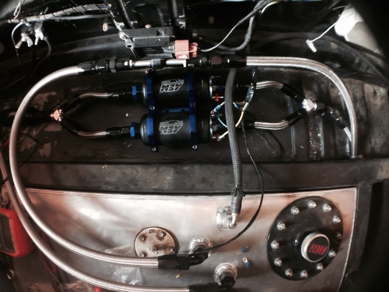


Bookmarks