
 Member
I would lean towards the straight E85 build to keep it simple. Just a thought, instead of milling the block down, maybe get an MLS and take some layers out of it? Not sure how many layers are in the standard size but the one's I've used have a few .010 layers. It would probably seal better and less chance of leakage through with less layers.
My manifolds powering 8sec and over 1000rwp cars
Home of the highest HP stock M30 in the world 550rwhp/622rwtq
1/4 mile---> 9.81 @138 C4 Auto
10.08 in car vid --->https://youtu.be/OiinFhUomjg
Dyno vid... http://www.youtube.com/watch?v=C7aM7..._order&list=UL
Member
Or just order a custom one. They come in nearly any thickness.Originally Posted by good & tight

u owe my mule an apology
The ideal solution would be to get a set of m52b25 pistons, as then I would only need to shave like .030" instead of .060", but I can't find any for a reasonable price and I'm tired buying junk pistons. At this point the block is worth less than an MLS and and I can mill it for nothing since I have the flywheel cutter already. Plus I really hate special order parts, seems like I always get stuck waiting 6 weeks for a part thats supposed to take 3 days. I spent the evening reading back up on the water injection thing and I think I'm gonna go for it. One last thing I need to check is piston to valve clearance. I did some talking with Paul Burke on this whole stupid project awhile back and he recommended about where he thinks I need to be for cam timing so before I make up my mind I need to check to be sure I have enough valve pocket to be where I want with that. I have mood swings like a pregnant woman though so stay tuned for flip flopping. I'll be in Boston all next week on business so I won't get anything done till next weekend.
86 325es, 2.8L m50, S476sxe, ProEFI 128 ecu, e85, solid rear axle, TH400 trans, 28x10.5w slicks, zip ties, popsicle sticks, tape
best time 9.06 @ 151.8 mph, best 60 foot 1.30
u owe my mule an apology
update:
I have been doing some 3d design work for a few people on the side so I haven't had any time to work on the car between that and my real job. I made up my mind on what route to follow. I'm going no guts no glory, 12:1 compression on E85 and water meth. After mulling in over I decided the water injection would be highly beneficial in keeping the cast pistons cool and alive anyway so it was worth the added complexity and expense. I don't really care about longevity here so if it fails, so what, I'll make another one. So I've started piecing stuff together to build a water meth system. I will probably either run a single nozzle with pulse width modulation solenoid off the mega squirt, or just run a simple staged system with two nozzles controlled by megasquirt.
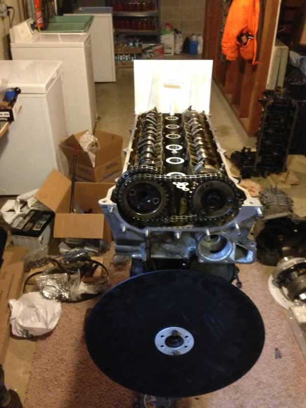
I also decided that the stock gasket would not be optimal because the thickness will actually trap a large dead space around the piston at top dead center, and will require me to mill alot of material off the block. So instead I've ordered a cometic 85mm gasket in a .027" thickness, which is the thinnest they list for the application. Lets hope I can reuse it a few times and get my moneys worth out of it. I also took some time the other night to mock up the cylinder head on the block to see exactly how much quench pad I have to work with. I think it will be enough to get the job done. Also note the tight clearance of the valves to the 84mm bore.
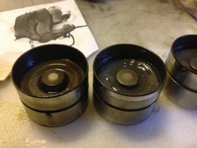
I'll be using the m52b28tu pistons and m50 vanos rods. I got these pistons for free with the crankshaft about 6 years ago and never thought I would use them so they are a little beat up, but they should work. I had lost a couple of the pins so I pulled the pins out of the m54b25 pistons, which luckily are the same length. I felt the pin fitment on these was a bit too tight so I spent a couple hours with some 800 grit paper polishing the pins and hand fitting the pin bores till I got the feel that I was looking for.
I've got the block mocked up now with pistons in there final positions to measure piston height. I got a high of .028" below deck and a low of .031" below deck. Once I check piston to valve clearance I will tear it down and will be milling .013" off the block then honing off and additional .002" to arrive at a target piston to head clearance of .040".
Final number for compression will be,
bore = 84mm
stroke = 75mm
cylinder head = 31.3cc
piston valve relief = .8cc
head gasket = 85mm x .027"
piston to deck clearance = .013"
compression ratio = 12.0:1
Last edited by someguy2800; 11-15-2017 at 03:33 PM.
86 325es, 2.8L m50, S476sxe, ProEFI 128 ecu, e85, solid rear axle, TH400 trans, 28x10.5w slicks, zip ties, popsicle sticks, tape
best time 9.06 @ 151.8 mph, best 60 foot 1.30
Member
Hey - since you're going all out whacky style... want some forged aluminum rods?
Member
Tell me you still have those rods! I want them so bad! I found that thread you made about the set you got ahold of and iv been looking for a set ever since!
Member
I do still have them lol. I am mentioning them to someguy2800 so if he's at all interested bear with me but I realize I am never going to use them. I wanted to play with a 75mm stroke aluminum rod screamer in the E30 I was building but I ended up just using a stock motor to get it on the road. If either of you guys are interested shoot me a PM.
Member
Yea I am in no position to buy them from you at the moment Anyway ineed to get my first build running first I just saw the post and got excited. But I may be in contact with you in a few months.
u owe my mule an apology
That is in the plan for the next motor. Don't have the money right now. How much do you want for them?
86 325es, 2.8L m50, S476sxe, ProEFI 128 ecu, e85, solid rear axle, TH400 trans, 28x10.5w slicks, zip ties, popsicle sticks, tape
best time 9.06 @ 151.8 mph, best 60 foot 1.30
Member
Cheap dude I'd take $200
I believe they are M20 or M30 size big ends, not positive. Could measure if you're interested.
Troll level: Master
Damn I thought 11:1 was good for turbo, and now im reading 12:1 maybe I shouldve gone a bump higher.
Can't wait to see track times and numbers from this all stock setup.
24v all day
u owe my mule an apology
At that price I an definitely interested. Can you measure big end, pin boss, and length quick? Do you know who made them? I'm gonna guess Howard's?
86 325es, 2.8L m50, S476sxe, ProEFI 128 ecu, e85, solid rear axle, TH400 trans, 28x10.5w slicks, zip ties, popsicle sticks, tape
best time 9.06 @ 151.8 mph, best 60 foot 1.30
Member
Yeah I will measure tonight. They're older generation Howards. They have a Howard PN# but Howard has no idea what they were spec'd for lol.
They're in mint shape and I x-ray'd them at work.
I'll measure in a bit.
u owe my mule an apology
Spent the whole day playing with camshafts and taking measurements. The recipe for the top end is a ported non vanos head, modified to accept a vanos unit, m50 vanos lifters and trays, an m54b30 intake camshaft, and an m50 non vanos intake cam in the exhaust side. Since this is obviously not a normal setup, I had to go through all the legwork to check piston to valve clearance and whatnot. While I was at it I also mapped both cam profiles.
So to start I installed my timing wheel that I 3d printed. It is 14" in diameter and bolts directly to the front hub where the harmonic balancer goes. I simply use a bolt in one of the timing cover holes as a marker
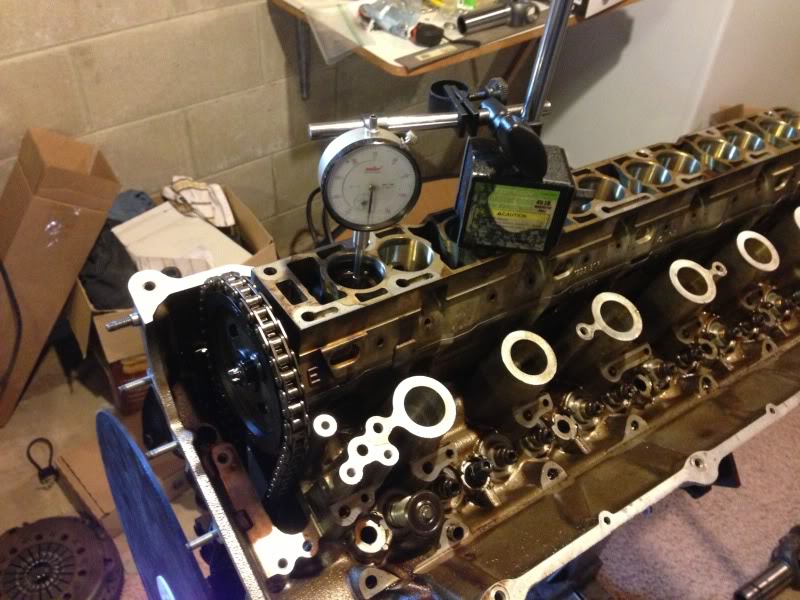
Next to check the piston to valve clearance I assembled the head with 2 intake and exhaust valves with light springs and installed the chains and tensioners. In order to eliminate the lifters from the equation I took a couple spare lifters and potted them with epoxy to lock them in position and keep them from moving under spring load. This leaves the valves hanging open .045" which is perfect because as the motor sits this is essentially .060 of extra length which is my minimum piston to valve clearance.
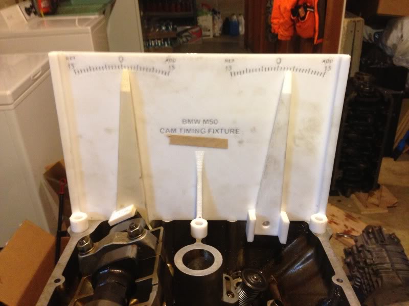
Now to check the clearance I installed my camshaft timing fixture that I designed. It slips over the back of the cams and will read the camshaft angle from -15 to +15 in camshaft degrees. The lever on the exhaust side already has the correct offset built in to run a non vanos intake cam in the exhaust side, at a m50 vanos lobe center angle. Please note that cam timing is normally expressed in crankshaft degrees, which is twice as much as camshaft degrees. So if someone references advancing the intake cam by 6 degrees, this means that the cam angle will actually change by 3 degrees. Likewise if you changed camshaft angle by 6 degrees, this would be expressed as 12 degrees advanced. Got it? With the timing fixture in place checking interference is easy. Just rotate the crank where you want to check, then rotate the cam by hand untill you feel the valve contact the piston.
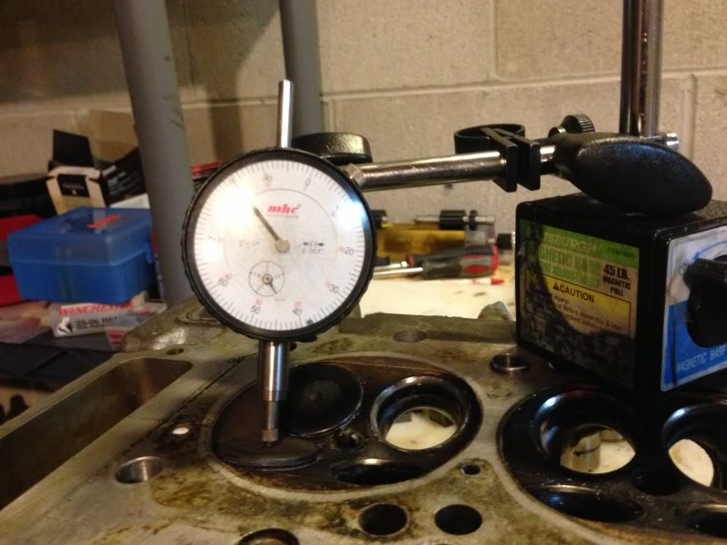
Now to map the cam profiles and find the lobe center angles. Here is a really neat trick for getting an indicator on the cam. If you've ever tried its near impossible to get an indicator down on the lifter with the cam in place to measure lift. So here is a trick to how to do it. Take a spare lifter bucket and flip it over upside down and put it on top of the cam. You should be able to get it all the way down on top of the other with no gap. Then just drop a lifter in the top and you can place an indicator on the top to read. Thanks to Paul Burke for telling about that trick.
So here is what I got for results;
non vanos intake cam in exhaust side
installed at same center angle as a vanos exhaust cam
LCA = 102 deg
lift = .379"
duration @ .005" lift = 237 degrees
duration @ .050" lift = 200 degrees
lift vs crankshaft angle
.005" = 140.5
.020" = 149.5
.050" = 157.5
.100" = 167.5
.150" = 177.5
.200" = 188
.250" = 198.5
.300" = 210.5
.350" = 230.5
.378" = 253
.378" = 262.5
.350" = 286.5
.300" = 304.5
.250" = 317.5
.200" = 329
.150" = 338.5
.100" = 347.5
.050" = 357.5
.020" = 365
.005" = 377.5
noM54b30 intake camshaft
installed straight up
LCA = 122.5 deg
lift = .381"
duration @ .005" lift = 237 degrees
duration @ .050" lift = 201 degrees
lift vs crankshaft angle
.005" = 5.5
.020" = 14
.050" = 22
.100" = 33
.150" = 41.5
.200" = 54
.250" = 63.5
.300" = 76.5
.350" = 94
.378" = 112.5
.378" = 132.5
.350" = 150.5
.300" = 167.5
.250" = 181
.200" = 192.5
.150" = 202
.100" = 211.5
.050" = 223
.020" = 232
.005" = 242.5
While testing for interference I also noted the minimum possible lobe center angle for the intake and exhaust cams before interference becomes a problem, so I know the safe range for future cam timing adjustments. I found that the exhaust cam can be retarded to a minimum LCA of 100 degrees BTDC, and the intake cam can be advanced to a minimum LCA of 94.5 degrees. Since I will be using vanos, which is supposed to advance the intake cam by 12 degrees, this mean I can run a minimum lobe center angle of 106.5 degrees, and still use the full 12 degrees of vanos travel. Both number are well within what I plan to start with for initial timing.
I am planning on starting with a LCA of 112 degrees on the intake and 111 on the exhaust. This gives the following valve events.
IVO = 12 deg BTDC
IVC = 33 deg ABDC
EVO = 31.5 deg BBDC
EVC = 11.5 deg ATDC
There will be a ton of power left on the table due to the tiny cams, but there arn't any options available besides for an s50 intake cam, which I don't want to do for my own stupid reasons. I would really like to try a set of Cat Cams 282-274 non vanos cams or get Paul Burke to spec a custom grind for me, but that will probalby have to wait for the next motor.
Next on the list is to finish up the block and assemble the bottom end, then finish porting the head and install it.
Last edited by someguy2800; 07-12-2018 at 12:02 PM.
86 325es, 2.8L m50, S476sxe, ProEFI 128 ecu, e85, solid rear axle, TH400 trans, 28x10.5w slicks, zip ties, popsicle sticks, tape
best time 9.06 @ 151.8 mph, best 60 foot 1.30
Cantry Member
For checking my valve clearances I made a steel plate that bolts down to the head over the spark plug holes for mounting the magnetic base to. Then I took the dial indicator, unscrewed the point from it and made an extension out of SS welding rod and screwed it in. The extension fits between the lobe and the bearing cap down to the lifter. It works for both cams.
Sent from my GTX3582R
'97 M3, Estoril blue, 2 dr, euro 6-spd, EFR 9180 divided T4 .92 IWG, RK tuning, CP 8.5:1 pistons, Eagle rods, Schrick cams, L19 11 mm ARP studs, O-ringed block, Supertech stainless/inconel valves, Supertech springs & Ti retainers, ported head, S54 oil pump/pan, 80 lb. injectors, OBD1 intake manifold, Steedspeed twin scroll T4, 3.5" SS exhaust, eBoost2 EBC, HFS-4 W/M injection, AEM Failsafe, Zeitronix data logger, Racelogic TC, OpenOBC w. ethanol %, Ireland Eng. engine mounts, UUC black tranny mounts w. enforcers, UUC twin disc feramic, ARC-8's, MCS 2-ways, Z3 rack, Rallyroad strut bar, X brace, Eibach sway bars, Ground Control LCAB bushings, Bimmerworld RTAB's, Powerflex subframe bushings, 210 4-clutch LSD, Stoptech BBK, titainium shims, steel braided lines, brake cooling ducts.
Member
Hey man I didn't get a chance last night to measure those rods. I have to do some work tonight so I will do that tonight.
Interested in selling that cam timing wheel and cam alignment lever setup?
Last edited by 5mall5nail5; 06-03-2013 at 08:00 AM.
Member
Checked the forged aluminum rods. They've got 0.8640" wrist pins (22mm), and 1.889" (48mm) big ends. They're 0.8540" (21.65mm) thick. They've got ARP 2000 hardware in them (bolts).
Last edited by 5mall5nail5; 06-03-2013 at 09:23 PM.
Member
What's the length of it?
Member
Damn man you have some serious talent... God bless you! haha
Luchador
Nice!
I need to get a dial gauge setup like that to measure out my cams! You are inspiring me to get off my duff and do it.
Member
Sorry, didn't edit post, got to make a FedEx run.
Perry,
Full vanos travel is 25 crank degrees.
I like what your doing here, when I get more time I will read through the whole thread.
Car is starting to grow on me also!
Paul
Last edited by paul burke; 06-04-2013 at 06:07 PM.
Member
Well, you're not the only one here as I too feel like doing something but can't. I don't have a project car or an engine to play around, yet I really feel like I want to do something.
u owe my mule an apology
Thanks Paul! Glad you like it. I hope in the future when I get some more money to play with I'll have you making me some pistons and cams! Thanks for the heads up on the vanos, I was planning on checking that during assembly. I might have to limit that. I know it really needs more duration but what do you think of my lobe centers? I came up with these number by playing with desktop dyno.
86 325es, 2.8L m50, S476sxe, ProEFI 128 ecu, e85, solid rear axle, TH400 trans, 28x10.5w slicks, zip ties, popsicle sticks, tape
best time 9.06 @ 151.8 mph, best 60 foot 1.30
Member
Once I get my VANOS head motor going I am going to try and see if vanos is PWM controllable. I think with a big enough hole in the oil system we could make single vanos variable...
u owe my mule an apology
Last edited by someguy2800; 06-05-2013 at 12:22 AM.
86 325es, 2.8L m50, S476sxe, ProEFI 128 ecu, e85, solid rear axle, TH400 trans, 28x10.5w slicks, zip ties, popsicle sticks, tape
best time 9.06 @ 151.8 mph, best 60 foot 1.30
 Posting Permissions


 Reply With Quote


Bookmarks