
 Member
No, not mail order forever. There's a good shop about 1.5 hrs away from me, but they don't have mobile capability, so I would have had to drag the car out there on a trailer, have them flash it to remove VATS and etc, then fire it up for the first time in their shop (no way). My plan is to do a mail order to get the car running and driving and then take it there to be dyno-tuned accurately.Originally Posted by James39

Steve seemed like a nice guy, but didn't really give me the answers I needed in the email. When I called the shop he works at to get a hold of him, they told me he only actually works there nights and wouldn't be able to respond until tonight or tomorrow. I'll have to wait and see what he says.
In the meantime, I already spoke with Speed Inc out of Schaumburg IL, and they said they'd have no problems tuning for my injectors, compression, etc etc as well as taking care of all the auto to M6 stuff.
Black Sheep
Have you considered tuning it yourself? It's fun, and you can do whatever you want.
'99 BMW 540i6 L33 5.3, PRC Heads, E-force supercharged
http://forums.bimmerforums.com/forum....php?t=1674320
Still has a E39
Supporting Vendor
For what its worth, Steve is a good friend of mine and a clown he is not. He knows his stuff and I would trust his words over anyone's.
Member
I have considered it, but at this time I'm not really attracted to the cost of software, learning curve to get it right, and time invested. :/ Just want it up and running at this point. In the future if/when I go with a bigger cam/etc, it'd make sense to do it.
Black Sheep
Send an email to this guy: http://www.pcmcalibrators.net/ He's the one that enabled 12v AC request in my truck OS, he knows them inside and out.
'99 BMW 540i6 L33 5.3, PRC Heads, E-force supercharged
http://forums.bimmerforums.com/forum....php?t=1674320
Member
FWIW, I just got my pcm back from the owner of lt1swap.com. He did all of the things necessary to run it on four wires and he changed the tachometer output to 6cyl. He turned it around real quick and it was $75 with return shipping included. Hopefully I should know if it works or not by the middle of next week!
92 325i LS1/T56
Member
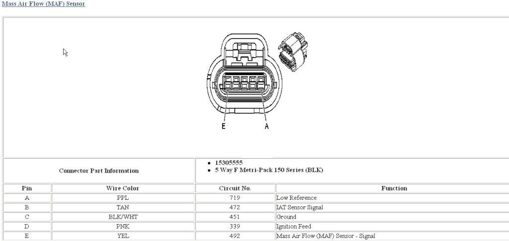
for whatever reason, on my MAF pigtail, wire "D" is clipped.
I'm going to assume I need this, will any 12V+ key on signal work?
Where did that wire go on everyone else's? My coloring scheme is different, it goes:
A - YELLOW - MAF SENSOR SIGNAL
B - PINK - TO 12V+ FROM FUSE BOX
C - BLACK/WHITE STRIPE - GROUND JUNCTION IN THE HARNESS
D - TAN (CLIPPED) - ?
E - TAN - LOW REFERENCE IAT
Last edited by nsogiba; 04-19-2013 at 11:27 AM.
Member
The tan wires are for intake air temp readings for the PCM, a lot of people hook up a remote IATS, I run mine down by my filter.
Member
According to that diagram my tan wire in Pin D on the MAF pigtail is ignition feed. I traced the OTHER tan wire to the PCM and it's C2 Green 57 Low Reference (IAT). So, this tells me the MAF housing also is a combination IAT sensor. I don't want to run a remote sensor just yet--where does the other tan wire go to run the IAT in stock form?
Member
It's a 2 wire sensor, both tan wires are for IATS. That's the way my MAF is. Pink is power, black is ground, yellow is signal to PCM for MAF readings. I'd say the diagram is wrong
Member
Okay, I think I know where I went wrong. Yellow, pink, and black all make sense since they have the same harness destinations (even though the plug locations A-E are different).
However: one of the tans goes to 57 BLK 552 Low Reference (IAT), which is fine. A quick CTRL-F of the LT1swap site for 2004Vortec shows that the other clipped tan could only go to 25 TAN 472 IAT Sensor Signal. I'll add the pin back in (no idea why it's gone)!
Thanks for the help JF!
- - - Updated - - -
where does the following plug in?
C1 Blue
74 YEL 410 ECT Sensor Signal
80 BLK 407 Low Reference (ECT)
On my harness it's a small 2 pin Weatherpak style connector, wires are tan, and yellow.
Last edited by nsogiba; 04-19-2013 at 02:25 PM.
Member
So this pigtail obviously goes to the GM temp sensor, which is long gone—its place has been taken by the BMW temp sensor of the same size. After doing some reading, it looks like the PCM still relies on the OEM GM sensor for input to be able to help the engine run right. The driver’s side front area of the head still has an available water port, blocked off—is it a good idea to pick up a factory GM sensor and use it in that hole? I can’t see it hurting anything but my wallet.
Another quick question: I installed the LS6 throttle body that came with my LS6 intake, and swapped over the idle air control sensor as well as the throttle position sensor from the truck throttle body. I didn’t see anything in the harness when stripping it that was related to these two. What am I missing? Surely the PCM will need input from these two.
Last edited by nsogiba; 04-22-2013 at 08:49 AM.
Black Sheep
My gm sensor is in the drivers side front, my gauge sener is in pass. side rear.
This page describes DBC wiring: http://lt1swap.com/cable_conversion.htm
'99 BMW 540i6 L33 5.3, PRC Heads, E-force supercharged
http://forums.bimmerforums.com/forum....php?t=1674320
Member
outstanding...thank you!
Member
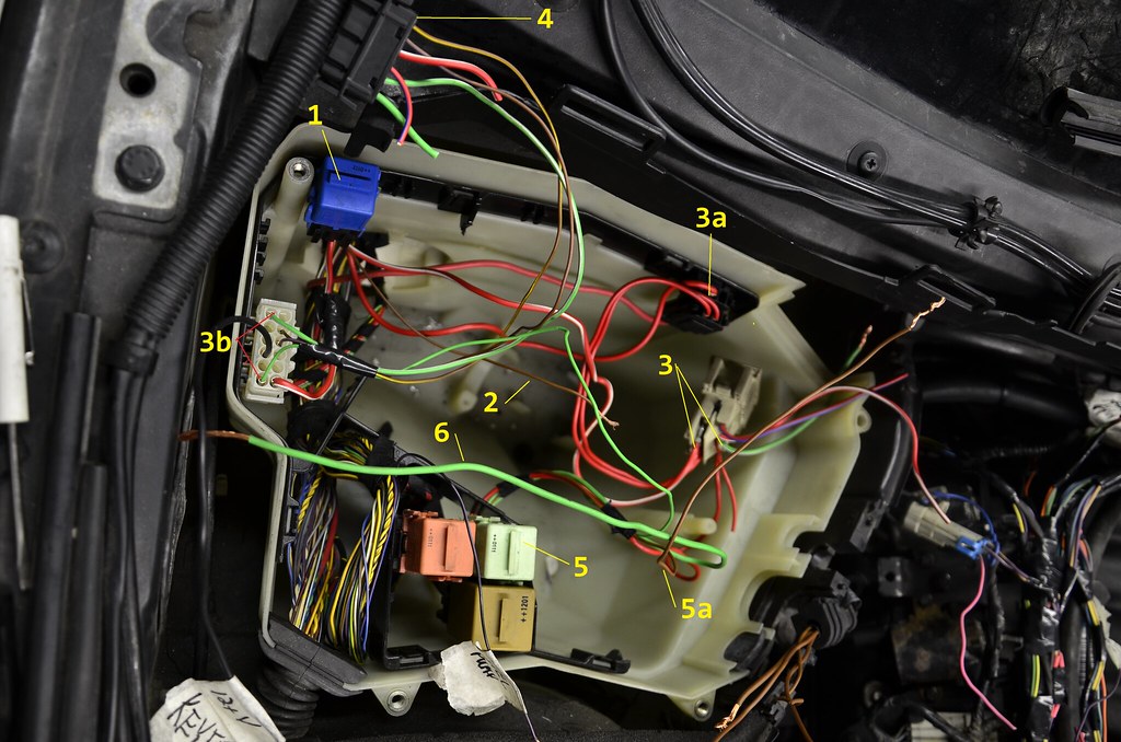
ok, the e-box is really kicking my ass. not sure if i'm just burnt out from working on this thing so long or just frustrated for being so close to starting it.
-is #1 my DME relay? it has power supplied to it directly from the power source (3a), so i would assume so.
-#2 is obviously the ground wire for that relay, but is this the wire that is hooked up to the new "DME switching relay" that is triggered by KEY ON 12V+, which converts polarity?
-The 5-circuit mini fuse holder does not have any KEY ON 12V+ wires. They're all hot all the time, even with key off. This makes sense, since 2 of the wires that feed it come directly from power supply 3a. I was able to find 2 KEY ON 12V+ wires, shown at 3b. Is it acceptable to tap these for every single signal that needs KEY ON 12V+? I mean, I would assume all the sensors (O2 sensors, CMP, CKP, etc) need KEY ON 12V+, but it can't be ok to pull all my power from there. The only other reasonable option I see is pulling power from the 5 slot fuse holder to each sensor, and then the sensor only actually turns on when the signal wire/ground/whatever other wire in the pigtail activates, completing the circuit. Bear with me as this is all new to me.
-Do I still need the black plug shown at #4? Most of the wires in that went to dead end junctions.
-Is the light green relay at #5 my BMW fuel pump relay?
"The fuel pump is controlled by the DME, but also requires a ground to trigger it. So, I used yet another relay (connected to the GM PCM's + fuel pump relay signal) to convert that to a ground." So, is the ground wire at #5a the one that is hooked up to the new "fuel pump polarity converting relay", which itself is triggered by the GM PCM?
-What is the purpose of the light green wire at #6, which comes out of the above mentioned relay at #5?
Again pardon my frustration and the long message, just trying to finally end this wiring saga, or at least find out what's going on in the e-box.
Member
#5 should be the DME relay, fuel pump relay is in the trunk. Don't know what the blue relay is, don't remember that in my car. The black plug should be able to go... I'm sure one of the pros will chime in with a more detailed answer. Lol
Black Sheep
In my car, the DME relay was activated by a ground signal from the DME.
The DME relay powered on 3(?) of the circuits in the fuse holder.
One or 2 of the remaining fuses was hot all the time, and I think the power came directly from that stud in the back corner of the ebox.
I reverse engineered everything I needed and left everything else alone. If I encountered any wires that I couldn't easily trace by eye sight where they went, or how they were turned on or off, I didn't touch them. If they were an obvious part of the engine harness that I stripped out, I identified and labeled them as they were cut or removed.
I think you're going to have to immerse yourself in the WDS for a day or so to figure out how the circuits were controlled in your ebox.
'99 BMW 540i6 L33 5.3, PRC Heads, E-force supercharged
http://forums.bimmerforums.com/forum....php?t=1674320
BMW + ASE Master Tech
For the dme relay.. It was removed or attached to the engine harness .. I just wired it in like WDS said but instead of making it ground controlled i made it power controlled since the gm PCM doesn't do that function. Just gave that terminal ground and for power just ran a wire to an empty spot on the fuse holder, added a fuse and done. All circuits are powered up like its supposed to. Same concept for the fuel pump relay.
Clint
2003 X5 4.6is - for sale
2006 X5 L83 5.3 6l80 swapped in progress - for sale
1999 528i 5.7L 4l60e swapped w/ 31 spline 8.8 cobra diff - for sale
2007 ZX-10r - sold
1987 R-10 SWB L83 5.3L 6L80e swapped
www.87chevy.com
Member
Okay, figured out most of what was giving me trouble in there.
Few quick questions regarding feeding the GM PCM power and grounds. i have a fairly good idea about them but maybe someone can just confirm if I'm right.
Grounds:
The following just need a simple ground from the body, right?
BLUE 1 BLUE 40 BLUE 27 BLUE 67 BLUE 24 BLUE 64 Green 40 Green 1
12V Power:
These need KEY ON 12V+, correct?
OFF RUN CRANK VOLTAGE 12V BLUE 75
IGNITION VOLTAGE BLUE 19
BATTERY POSITIVE VOLTAGE RED W/ WHITE BLUE 57 BATTERY POSITIVE VOLTAGE RED W/ WHITE BLUE 20
Last edited by nsogiba; 05-08-2013 at 09:30 PM.
Member
Brake switch signals and the X6021 connector under the hood. The schematic shows pin 25 as brake light test signal and pin 26 as brake light signal. I have brake lights but no measurable values on these two pins. Has anyone found changing voltages or resistances on these pins?
540i-LS3-TR6060 swap thread
BMW + ASE Master Tech
I'm at that same point WDS shows the the brake switch signal that goes to the dsc and others as a 12 constant and 0 when brakes applies but nope.. Not in my car or any other i tested.. The other test line is 0v and then 12v when brakes applied- opposite of what I need for the TCC circuit. I think I will just weld a bracket to the pedal and wire in a switch.. I don't know enough about transistors an circuits to switch the polarity an I don't wan to put a relay to switch it...
Clint
Sure it's 25 and 26.. In my schematic the pins were further apart. Like 25 and 28 or something
2003 X5 4.6is - for sale
2006 X5 L83 5.3 6l80 swapped in progress - for sale
1999 528i 5.7L 4l60e swapped w/ 31 spline 8.8 cobra diff - for sale
2007 ZX-10r - sold
1987 R-10 SWB L83 5.3L 6L80e swapped
www.87chevy.com
Member
My brake lights worked without the abs module having power, weird you guys don't have lights.
I don't have backup lights yet, but that's the only lights that I haven't hooked up.
Member
For a 1997 540, I found it to be 25 and 26. Wonder if it is year dependent. Neither connection has action on mine. You saw 12V on the test line?
Brake lights work fine. I'm looking for a 12V signal to feed to the ECU for the future cruise control implementation.
540i-LS3-TR6060 swap thread
Swagon
Just a heads up that my friend who owns the company I get all my stuff from said their gauge drivers are now officially for sale through Lingenfelter. You can program it to do any type of signal. There is also a relay port that can be used for triggering A/C in our cars. I plan on using one of these when I wrap up my build. I don't think it's on their site yet so you will have to call for pricing and availability. IIRC, they are around $250.
Member
Very interested in details.
 Posting Permissions


 Reply With Quote


Bookmarks