
 Member
Hi.. I have both radio and tuner but I am missing the cable between them. Have I understood it correct that I can get a used CD cable instead of buying the expensive new cable between the units?Originally Posted by Omega man 1969

Member
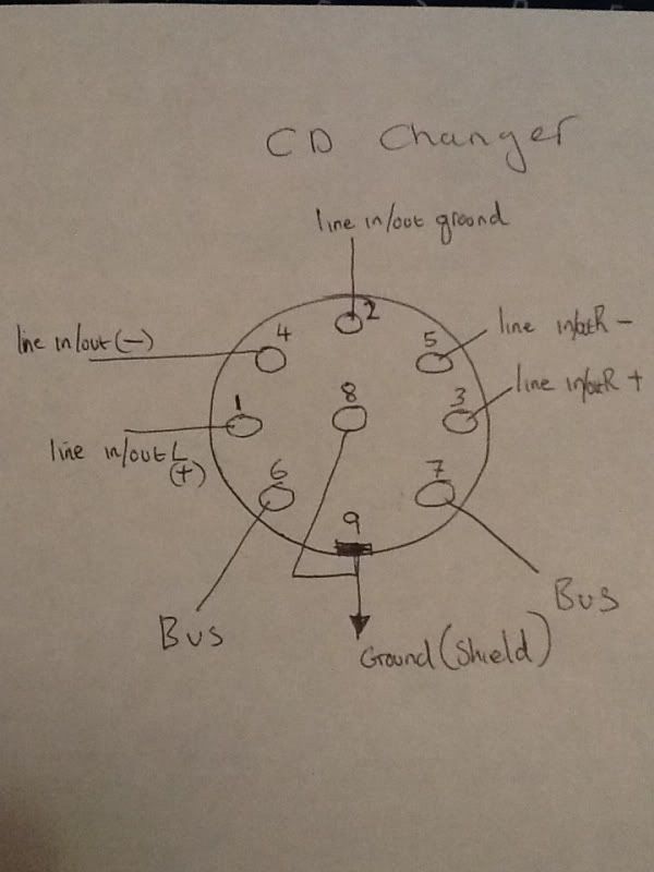
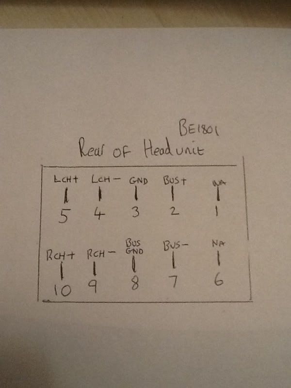
You have several options. 1) Get a used cable going straight from the headunit to the tuner. Seems to be the easy thing to find on junkyards, because factory wiring for BE1801 with 6CDC includes unconnected and unnecessary "headunit-tuner" cable (at least on my E34). 2) Get a 10CDC or CD-interface for 6CDC, and cables "headunit-cdc" and "cdc-tuner". 3) Make the cable yourself! Headunit side will have standard 2.54mm 2-row 10-pin socket, tuner side will have 8-pin DIN connector. 4x2 FTP cable seems to be a good choice. The only problem will be how to fix the headunit side socket int the 17pin connector.
Last edited by ilovemistakes; 04-13-2015 at 07:07 AM.
Manual Swapper
These cables are somewhat common since I believe Becker used the same ones on early-1990s Mercedes systems with the trunk-mounted tuner. I have these (for the Becker 10-disc) on my 93 MB 400E, and and they look identical to the ones on the BE1801. Check with the junkyards... I once got a set for free. They come up on eBay sometimes as well.

Member
Hi again.. Took some tome to find the 8 pin DIN but I got it now and would like to make my own cable..
This gives me some headache. If you look at Omega man's earliere post it looks like the pins go from 1 to 1, 2 to 2 etc. But if I look at the handwritten drawings the pins are different. What are correct?
Further more if I look at this page http://wp1016621.server-he.de/fotost/f01421/f01421.htm The pins and the pin number are different again.. Please help me :-)
1991 E32 750IL Highline Individual
1987 Alpina B11
Member
Just for closure so 2/7 Headunit and 6/7 RDS unit are BUS.. After these two are fitted I have control over the radio and it works fine but with Pixel error but for 20 Euro complete I am happy!
1991 E32 750IL Highline Individual
1987 Alpina B11
BMW E36 Expert
Surprised the 2450 mbus also supports ibus. Still extremely sad it has no id3/ibus message support. I hoped the external device would send the message and the unit just displays it, but as it seems, doesn't work like that. No idea how that protocol works.
About 2450/2455 difference, there is another thing (or thé thing): it's the TP function. The 2450 displays T and TP, the 2455 displays the station name. As can be seen in the pictures I posted on previous pages.
ps. noticed the auto brightness on the 2455 isn't that good, it's often brighter than my obc/climate control. If I put my finger over the sensor, it dimms to a match. Don't feel like taping over the sensor, which on this unit, is behind a nice transparant cover. It seems too sensitive. Never have this problem with my CD43. Also, the CD43 secret menu has a setting for initial display brightness, so you can match it with the obc/mid and climate controls. Unfortunately, the Becker menu lacks this.
This unit good have been beyond perfect with these little things corrected.
1998 BMW M3 3.2 Cabrio Alpinweiß III on Schwarz German spec 1 of 12
SMG SRA PDC AUC OBC GSM HK UURS IHKA FGR MFL
IG: https://www.instagram.com/iflok/
Member
As per my drawing then :-))
Member
Two years later, decided to have another go at the BE1801 communication protocol (that's the Bavaria C Professional RDS). The goal was to control a bluetooth module somehow, so can at least pause/unpause via the headunit.
Found some information online about the physical layer, which is a RS458. The serial configuration is 4800 baud, 8 bits long, even parity, 2 stop bits. The protocol, sadly, didn't seem to match anything I found, I suspect it's specific to this model. But after some hours of reverse engineering, I think I got a good idea what's going on there, and I'm happy to say it finally works nowHere's a "bench" test:
As before, the bluetooth audio is wired instead of AM receiver input in the radio block. For the control there's an Arduino/AVR listening to the bus, looking for a set of commands. As seen in the video, I made it so that channel button 1 sends "play/pause", ch2 sends "back" and ch3 send "forward". The reason I chose these buttons, is because I can uniquely identify from the data bus when channel buttons are pressed in AM mode. So that I don't send any commands when in FM or adjusting tone.
Ideally I would have the BT module and microcontroller impersonating a CD changer, but without having one to observe the communication, there is no way for me to guess how the communication is done.
Member
Very cool! Great job .
Member
Awesome job!
Hamann's baby!
wow great work, if that would work on the later becker BE2450/be2455 I would have my ideal OEM sound system. Pretty happy with the stock system but all I'm really missing is bluetooth connectivity direct from head unit to my phone. Until now the cassette adapters have served me well.
CB42366 - 1991 850i 6-speed. Brilliantrot & Black Nappa Leather
CD00144 - 1994 850CSi. Hellrot & Black Nappa Leather
My other projects:
Supercharged Tbirds, V8 Tbirds, V8 Mustang Convertible, Audi V8 Quattro & Audi S8
Member
All right, I thought I'd write down all of the things I've found about this radio. This post is only about audio input with bluetooth module, intended as a guide. I'll make another post about the databus and button control later, that requires a bit more effort.
The BMW Bavaria C Professional RDS, aka Becker BE1801, is very similar to the radio Becker made for Mercedes, the Becker Mexico 2000. Both are nearly identical apart from the front panel, the both use 2-unit system with all receiver and amplifier modules in a separate box. That is useful to know, because I managed to find schematics for Mexico 2000 receiver unit
radiomux.jpg
The audio selection is done with a TDA7318 multiplexer chip. It's controlled by a cpu to select one of 3 audio inputs: tape, FM radio, AM radio. The same chip also does tone adjustment and fader control. I didn't want to sacrifice FM radio nor tape player, so I wired BT instead of AM radio. On the schematic the AM input is on pins 11 and 15, so despite the AM being mono, the input is actually stereo. The mono signal is split before the 100nF capacitors, so that was the perfect place to inject my own audio signal. Here's the schematic of the mod, together with pics of the PCB showing those red 100nF capacitors. I've also marked spots on the PCB where there's a convenient source of +5V power for the BT module.
pcb.jpg
There is a huge amount of different bluetooth receivers available, anything will do. The one I'm using now is a bare module called KRC-86B. They are less than $10 on ebay. This is what it looks like:
btmodule.jpg
If you want to use this module, wire the +5V and GND from the picture above to VCC and GND pins on the module, and also solder the included capacitor to the GND and VCC right on the board. Make sure to observe polarity, or it might blow upThrow the LED away, it serves little purpose and might just add noise. Then connect OUTR and OUTL to the right and left audio input of the radio unit, respectively, as shown in the picture above. The way I did it, is I just de-soldered the red caps, turned them on the side, and soldered one leg to the holes leading to IC (the lower holes), and used the other leg as the audio input. This makes the minimum damage to the radio, and is completely reversible.
audioinput.jpg
And that's it. Now whenever you push AM on the radio, you should hear audio from the bluetooth. FM and tape remains unaffected. The bluetooth module is powered at all times, and connected to your phone whenever the radio is turned on.
One problem, of course, is that the receiver unit is a metal box, so bluetooth reception might be poor. And the whole unit is also in the trunk, making matters worse. So you might possibly want to use cables for audio and power to place the bt module in the cabin, or at least outside the metal box. Make sure to use shielded audio cable, and connect the shield to the metal case of the receiver.
If you get noise from the engine in the audio, route the audio ground separately from the power ground, and put some kind of isolated DC-DC converter to power the module, that should break the ground loop.
- - - Updated - - -
It's probably very similar. If you're feeling adventurous, open it up and look for a chip that looks like the TDA7318 in my photos. Or just google every big IC you see, until you find a multiplexer. The next step is to figure out which input is AM, and inject your audio signal there.
Last edited by MXM000; 03-28-2016 at 11:23 AM.
Member
Now, about the data bus. I don't know if you find any of this useful, but I this thread is the first hit with google for this radio, so I guess it is the best place to keep all the info.
I got a lot of information to set me on the right track from this link (it's in russian), which allowed me to start capturing the data.
The headunit and receiver communicate with each other over RS-485. The radio is using a DS75176 transceiver chip, I used SN75176, MAX485 would work just fine as well. The serial port configuration is 4800 baud, 8 data bits, even parity, 2 stop bits (4800 8E2). The RS485 is ground + two data wires: a non-inverted line (bus+) and an inverted line (bus-). In idle both lines are about 2.5V above ground, means that both tansceivers are listening. When someone is sending 1, the non-inverted voltage goes up by 1.5V, and inverted goes down by 1.5V. When sending 0 it's vice-versa. This is how one message looks like on a positive line (negative line is the same upside down):
signals.jpg
It's clear that the first and the last byte are not sent fully, and actually only logical 0 is sent (the levels are flipped, so the high voltage means 0), and when the line is idle the transceiver is in the listening mode. It would seem the first byte is used for arbitration, because it's a half-duplex line and two units can't talk over each other. So the receiver starts the frame by sending a start bit 0, then listens for the next byte, and if the line is still clear it starts transmitting. The headunit probably has a higher priority, so it sends a full 0 byte immediately followed by data. So when the headunit starts transmitting, it relies on everyone else on the line to notice and shut up. That is my guess, anyway. This first "byte" is seen as either 00 (coming from headunit) or FE (coming from receiver/amp) after the level conversion in a transceiver chip.
The last byte is the response from the listening unit, probably indicating that the checksum matches. If there is no response, the message is re-sent. That response appears usually as 0F and sometimes as F0, I couldn't figure out what is the significance.
Here's an example of several messages. This is a ping-pong exchange that goes on all the time between headunit and radio, the response comes within 30ms usually:
This is the structure as I understand it:Code:FE 10 09 02 71 30 A5 0F - radio ping 00 09 11 01 30 D6 0F - headunit pong 00 00 11 02 71 30 AD 0F - headunit ping FE 10 09 01 30 D7 0F - radio pong
priority[1] | source[2] | length[1] | data[1-5] | CRC[1] | acknowledgement[1]
- The first byte is arbitration priority, as I mentioned before.
- Next two bytes are also specific to the unit, probably identifies source and address. It's always 10 09 for the radio unit and either 09 11 or 00 11 for the headunit.
- The next byte shows message length in bytes, all I've ever seen were between 1 and 5.
- Next comes the data, for example for "ping" request it's two bytes 71 30, for "pong" response it's a single 30.
- Next byte is checksum of all previous bytes, excluding the first priority byte. I've managed to decypher the algorithm too (using the excellent RevEng tool), it's a CRC with a 0x01 polynomial and 0xFF initial value. So for example, the first message "10 09 02 71 30" produces the checksum of A5.
- And the last one is the acknowledgement response byte, almost always 0F, but sometimes F0. It looks like it's a part of the same message, but actually seems to be coming from the other unit.
Since I was making a purely passive listener, I don't really need to calculate CRC or handle responses. If you want to do something fancier, like sending some data to the radio to be displayed (which to me seems impossible in AM mode), or integrating steering wheel controls you'd have to do all the arbitration, checksum and responses.
My program is listening to the first 3 bytes, if it's FE 10 09 it means it's coming from the radio unit, if it's 00 09 11 or 00 00 11 it's coming from the radio. Then I read the next byte to know the length of data, and read the amount of data indicated by length byte. The next two bytes I skip. If there is no data coming within 3ms after the last received byte, the program goes back to listening for the 3 initial bytes. The rest of commands I mention here refer just to the data portion of the whole message.
Now to detect button presses. The command the headunit uses to requests a channel change from the radio is 41 Ex, where x is the channel number 0-9. So ch1 button sends 41 E0, ch2 sends 41 E1, and ch3 sends 41 E2. The problem is that the command is the same whether you're in AM or FM mode, so either I need to keep track of the mode the radio is in (problematic) or judge by the radio unit's confirmation response whether AM mode was on or not.
The radio's confirmation comes as 5 bytes in the form of: 20 yy yy 00 zx. Here the zx part carries the information of the mode in z and the channel number in x. For AM it's either 2x, 4x or 6x, for SW, MW and LW, respectively. In FM it's 0x. The yy yy part is the new frequency in kilohertz. What's curious, is that it actually reads decimal even though it's sent as hex! So for 5955khz I see "59 55" IN HEX in the data! I thought that was pretty amusing. Of course, the frequency can be ignored for detecting buttons press. So this is how the full pair of messages looks like:
Unfortunately, this response is not enough to uniquely find a button press, because these come fairly often just as status updates from the readio to the headunit. So my program looks for the button press first, then it checks is the radio response arrives within 100ms, and if it does, and it matches one of 3 AM modes, and the channel matches the buttons press we have a winner!Code:00 00 11 02 41 E1 4C 0F - pressed channel 2 button on the headunit FE 10 09 05 20 59 55 00 21 EE 0F - confirmation from the radio that SW channel 2 is selected with 5955 kHz
Last edited by MXM000; 03-30-2016 at 08:53 AM.
Member
Excellent stuff, MXM000! I really like how you describe the protocol from the electrical signals all the way down to the data payload. This is what makes a community great!
That's actually not uncommon in these old applications. My guess is that the display unit is "dumb" and shows whatever it receives without actually interpreting it. This requires preformatted messages. Exactly the same can be seen with the E31 multi information display (MID). Decimal values like the temperature, average speed, fuel consumption,... are delivered by the EKM to the MID in similar preformatted messages. The MID does not interpret the values. For example, if you press the [km/mls] button to change the units between metric and imperial the MID does not calculate the new value but simply requests a new preformatted message from the EKM.
It's a bit unfortunate these old headunits did not support CD-Text because you could have used that to display track and artist information (if you emulated a CD-changer). But depending on how dumb the controller in the display unit exactly is, you may be able to send "forged" RDS data (ie track title) even in AM mode?
Member
Thank, revtor.
Definitely possible in FM, the RDS text comes as ASCII all the time in the data. Could probably even assign text to the button labels, and not just the "big" display. But since AM operation is "dumb", as you said, and just displays HEX data, I doubt it's easily doable. Maybe A-F characters
On the other hand, the time position, could be forged and sent as a frequency, in the form of MMSS. Maybe even the track number in 1-10 range, highlighting one of the channels. I'm guessing that would require a man-in-the-middle operation, because the messages from the radio that are sending actual frequency would have to be scrapped. That's a little too much for my patience at the moment
Last edited by MXM000; 03-31-2016 at 03:13 AM.
Member
I agree, a man-in-the-middle approach would be best but perhaps completely overkill for what you want to achieve. It's already amazing that you "hacked" bluetooth support into this piece of early-nineties nostalgia!
Anyway, I wonder what would happen if you capture the RDS data (like the station name abbreviations for the preset buttons) in FM mode and later resubmit that exact message in AM mode. Does the display reflect the changes - even if only briefly before being overwritten by other AM mode messages?
Member
You can connect to BE2450/be2455 GROM audio adapter, Densyon 400, or chiaines Yatour adapter and insert in adapter USB or SD card. It`s my video https://www.youtube.com/watch?v=SWH9xTjFuAI
I connect BE2450 and GROM audio and get USB and bluetooth audio from phone or other stuff with A2DP interface.
Member
Excuse me for reopen this topic. I have bought the Bavaria C Professional RDS BE1801, with RDS unit and CD unit. I haven't the cable for connect BE1801 to CD unit. Is there someone that help me find the cable o recreate the cable?
Is correct this connection BE1801 -> CD unit -> RDS unit?
Member
You can connect the head unit directly to the rds unit or if you have the cd, the cable runs to the cd first. The cd player should have an additional black box that has an in and out socket.
Member
OK, for connection. I have addictional black box for connection. In viewed the schemes, and it seems to me, that the cable from head unit to rds unit or CD unit is straight.
Member
Look at post #47
Member
THX. This week try to create the cable.
Member
Sorry for asking although I can see that someone already asked the same kind of question before, but I have the head unit and the radio/amp unit and I don't understand how to make my own cable so that they can work.
Member
I have this RDS radio and when I change out for a different unit it does not work. No sounds comes out.
What do I need to do to make a different head unit work on this car?
Member
Put the RDS unit back in :-)
The speaker cables all run to the amp in the boot. You will need to run some wires from the new radio under the centre console. Try and keep the original connectors on the loom and buy some sockets to go on the end of the new cable .
 Posting Permissions


 Reply With Quote


Bookmarks