
 Member
Thanks for the input guys. I didn't know the s14 used a balancer. That option is out for me as this is actually a welded up 2.0 crank. Hdx, I assume the stroke is still 84.00 mm?
I am going with a larger turbo, and rest assured it will be well matched for the combination. The cis was very well matched for my old combo and I love it for the period correctness, the reaction when you tell people it's mechanical, and the frankenstien combination that works better than it should.
I'm currently researching ms or megajolt as the new motor/ turbo will be severely limited by the fuel system.
I can either run lower boost with the same peak power as before (and a lot more midrange torque), or spend more to go ms and start shredding drivetrain parts.
Member
Fixed.Originally Posted by jrcook320

"The most important thing is balance." - KT
Member
I've never seen bearing failure quite like this. It was almost like delamination of the babbit material from the substrate. Not sure why or when it happened, it was only on 2 rod bearings. There was no rod knock and the crank was perfect. cell phone pics:
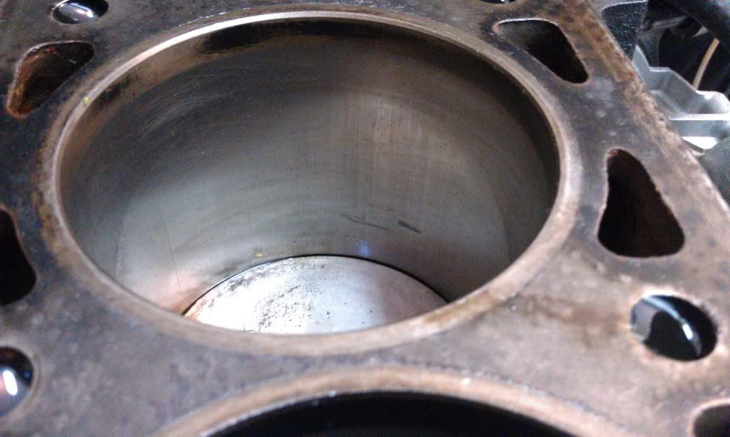
Here's a pic of the cylinder walls. When I rebuilt this motor in '99, my local machinist told me the block was OK to just re-hone so that I didn't have to buy new pistons (which was out of my budget at the time). It really wasn't OK. There was a slight ridge and some scoring back then that didn't come out with the hone job. He said it would be fine, and I didn't know any better at the time. Now they're just worn more, and ring gaps were over double what they should be (ring gaps were in spec at the bottom of the bore, over double the max at the top).
Member
Probably from that detonation you mentioned.
Your build is going to be exciting, for me too
Tbd
Member
It was on the cap side, so more likely due to the mechanical overrev..
Member
I was just thinking that. Possibly a brief lapse in oil pressure due to pump cavitation? Or can a crankshaft flex in that situation?
"The most important thing is balance." - KT
Member
all in all, kind of surprised how well this engine hung together knowing the small details.
Backwoods Libertarian
Contact the bearing manufacturer & see if they can tell you what caused that. I too noticed it was on the cap side.
"The water was not fit to drink. To make it palatable, we had to add whisky. By dilligent effort, I learnt to like it." Sir Winston Churchill
Member
I don't think an overev would even faze the crank's rotating mass, valve float would occur at an rpm long before the limit of the crank.
Tom D
77 e21 - m42
88 e30m3
04 330 dinan3
84 r1000rt
02 r1150rs
all of them gray
14 f800gsa - red headed stepchild!
Soulless Ginger
.
Member
Member
^ that's a great site, thanks.
Tom D
77 e21 - m42
88 e30m3
04 330 dinan3
84 r1000rt
02 r1150rs
all of them gray
14 f800gsa - red headed stepchild!
Member
Thanks for the pix- sorry to hear that the machinest's advice didn't pan out. I was curious about weather or not that moneyshift from a few years ago had anything to do with this as I remember that you thought that it ran differently afterwards, but it doesn't look like it from the pix.
The information on the hone job was a good lesson- double check the machine shops work! Plastigauge the crank and check end gaps of rings. All in all though, it seems to have lasted quite a long time, especially considering how hard you flogged it!
Member
cant wait to see how this thing turns out..
Member
Before I pull the plug and buy the parts, I want to decide on rings. This appears to be an uncommon ring size. Rings only come with the Wiseco pistons if purchased in a full set of 8. Obviously, I'll buy 4 individual pistons and I don't see Wiseco rings for sale anywhere separately. The only options I've found so far are the JE and Total seal rings (see first post).
The rings are 1x1.2x2.8 mm. This is a REALLY thin ring set to run on the street, particularly for boost. The thinner ring causes less drag and helps the top ring seal better at high rpm, however it also makes the ring weaker. From what I've read, rings this thin on a boost application are ideally made from steel rather than ductile iron for strength.
Most common top rings are made from a moly coated ductile iron. Moly can flake under the heat associated with boost, and ductile iron is less than ideal for boost, particularly on a ring this thin. The JE top ring is gas-nitrided (hardened) steel top ring (perfect), while the Total seal appears to be a basic ductile iron (not good).
While the idea of not needing to run larger ring gaps for the boost with a gapless top ring is appealing on a boosted motor, the T3583XX is a gapless 2nd ring set. This theory doesn't make sense to me. I think it would make the potential for pressure buildup between 1st and 2ng ring high, particularly on a turbo motor. This pressure buildup can cause top ring flutter and ring unseating at high RPM.
I'd rather run a gapless top ring and standard second ring since the top ring typically does a majority of the sealing and current ring theory suggests that 80-90% of what the second ring does is oil control. Many engine builders and some ring manufacturers including Speed Pro now recommend running larger second ring gaps to prevent pressure buildup between the top and 2nd rings. This theory suggests a total seal top and standard 2nd ring is ideal, however I have concern about a ductile iron ring this thin for boost. I'd have to contact Total seal directly as I can't find this part number (M3583XX) available for sale anywhere currently.
So, I'm currently leaning toward the JE, it's cheaper and made of higher quality, stronger materials and seems it will hold up to higher boost levels better.
Last edited by jrcook320; 09-12-2012 at 12:02 AM.
Backwoods Libertarian
I've never built a turbo engine, but from an engineering standpoint the JE rings sound like the prudent choice because of the stronger material especially with the width you're talking about and given you're going to crank the boost up on this one.
My only concern is how well they'll seat given that they're hardened and the kraut iron cylinder blocks seem to me to be harder than American. This I know from having done machining on both and having seen 150k+ mile m10 blocks that still have the original honing marks in the bores.
I'd definitely check with JE for compatibility and if any special cylinder wall finish is recommended.
"The water was not fit to drink. To make it palatable, we had to add whisky. By dilligent effort, I learnt to like it." Sir Winston Churchill
Member
It's time for an update. I only get a few hours a week to work on this thing, so progress has been slow.
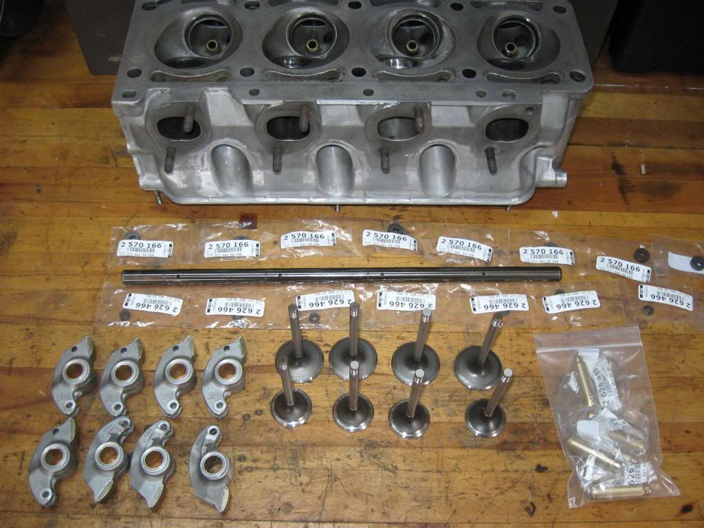
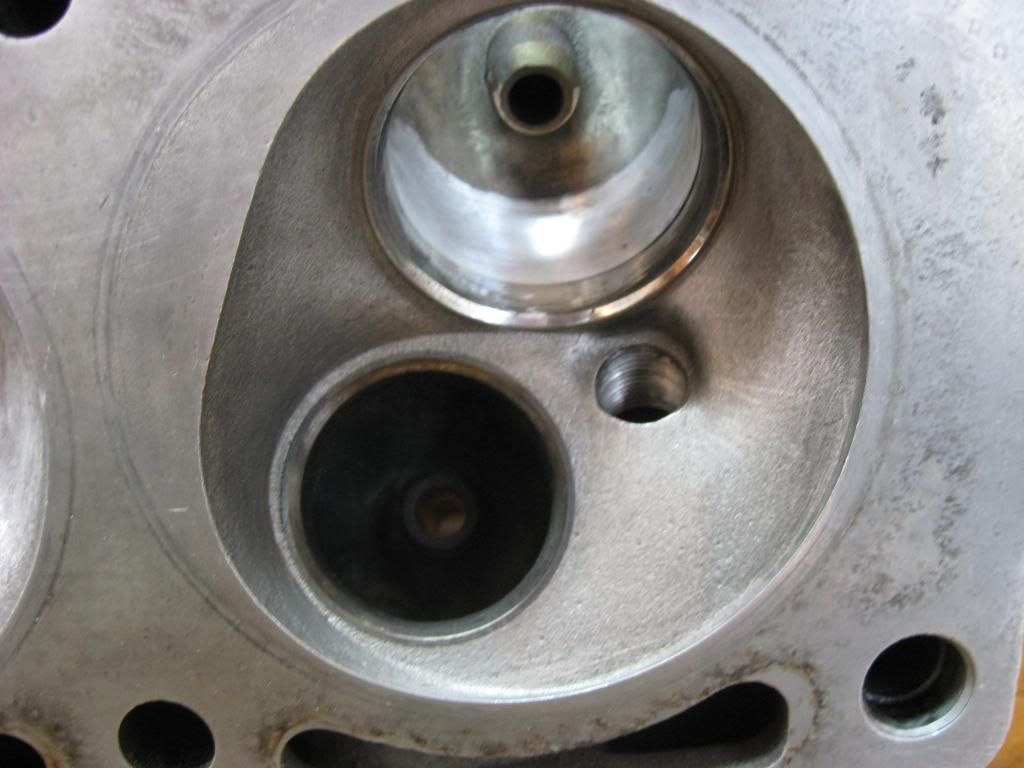
I decided to start with the head before spending any money on the bottom end. I tore the head down to to clean and inspect components and refresh anything worn, thinking it should be good to go. This was a "rebuilt" hi performance head from bavarian engine exchange, purchased 13 years ago, with only ~40,000 miles racked up since then. What I found was dissappointing.
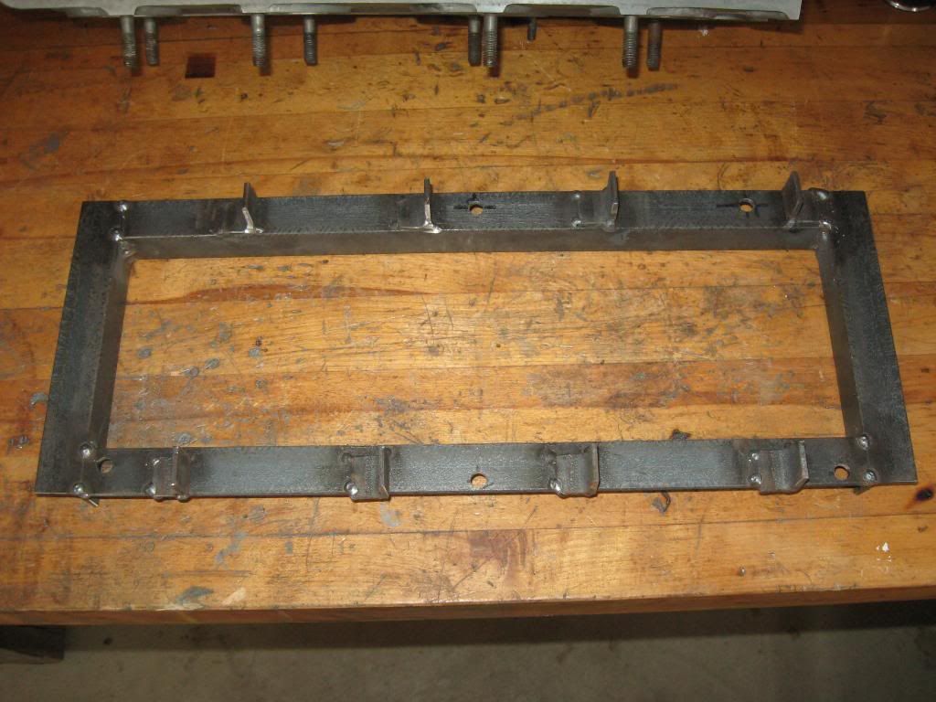
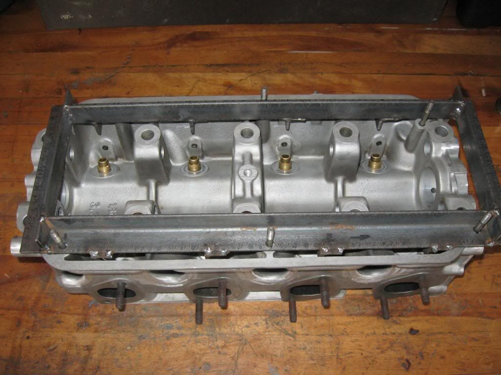
I made a cam removal tool out of 1 1/4" angle iron which happened to be a little too small for the job, but I made it work. 1 1/2" would have been ideal, I had to stack washers on the studs to get full rocker compression.
Once everything was clean I began measuring and inspecting.
Radial Valve Play:
I put a dial indicator on the valves just off the seat to try to estimate guide clearance and measured .25mm on the intake and .3mm on the exhaust. Maximum radial play is .025-.055mm on the intake and .04 to .07mm on the exhaust, so my guides need replaced.
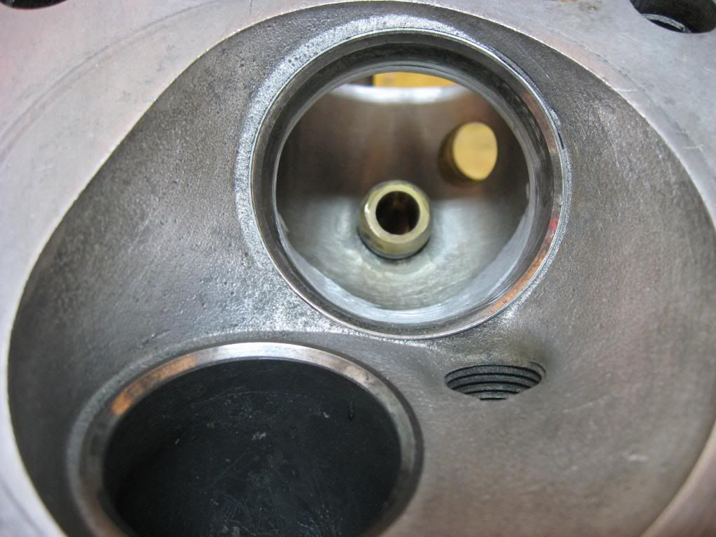
Valve stem diameter:
intake: spec: 8.0mm -.02 to -.04 (min. 7.96mm) - actual: 7.95mm
exhaust: spec 8.0mm -.04 to -.055 (min 7.945mm) - actual: 7.945
This is close enough to low limit I'm not going to bother running it, so I also need new valves.
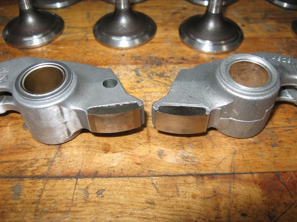
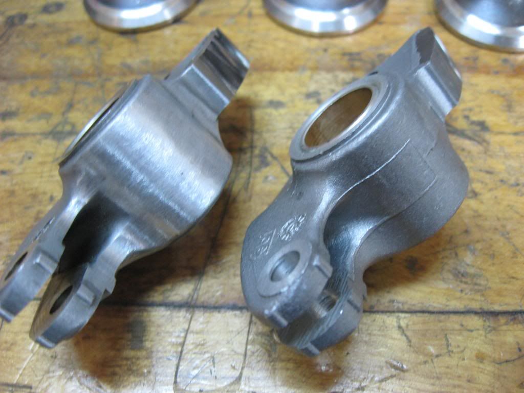
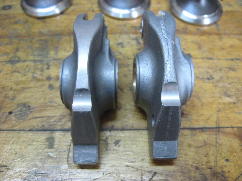
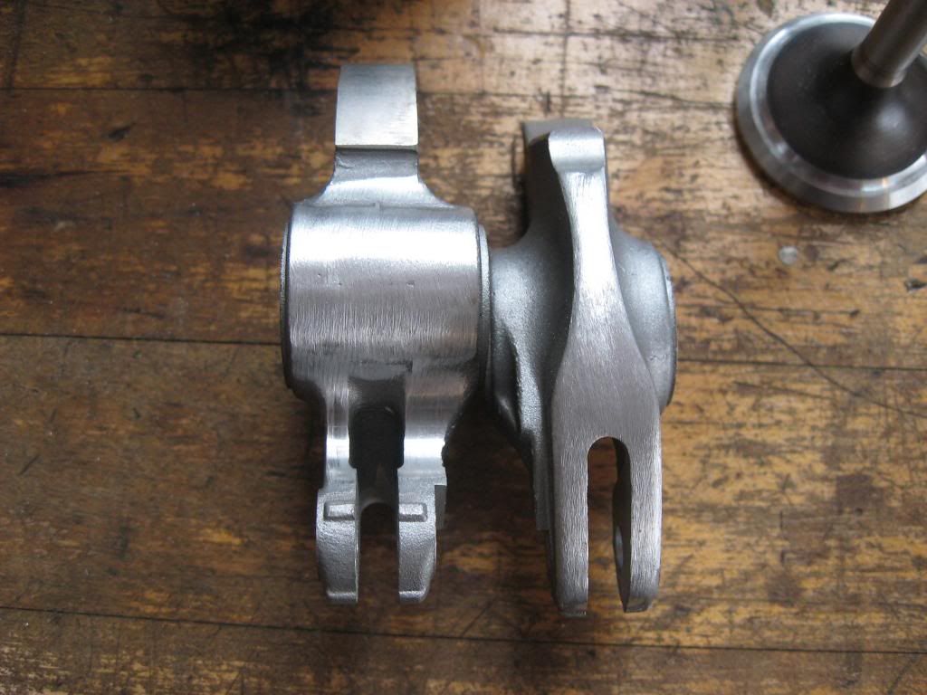
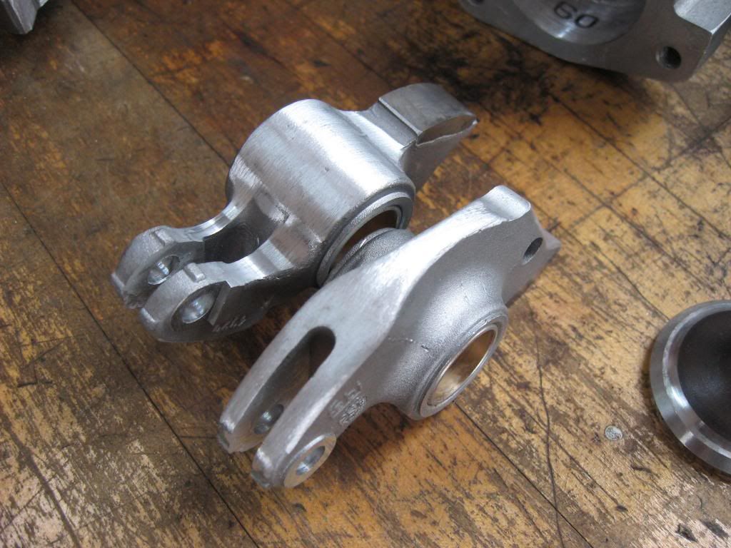
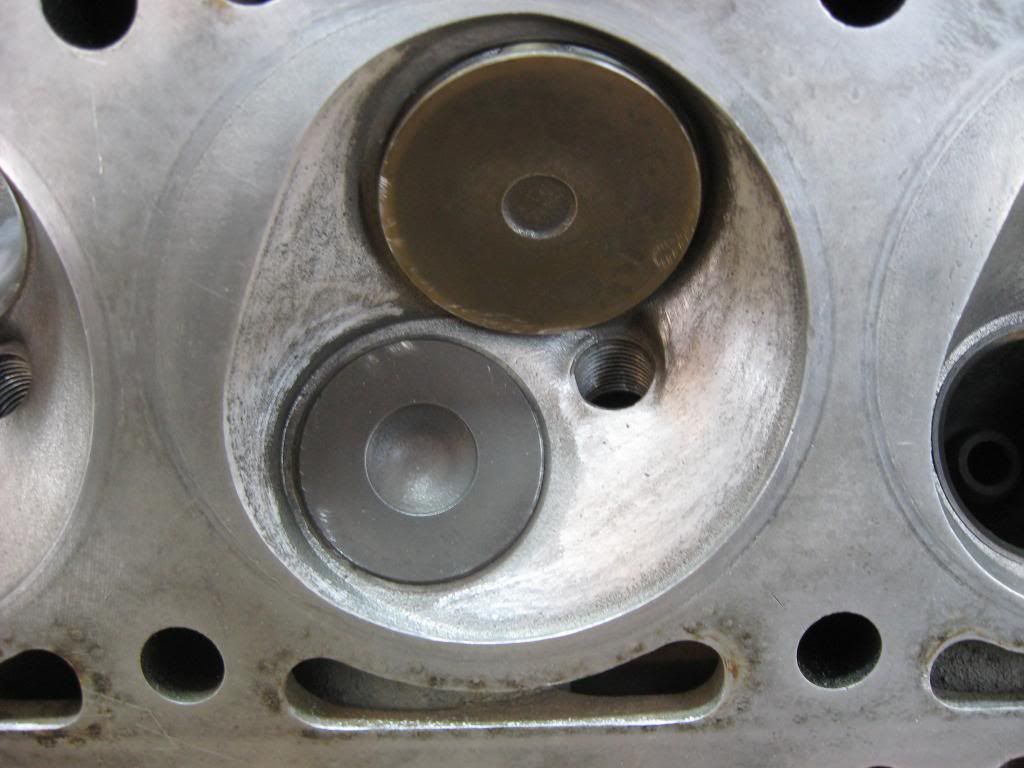
Rockers: All of the rockers have signs of wear on the cam follower pads, and the bushings were worn beyond maximum spec (old on left, new on right)
Rocker shafts: You can one is much more worn than the other, indicating at least one was worn when the head was assembled. Both are worn below minimum spec.
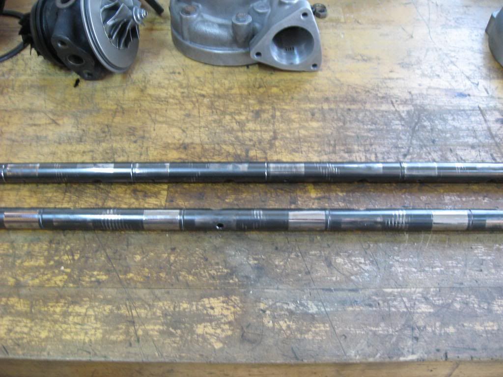
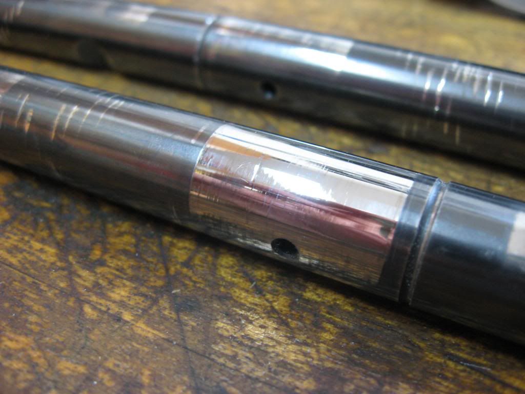
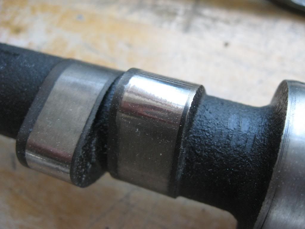
Camshaft: each lobe has some minor wear. Since I have to replace the rockers, I going to replace the cam anyway. On the rear bearing there are signs of previous damage and uneven wear.
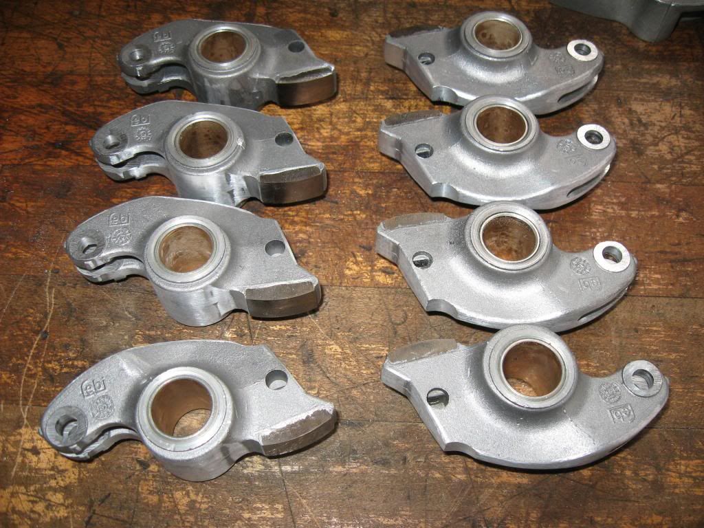
New Intervalves valves, Canyon guides, Febi rockers and eccentrics, and OEM rocker shafts:
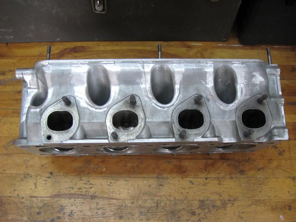
I removed the casting/parting lines on the rockers. I'll continue with polishing and may have the shot peened.
I also went around the head cleaning up casting imperfections. No real reason, other than because it was fun.
And, of course I'll clean up the port job. It's OK, but I'd like a better short side radius and smoother bowls. I also plan to clean up and smooth the chambers. I've only just begun in these photos.
Next up, cam shaft selection...
Last edited by jrcook320; 03-17-2013 at 10:01 PM.
Member
Go Josh Go
Member
Why?I removed the casting/parting lines on the rockers.
Is there a "real reason" to do this? Or was it just for fun (like on the head)?
Just curious...
==========================
"Somewhere the zebra is dancing."
==========================
banjo_84us@yahoo.com
It reduces the chance of developing a crack. Cracks always start from the sharpest edge or corner they can find.
Member
Wish I still had that crank. I will be watching this build and coming to see you for a ride when its done.
Member
Are you planning on welding up the water jacket on the head?
WOT
Member
Explain??
- - - Updated - - -
I wasn't planning on replacing the cam since I've been satisfied with it (both NA and turbo). Long ago I was able to get specs from bavarian engine exchange on the cam, I've long since lost them, and they've told me years ago their engine builder from that time is gone. It was 280 cam with about 9.2mm valve lift (IIRC, I'll be measuring to be sure). Once I have a baseline for lobe separation and lift from my current cam, I'll be able to make a better selection.
I think anything over 280 advertised will be a little too much for my combination, but I'm listing the 284's out of curiosity anyway. I want to go for max lift with a wider lobe separation angle. I often felt that I was blowing through the motor at full boost between 3000 and 3500 rpm where it would get wild.
Schrick lists the rocker ratio at 1.3, Elgin at 1.25, and Schneider at 1.26. I'll assume the correct ratio is 1.3, and valve lift info is calculated below with that assumption. I'll fill these in as I gather more data:
Stock Cam
Cam Lift | Valve Lift | duration | LSA | IO-IC-EO-EC
6.96 | 9.05 | 264 | 114 | 18-66-66-18 (note - these numbers are listed in the factory service manual with a 236 @ .020" lift and 4-52-52-4 valve timing. The valve timing is calculated based on the advertised 264 duration. The 114 deg LSA is calculated based on the valve timing specs, and conflicts with what cam grinders suggest the stock cam spec is)
Shrick 284 (VAC sells genuine, Ireland sells a copy)
Cam Lift | duration | LSA | IO-IC-EO-EC
7.2 | 284 | 110 | 32-72-72-72
7.6 | 292 | 110 | 36-76-76-36
Schneider Cams
Cam Lift | duration | LSA | IO-IC-EO-EC
7.25 | 272 | 108 | ?
7.25 | 284 | 108 | ?
turbo grind listed as available... emailed.
Elgin Cams
Cam Lift | duration | LSA | IO-IC-EO-EC
7.31 | 278 | ? | ?
8.23 | 284 | ? | ?
Turbo cam?
TEP - turbo grind
Cam Lift | duration | LSA | IO-IC-EO-EC
7.69/7.69 | 274/278 | 110 | 27-69-67-29
Any other options out there?
- - - Updated - - -
Any time... That would be awesome.
Last edited by jrcook320; 03-19-2013 at 07:49 PM.
Member
Best example, Look at post #27 of the following,
http://www.e30tech.com/forum/showthr...t=22030&page=3
The m10 combustion chamber is unsupported at the water jacket location, just like the m20. If I had to do it all again for high hp, I would weld the jackets, o-ring the block and run a stock HG.
WOT
banjo_84us@yahoo.com
Interesting. Never heard of that on an M10. Must not be totally necessary, as I've seen many high HP builds without it.
 Posting Permissions


 Reply With Quote
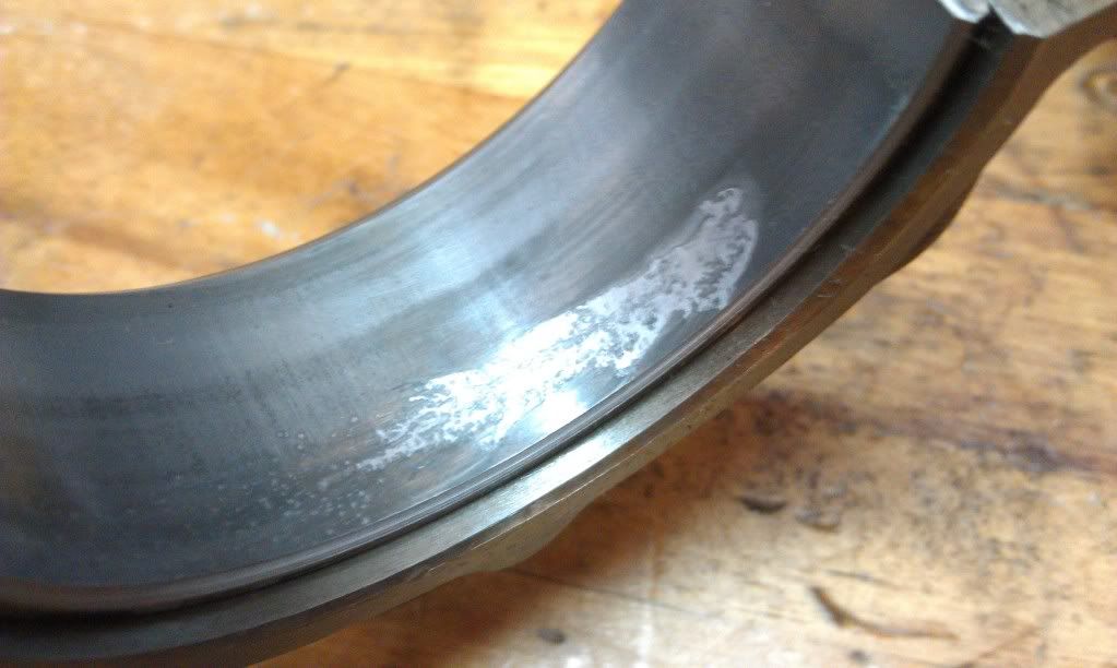


Bookmarks