
 I punch my coffee
Good afternoon everyone, I'm pleased to finally have my Pixel Repair completed and now with enough pictures that I think I can safely guide those of you who were slightly nervous about doing this repair. Initially I was very disappointed because I thought I had royally botched the job, but it turned out that I had inadvertently burnt out a couple bulbs so the LCD did not light up like it should have.
So, buy your kit from eBay, doesn't matter which one, just don't get the one with the absolutely unnecessary soldering iron tip. You'll notice I did not use a soldering iron at any time for this. And there is a reason for that. I use a soldering iron daily/weekly at work, I've been soldering for 23 years (For those that remember the how old are you thread, yes I am only 30, but I worked at the family business since I was 7 soldering, fixing circuitry, etc.) and guess what, this repair DOES NOT NEED ONE. Good idea those eBay sellers had trying to sell unnecessary stuff to us BMW owners since our pockets are so deep. Right?
Anyway, without further adieu!
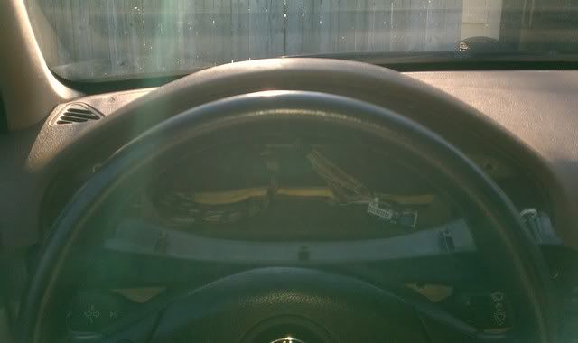
Step 1: Remove Gauge cluster. Sorry I have no pics of this procedure, I will add them later because I ordered a Gauge Ring set from DDM tuning so the cluster has to come ont one last time. A word of the best advice I can give you right here. Plug the headlight switch, the dimmer and the fog light switch back in after you have the cluster out. Or you'll be coming back outside to a dead battery when you're done with the repair as the lights go on when you unplug the headlight switch. OR you could disconnect the battery.
Step 2: Now we're ready to start disassembly. I think it would be best to state here that I used extensively this writeup by burnout187, (and I even borrowed a few pics from his DIY since some of my pics of the same stuff came out blurry) to disassemble, but I was left with a few questions so I decided to do my own in hopes I could help others with some of the same questions. http://www.m5board.com/vbulletin/e39...-pictures.html
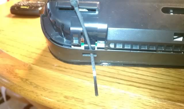
I used the zip tie method as well
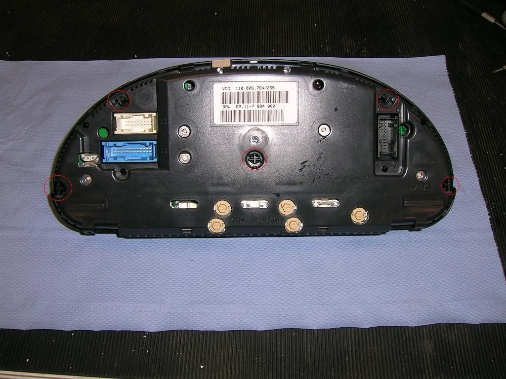
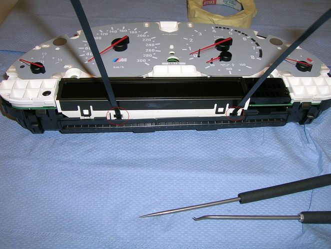
Step 3: Now that you have your zip ties inserted in the tabs to keep them open, you have to somehow grow like 5 extra sets of arms. You'll need needle nose pliers to grab onto these cross/x shaped posts and twist them slightly to line up with the unlocking holes all the while exerting pressure on the housings (prying them apart) until you get these cross/x shaped posts all "unlocked". Start in a corner and go one by one around the assembly. They're circled in Red here in this image from Burnout187
Last edited by Black540Msport; 12-07-2011 at 07:19 PM.
I punch my coffee
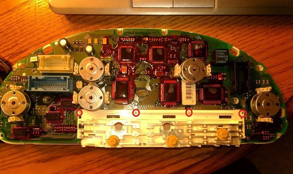
Step 4: Once you have gotten the 2 halves apart, you'll need to remove 8 Torx screws that hold the cluster to the back housing, they're circled in red. One thing you'll want to watch out for is the little square of plastic that shows what gear you're in, falling out. It's not held in at all. It's in the green square. Remove it and put it somewhere safe for reassembly.
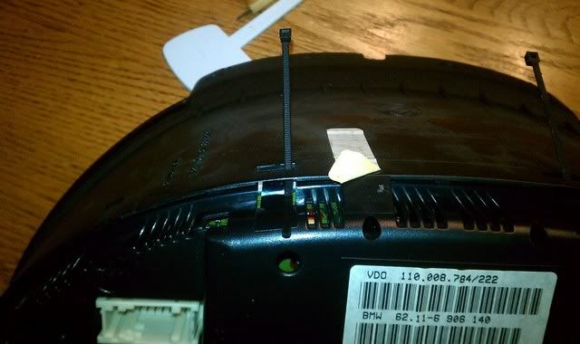
For this next part you'll likely need a dental pick or a long very flat but stout utensile to close up the clips on the 3 plugs on the back of the gauge cluster. The Blue, white and black plugs seen here are where the clips are located.
And here is what the clips look like so you can have a mechanical understanding of how they work. Look closely at the blue and white plugs here; the retainer clips need to be pushed in while, again, exerting pressure on the housing - pulling it and the gauge cluster apart. I found it easier to do the black plug first then pull apart as you sequentially push in the clips on the blue and white. The whole assembly should then pop apart. Don't forget to pop the clips under the LCD display with zip ties. See below image from Burnout187
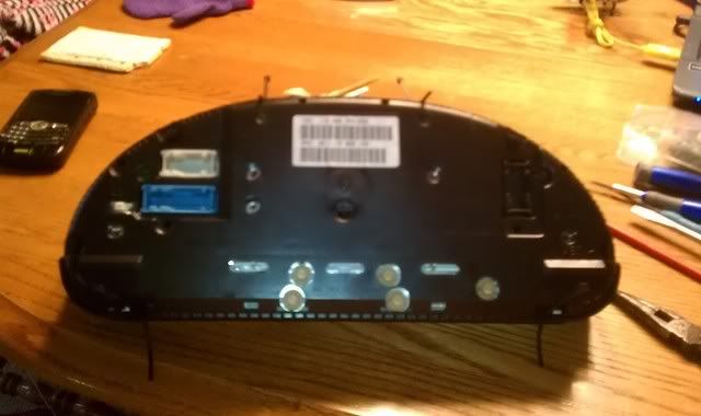
Step F: Now that we've removed the front lens and the rear housing, you're left with the cluster only. Seen here is our quarry, these 4 little Torx screws are what need to come out so you can install your ~$20 flex cable. But how do you get to them? From the other side of course!
Going from left to right these are the exact locations of the holes. Mark them with a permanent marker as you go. Use a drill bit no bigger than 1/4" to drill these holes, and in fact I think I used 3/16". And remember that the torx screws are only about 1/4" below the surface of the white plastic you're about to drill through.
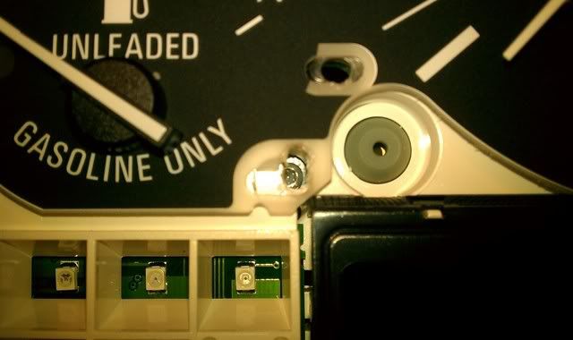
Note the exaxct location here, right on the edge of the clear plastic circle that has ridges in it, DIRECTLY below and offset 1/8" to the right of the "0" (10 mpg)
Self explanatory
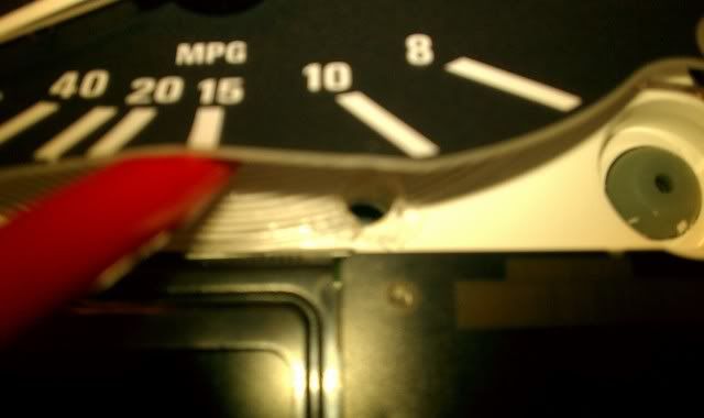
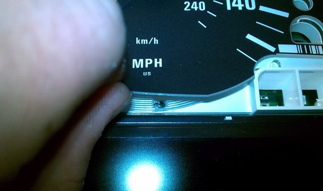
Lastly, this one is again, directly on the edge of the clear plastic circle piece with ridges in it. Located directly under the H in MPH
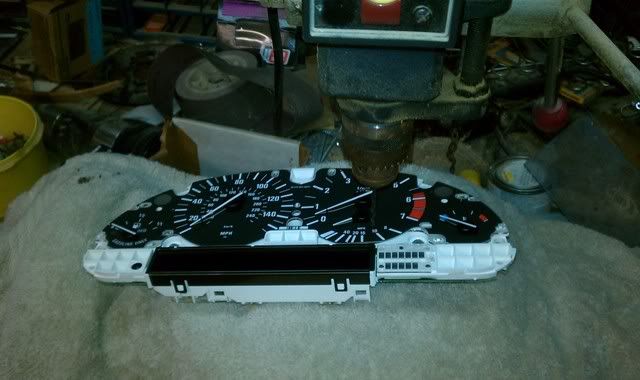
Step 7: I used a drill press with a towel on the metal table. I'm kinda conscious about static charges since I am supposed to work on an anti-static bench at work with a wrist strap and everything. MAKE SURE THAT YOU LIFT UP ON THE PLASTIC OVERLAY BEFORE YOU DRILL YOUR HOLES UNDER THE SPEEDOMETER AND TACH, DO NOT DRILL THROUGH IT!
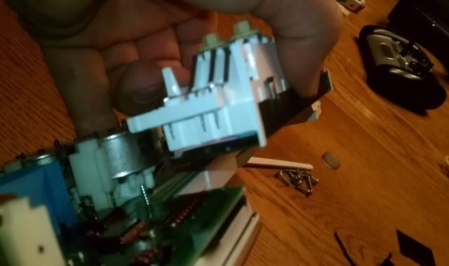
I drilled my holes and unscrewed the torx screws. You'll need a small flat blade screw driver to pry apart the white LCD housing from the circuit board. It's better to use a plastic non-marring tool if you have one but just be careful not to exert too much pressure as you can crack the circuit board or slip and knock off some resistors or cut a trace that goes to an integrated circuit.
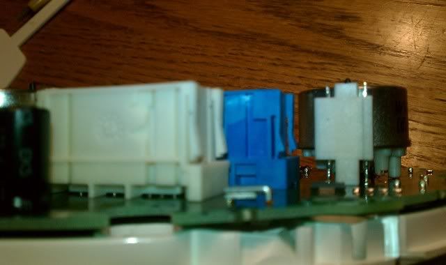
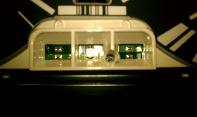
This is your reward after you've unscrewed everything and pried the LCD off the board, you'll notice that there are 3 metal legs that you need to be careful not to bend, that can be seen in the picture. They're what goes through the circuit board and supplies power to the backlights for the LCD readout.
Now you can separate the old flex cable from the LCD and the main circuit board. Just pull, it'll leave behind residue that needs to be cleaned off. I found that my plastic non-marring tool worked great on the LCD side seen here. DO NOT USE ANYTHING OTHER THAN PLASTIC ON THE LCD TO SCRAPE THE RESIDUE OFF!
On the circuit board side I scraped for what felt like forever to get the traces cleaned off, then I grabbed some ~600 grit emery paper and did a light pass to ensure all traces of the gunk from the old cable was gone. AGAIN, DO NOT SAND THE LCD WITH EMERY PAPER, ONLY THE CIRCUIT BOARD'S TRACES ARE TOUCHED WITH THE EMERY PAPER!
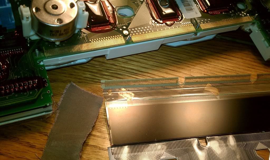
Here you can see that after scraping the gunk off with my plastic tool and then lightly rubbing the traces with the pictured emery paper, all traces on the circuit board look pristine.
Also notice the new flex cable at bottom, and the old one still attached to the LCD, you can see what was left behind on the circuit board, the broken traces are what caused the pixel readout to not work.
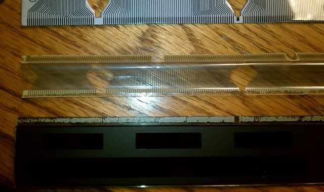
Another picture of the original cable and the new cable with the LCD
Step 8: Grab the scotch tape!
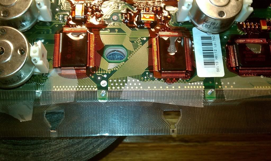
Here I just cut some mangled pieces of tape and used them to secure the cable to the board. It is absolutely IMPERITIVE that you get the traces on the circuit board lined up with the ones on the cable. I believe I peeled the cable off a few times before I got it perfect. One thing to note. DO NOT press down on the cable, just tape it to the circuit board for now, don't rub it to try to get a wrinkle out. Peel and restick.
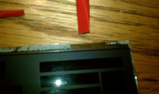
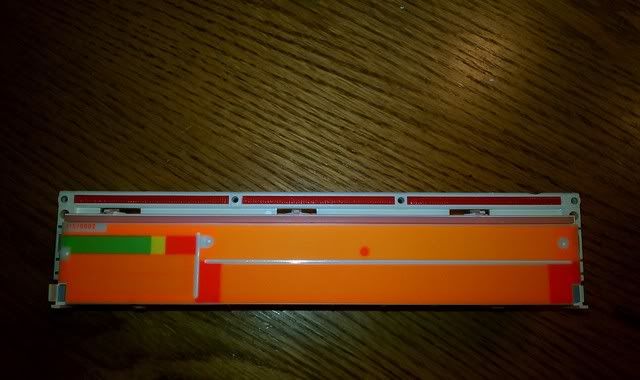
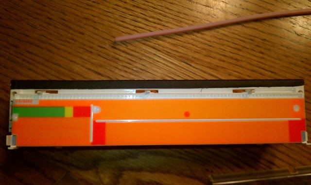
Now we need to attend to the whole stupid reason you're doing this in the first place. That white housing. Notice here the 3 Red sections and the single long pink section of silicone gel. Yah, those are why you're doing this. I reasoned though, that only the red ones were causing the issue.
So to remedy the issue I used some heavy cloth tape called Gaffer's tape. This will add enough height to the area where the flex cable is sandwiched between the white housing and the circuit board. You do not need to increase the height of the pink silicone strip in my opinon. You run the risk of cracking the LCD when you reclip the cover over the LCD.
Well, now you're almost done. All you need to do is reattach the LCD assembly to the flex cable with some scotch tape, take your time, and get it lined up perfectly. Screw down the assembly snug (don't overtighten or you'll crack the plastic holes!) once you have it all clipped back together and test the unit. The BEST piece of advice I can give you right here is do NOT reassemble the whole unit. Just take the cluster only out to the car and plug 'er in. Make sure your fingers are not touching the circuitry, and the circuit board isn't resting on the round metal bar inside the dash, and turn the key.
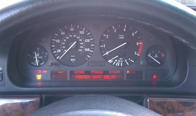
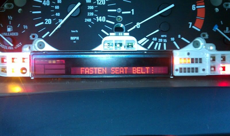
Hopefully you see something like this
If you're successful and you can now read your message center, go ahead and clip everything back together and reinstall the cluster pod in the dash.
I got mine done in only a few hours. It probably took me as long to put together this writeup as it did to do the repair. And it only cost me about $20!
Now I get to look at this when I get in the car, before I had NO idea what the message center was telling me haha
Last edited by Black540Msport; 02-15-2014 at 09:44 PM. Reason: Automerged Doublepost
BMWCCA Member
Damn, you are brave.
2001 540 M-Sport (cdn), ST X (KW) coilovers, H&R 15mm spacers, Eibach anti roll bars (28mm/18mm), Beastpower rear antiroll bar brackets, M5 rear chassis reinforcements (traction rods), Strong Strut front upper strut bar, Dinan Stage 1 software, factory M-Audio subs, Bavsound speaker upgrade, Bluebus bluetooth integration, Stop Tech SS brake lines, ATE coated brake rotors, ATE ceramic brake pads.
I punch my coffee
I am also Dutch and I have worked around electronics for 23 years. So the cheap-skate in me makes me do DIY stuff, and the electronics background makes me not scared of these kinds of things.
Member
Damn, nice work!
How long does it take and when can I stop by so you could fix mine, I'm ~195 miles away
2018 Genesis G80 Sport 3.3T AWD Havana Red
2015 Hyundai Genesis 5.0 V8 (sold)
2013 Hyundai Genesis 5.0 V8 R-Spec (sold)
1999 540i/6 (sold)
Member
Great info. Will be giving this a go at some point. Thanks.
I punch my coffee
Haha, it took me about 2 hours when I did it the first time. And stop by whenever.
Member
PM'ed youOriginally Posted by Black540Msport

Thanks,
Darek
2018 Genesis G80 Sport 3.3T AWD Havana Red
2015 Hyundai Genesis 5.0 V8 (sold)
2013 Hyundai Genesis 5.0 V8 R-Spec (sold)
1999 540i/6 (sold)
Member
i gotta do the MID repair as my winter project. your DIY on the cluster really gave me confidence to jump head first into the MID(which is easier fix)
2001 540i 6speed metallic silver
BMWCCA 484984
Posts # 2 and 3 quote before deletion. I want to keep the OP's two posts together.
BTW, excellent job, Brad.
Last edited by jamesdc4; 12-07-2011 at 09:08 PM.
Member
The only scary thing is you gotta drill the holes. I will live without some pixels for now.
Member
AWESOME writeup!! If I ever have to accomplish this I'll be glad for your work.
If I can make one small suggestion? Edit your original post and throw a carriage return every 20-25 words or so?
That'll make so people don't have to scroll side-to-side to read things.
Thanks again!
Member
I really need to do this and I will probably tackle it over the Christmas holiday.
do you happen to have a link to the strip that I need to buy? Don't want to get the wrong one.
Awesome write-up btw!
Edit- I bought the ribbon!!! I ended up going with the slightly more expensive one from the recommendation in the m5 board write up as it supposedly comes with a 10 page instruction manual and a great video instruction.
Hope I don't screw the whole thing up!! LOL!
Last edited by dcroghan; 12-08-2011 at 12:11 PM.
Dinan CAI | Dinan MAF | Dinan Exhaust | Dinan Stage 4 Engine Software | 19" Staggered M Par Reps | Rear Lip Spoiler |
Member
Hey. Im also dutch. If ur not to far away i would like to see if u can do mine.
BMWCCA 484984
The scrolling is caused by the addition of a large, high-res photo.
Member
I know. Fixing the scrolling could be done by shrinking the pic or putting in CRs every so often. Since the large pics add to the understanding over what a smaller one might, I recommended the CRs...
Member
Yep, exactly what I did too. The worst part was getting the new cable to line up and make good contact. I think you are supposed to use a special heating gun/station to attach the ribbon to the glass but this method of using tape sometimes works as well
Also, talking to the guy that fixes these there are crappy/cheap cables on ebay and not all are of the same quality. just an fyi
Good work!
Last edited by 84318i; 12-08-2011 at 12:03 PM.
e30 84 340i m6x powered.
e34 89 535i 5speed - current DD
e24 89 635csi - maybe a DD?
e34 93 525i (m50tu) - gone
e39 540i 6spd m-sport - gone
e53 x5 4.4l - gone
e30 89 325i (m20) - gone
Member
You Da Man!
Member
thanks for this diy... i will be doing this soon, unfortunately
I punch my coffee
Where are you located? I think I have Dareck coming up from Chicago next weekend to do his.
Last edited by Black540Msport; 12-11-2011 at 01:52 PM.
Status Quo!
Outstanding work. Kudos!
Another FP5241 Creation
Parting out M54 Engine. Intake and all. Cats avail as well. PM ME!
Member
Black540Msport,
You are a brave man & like many others have said excellent work & write-up...
I punch my coffee
Thank you everyone. I will probably go back over this with a fine toothed comb and update things where I see fit/necessary. I'd like to even include short videos of some of the tougher things like getting those stupid cross/x posts undone. We'll see where this goes. Hopefully it gets added to the DIY sticky.
Banned
You could make money providing this service to others. Please consider if you are willing to provide this service. If so, please PM me or post so we can discuss the details.
Member
Great write-up, i ordered my cable tonight. One question though: is cellophane tape really adequate for attaching the ribbon? After time i've noticed that the glue can break down. Is there a certain product you prefer, like 3M maybe?
 Posting Permissions


 Reply With Quote
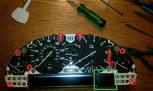


Bookmarks