
 Member
djcristi, is this a FT232BM you're using?Originally Posted by djcristi

If yes, I think you installed the transistor backward. On yours, the emitter is going to pin 20 which is DSR and the collector is going to ground. It should be the inverse.
I would be carefull with the use of a very high value resistor at the base. If there is not enough current going into the transistor base, it may not be switched ON 100%. We are using the transistor as a switch and it should work in saturation.
Hi poteroa,
while looking at the mods for the cable, I found a little mistake in one of your pictures that may induce some people in error.
In the second one, it shows the TO-92 with the labelling EBC. Since the transistor in the picture has its flat side down, it should read CBE.
Last edited by TurboBimmer; 12-15-2010 at 10:33 PM. Reason: Automerged Doublepost
Member
Hi.
I took the the picture from manufacturers page that has the info of the transistor. Check again, no mistake, the pinout is quite right. the C-leg is suppose to go to RL_chip pin 9, and yes the transistor in the picture is facing down.
Last edited by poteroa; 12-21-2010 at 12:58 PM.
Member
Hi guys i found some old video tutorials that i made sometime ago, about software configuration (ediabas,inpa and dis) but they are in spanish language.
Anyways maybe you will find them usefull
here we go
Advice: i remember there's one step missing in ediabas and something else that i can't remember but DIS configuration is ok lol
1º Set environment variables
2º Installation of bmw-tools (ediabas)
3º Installation and configuration of the USB port
4º Installation and configuration of INPA
5º EasyDIS and VM Ware installation
6º DIS v44 installation
7º Final configuration of DIS
Member
Hi,
Do I have to modify something in the 20PIN/OBD2 adaptor to make ignition detection work ?
DIS says the 15 pin is OFF when I try to scan the car, it does not detect battery... any idea ?
Thank you
Member
up
Member
i have a question is this cable mod as good as a gt1 cable or whats the differences between this two cables. and are there any update on the d-can cable, is it possible to mod the vag cable to handle d-can?
Member
Could someone make me a modified version of this one ?
I cannot manage to this so small soldering
of course i pay all costs?
Member
Hi Locum! Id like to thank you for sharing your knowledge with us. Thanks to you I have a perfect working OBD adapter
Heres something interesting...
Id would like to update the flash eprom of my radio module (BM54). Ive have read (xoutpost.com) that it would be possible without desoldering the flash eprom.
Therefor I would need an USB <-> Serial (TTL) adapter. Question is... what kind of signal are K and L line? Are they TTL signals? Can I (ab)use my VAGCom adapter as an USB <-> Serial adapter (must be TTL)?
Thanks
Member
You need to see:
FT232 Datasheet
Vagcom 409.1 Pinout
also you can use GOOGLE
http://rdist.root.org/2008/10/29/diy...serial-adapter
http://www.dhgate.com/usb-2-0-to-ttl...54e283240.html
Member
Hello,
I have bought this cable with FT232RL chip: http://www.obd2-shop.eu/diagnoseinte...rat-p-151.html .
Which looks exactly the same as poteroa cable.
Just 2 quick questions:
Will i be able to program car key memory with only the software mod (with SSS/progman)?
If this is true i won't bother the soldering part.
I have modified poteroa picture to this one:
Is this correct??
Thnks
Last edited by Egbert87; 03-22-2011 at 12:33 PM.
Member
Hi all,
I went to Radio Shack and try to find the transistor BC546 but I couldn't find any. I bought a Radio Shack brand one that said 2N3904. Would this work in place of the BC546? Here's the rating on the package:
hfe(min): 100
Vcbo: 60V
Vceo: 40V
Vebo: 6V
Ic: 200mA
Ft: 300MHz
Dissipation: 350mW
It's a TO-92 case
Member
Hi, if you don't do the hardware you can't do car key memory with DIS... but you can do car key memory with NCS-Expert just soldering obd2 pin 7 and 8 and doing the software trick
Basically any NPN transistor will work.
Member
My modified VAG-COM KKL USB cable with Radio Shock 2N3904 is fully functional. You will have no problem using it. Cheap and readily available.
Fast lookin' but slow movin'
237 rwhp N/A power
Member
Thanks guys. I will try it out.
Member
PM me if you want to buy one of these modified cables. There is a new listing on ebay for BMW kkl cables though...
Last edited by AdrianEvans; 03-31-2011 at 05:44 AM.
Member
This is NOT ebay
Member
So this should work with carsoft 6.5?
INPA is working great but I can't get carsoft to connect to any of the modules. Any tips?
Thinking about adding some ceramic caps to the data lines...
Member
It won't work with Carsoft 6.5 but do work with Carsoft 6.1.4
Member
Good to know! will stop trying to get 6.5 working =)
moving on to SSS and all the other goodies
Member
Sorry if you take offence. Notease above asked and since I can not PM directly I made a post. Just trying to help a brother out.
Member
Nice thread for newcomer
Member
[QUOTE=Egbert87;21620992]Hello,
I have bought this cable with FT232RL chip: http://www.obd2-shop.eu/diagnoseinte...rat-p-151.html .
Which looks exactly the same as poteroa cable.
Just 2 quick questions:
Will i be able to program car key memory with only the software mod (with SSS/progman)?
If this is true i won't bother the soldering part
I have modified poteroa picture to this one:
Is this corre
is this cable the good one?
Member
[quote=theo318i;21745014]You have 2 options to modify CAR KEY MEMORY:
1. With DIS you need ignition detect (Easy use)
2. With NCS you don't need it (Hard level software)
BTW i didn't see your picture
Member
Hello everyone.
I have FT232BL chip. Should I solder 17,18 and 20 pins of the FTDI chip?
Thanks in advance
Last edited by zekan23; 05-06-2011 at 03:53 AM.
Member
1) First of all I should solder OBD2 pins 7 and 8, which are the K lines, otherwise I will not be able to access to all modules from the car.
2) After that I should do real ignition and battery detection as described djcristi at post nr. 21 using this scheme.
I need
1 resistance of 10 kohm or higher (djcristi used 120 kohm)
1 transistor BC546 or equivalent
Should I solder pins 17 and 18 of chip? Next photo is unclear, but on previous scheme they are soldered as I understood.
3) Downloading the latest driver v2.08.14 (release date 2011-04-12) from FTDI website and installing them
http://www.ftdichip.com/Drivers/CDM/CDM20814_Setup.exe
in My Computer settings set COM1 port and 1 ms of latency
4) Using Mprog 3.5 (was replaced by FT_Prog_v1.12)
MProg 3.5 http://www.ftdichip.com/Support/Utilities/MProg3.5.zip
or
FT_Prog 1.12 http://www.ftdichip.com/Support/Util...Prog_v1.12.zip
should flash the chip with the following
is it correct ???????
Last edited by zekan23; 05-06-2011 at 12:06 PM.
 Posting Permissions


 Reply With Quote
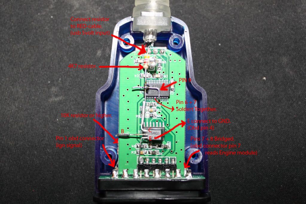


Bookmarks