
 Having No Trouble Here
BMW CCA Member
Having No Trouble Here
BMW CCA Member
Yo brosephine - you readin then aint too good.Originally Posted by yoice2005

- See my old thread which was linked just above. http://forums.bimmerforums.com/forum...8&postcount=77
- Also search for other threads. There's tons of pics of how this is done.
- Be sure you bridge the 7&8 too - seems guys loose sight of that when they are all caught up in the more technical stuff of putting a transistor in.
- Read some of the other threads / posts (I have made several) about versions of cables - some are easier than others and some are better quality than others. Quality doesn't matter for function - they all can work - but the worse versions have sh!tty PCBs that are hard to solder and components can come loose as you are modding and drive you nuts.
Good luck... .
2003 M3CicM6 TiAg
2002 540iT Sport Vortech S/C 6MT LSD TiAg
2008 Audi A3 2.0T DSG (the daily beater)
2014 BMW X1 xDrive28i (wifemobile)
Former:
1985 MB Euro graymarket 300SL
1995.5 Audi S6 Avant (utility/winter billetturbobattlewagen)


Member
I did read this thread entirely, more or less.
Now I am not sure what resistor value should I put as in the old post was saying about 2 resistors:
"but if we want some REAL battery and ingnition detect, we must do this circuit
1 resistance of 4.7 kohm
1 resistance of 10 kohm
1 transistor BC546 "
In your post, you used 300k which is much bigger than what it was initial suggested.
Thanks for being patient!
Catalin
Last edited by yoice2005; 02-18-2013 at 08:53 AM.
Having No Trouble Here
BMW CCA Member
Thanks for reminding me to be patient. (no jk - been a little interwebz testy lately).
If you read the thread link below you'll note only one resistor is necessary. The schematic is confusing (even more so if you can't read schematics!) because he's showing the internal pullup resistor which you DO NOT INSTALL because it is there already inside the component...
But note you want to bump up the 10k resistor to 100k-120k or something like that and then just a simple NPN small-signal transistor.
One more piece of advice: Tip - If the info here already isn't enough - then you're probably over your head. I do electronics for lots of other stuff so this is easy for me but if this is still confusing and over your head though, seriously, just buy a pre-made BMW cable from eBAY or get somebody else to do it. Unless you desperately want to learn soldering and electronics, it can be a little PITA and I've seen so many guys come in here and struggle and ruin cables and come back over and over begging for more help etc. etc.
I bought a Chinese KKL & D-Can compatible cable on eBay a couple months ago for something like $12. No hassles, seems to work for everything (although you have to run a software reconfig to go between D-CAN and KKL...) no worries. Works on my old mans E90 and my E46 & E39. No soldering no drama. Like I said I do this stuff all the time (I'm repairing a pile of Audi ECU's as we speak) but for 90% of guys what they really want is to get on with some fun coding and playing w the software. If so - just go eBay.
http://forums.bimmerforums.com/forum...4&postcount=21
Nope I use 100k and the explanation is in djcristi's post I just linked...
Last edited by geargrinder; 02-18-2013 at 09:04 AM. Reason: Automerged Doublepost
2003 M3CicM6 TiAg
2002 540iT Sport Vortech S/C 6MT LSD TiAg
2008 Audi A3 2.0T DSG (the daily beater)
2014 BMW X1 xDrive28i (wifemobile)
Former:
1985 MB Euro graymarket 300SL
1995.5 Audi S6 Avant (utility/winter billetturbobattlewagen)
Member
Thanks for all explanations! I have a background in electronicsMore I am an engineer (finished computers and automatics), but just don't have time to read all datasheets (working 9-10 hours per day in front of a laptop). And if smbd did it already, why not to appreciate his merit and practice what he "discovered".
I am doing this because I like it
Greetings from Bucharest!
Having No Trouble Here
BMW CCA Member
ha! i have been working with a Romanian colleague all last week - I think he's off to Bucharest in a few weeks for a work trip.
Sounds like you won't have an issue then.
Just one 100-120k resistor, value doesn't matter that much - 150k would prob work too. And then one NPN transistor - neither does the specific NPN transistor matter much. Notice in my post I didn't use that BD part number, I just grabbed some small signals from my junk box and have made a number of cables that work great.
But note the other tips above - some cables are easier than others to do. And if you haven't bought the Chinese cable yet you might as well buy one that is BMW compatible anyway...
2003 M3CicM6 TiAg
2002 540iT Sport Vortech S/C 6MT LSD TiAg
2008 Audi A3 2.0T DSG (the daily beater)
2014 BMW X1 xDrive28i (wifemobile)
Former:
1985 MB Euro graymarket 300SL
1995.5 Audi S6 Avant (utility/winter billetturbobattlewagen)
Member
I got a cable from a Romanian guy that seems to import Chinese ones. It is a black cable where pin 7 and 8 are already soldered. The cable works in INPA, DIS v57, SSS Progman after I invert from software the pins for ignition and battery. It is just not nice to have the 2 pins always on, and maybe when I will try more "fancy" programming I will get into issues as the feedback from the car is not 100% true.
I bought the BD transistor, 2 restors 4.7k and 10k already. I will go this week and buy a bigger one, but before that I will have a look on the datasheet as maybe the ones I have are sufficient
Member
can the modified vag-com interface now be usend in bmw AND vw(seat, audi,...)?
Member
Great job OP. This is crazy. How did you even figure something like this out?
Member
I read the majority of this thread, i have a 1999 e39 that i would like to code, i bought a cable that was for a serial port, is it possible to splice in the wires from an old usb cord and make this work? from what i understand all usb's use 4 wires, but my serial cord and my chip are wired with 6 wires???
also my circut board on my cable looks nothing like the other ones posted, so i may not even be able to modify this one to work. I dont believe it has the FT232RL chip in it.
any help would be greatly appreciated, i will update with pics in a second...
Last edited by rancor; 05-10-2013 at 07:46 PM.
Member
I'm assuming you don't have an actual serial port on your pc ?
If you don't, then you're better off buying the USB version of the cable. (blue vagcom cable)
Member
no serial port, but i would like to know if it is possible to salvage this, i dont mind spending the extra to get a vagcom usb cable, i just hate waiting for it to ship
Sent from my dungeon using a rock
Member
Hi,
I was wondering if you had more views of the set up so I can do it as well.
Tony
Member
Hi, I did this mod with S9013 npn transistor. INPA still shows two white circles next to BATTERY and IGNITION. And INPA still works even when these show OFF state. How do I make it so that INPA stops working until it detects an ON state? Also 2nd question is, is the #DSR pin 20 supposed to connect to anything on the board? During soldering the leg broke in half and pin 20 just floats in the air and I connected that to the collector of the transistor.
- - - Updated - - -
My previous post probably didn't make sense to most of you. I will try to explain it.
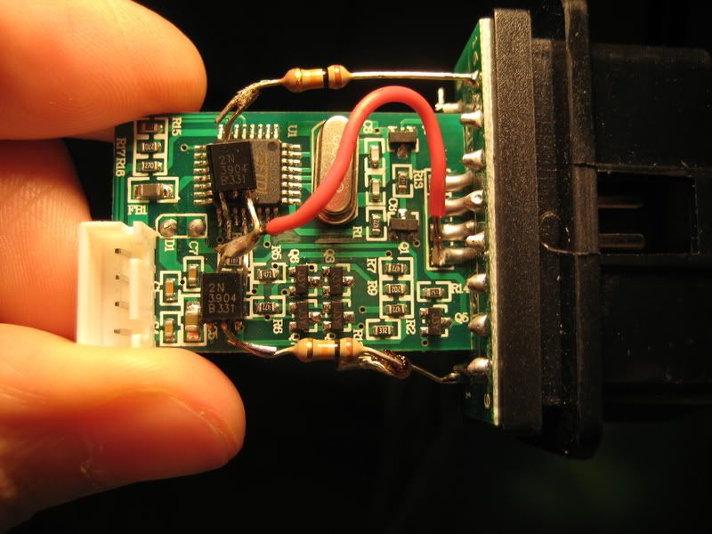
Apparently I thought the two white circles/black filled circles was a software setting, but it is in fact a hardware setting. Previously, when modding the VagCom cable the other end of the resistor is connected to the IGNITION pin 1. As in the photo: 2013-05-31 19.44.37.jpg
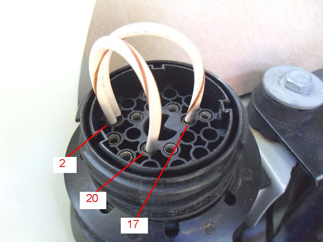
However, I found out that there is no voltage on IGNITION pin 1 where the resistor is connected, regardless if the ignition is on or not. So I thought, it might not be connected to the car at all. I opened up the a OBD16 to OBD20 round adapter:
2013-05-31 21.11.55.jpg
and then I realize that the OBD20 pin 16 is not connected to any wires in the adapter! According to this mapOBD20 pin 16 is the ignition signal and it should be connected to OBD16 pin 1. This is the idea behind the original mod. But there is no point if OBD20 pin 16 is missing. So from the same map I traced the 12V Battery signal from OBD20 pin 14 to OBD16 pin 16. I then connected the resistor in the mod to pin 16 instead of pin 1.
With this change, I'm able to see two black dots in the home page of INPA. Success!
However, I'm contemplating changing in the OBD20-OBD16 adapter by moving the wire from pin 14 to pin 16. Then in theory I should be able to see the black circles go white when I turn off the ignition and vice versa. (1) Do you guys foresee any problems by modifying the wire placement in the adapter?
Secondly, I realize that I can't read many modules with USB-OBD cable. I suppose I need an ADS adapter to read my E36 M52B20. I got this adapter, it is working with CARSOFT6.5, but I want to use INPA and DIS. (2) Is this an ADS adapter? (3) Can it work with INPA/DIS?
2013-05-31 21.02.08.jpg
Thanks for your time.
Member
The problem is with the adaptor, there is a sensible mod posted elsewhere on this forum that involve adding an additional wire to the adaptor to connect OBD pin 1 to BMW Round pin 16, which is the correct way to achieve what you want to do.
The cable you have is just a harness, it is not an ADS convertor, just a simple adaptor that allows you to connect to either a 16 pin OBD port or a BMW 20 pin round diagnostic port.
You will never get full ADS functionality with this interface and your car, but you may be able to read some modules (maybe the DME).
Member
Only because I couldn't fathom how INPA was "working" at all if the circles were white.
And you are correct, they indicate hardware connections with power.
Very common problem with some of the cheaper 20 pin harness adapters. Why they even sell them that way is stupid and annoying because you never know if you'll get one wired right. But you caught on to it.
If you completely remove the wire from pin 14 you will lose the constant battery signal. So while you will have a functional Ignition "dot", you will lose the Battery "dot".
Two seperate functions needs two seperate power sources in order to work independently as intended.
In your 20 pin adapter harness you need a wire from it's pin 16 (in the round end) to pin 1 on the OBD side. - "Ignition"
Leave the wire going from pin 14 (in the round end) to pin 16 on the OBD side. - "Battery"
Sometimes there is a green wire in the 20 pin harness that has been cut, if yours has it you could utilize it and fix the ignition line properly, but you'll have to carefully cut open the OBD end in order to do it.
It's not a standalone ADS Interface for sure. It shows to have an L-Line....so it MIGHT work. Best bet is to just try it.
From other readings it eems like the Carsoft interfaces are a bit finicky, but I've never messed with one.
Member
Thanks for replying nicely! I just realized now that I have figured out what was wrong (the missing connection pin 16 in the OBD round harness), I searched around the web and found so many posts about this already, which I didn't find before because I don't know the proper search terms. I'm sure it gets annoying to see people ask this all the time.
I also know what you meant by the "cut green wire" from those search results but I don't have it in mine. To link Pin 16 to the OBD2 port I'd have to make an external wire and I don't think I want to do that. How do you feel about me just shorting pin 16 and pin 14 in the OBD harness? Will that damage the round OBD port in the car (when battery is 12V but ignition is off)? I've seen some posts that short Pin 16 to Pin 1 in the blue Vagcom cable which I think does the same thing.
So now I have 3 cables, none of them working well with INPA.
1) Carsoft serial interface (didn't work with INPA) it just says can't communicate with control computer or something, I think error 3 or error 6. Only works with Carsoft 6.5.
2) Blue USB Vagcom cable communicates with DME and Airbag. It detects the same errors as Carsoft. But when I start the engine, INPA crashes saying cable is disconnected or something, and Windows pops up an error saying USB device malfunctioned and will be disabled. The two black circles become white. And I can't detect the Vagcom cable in Device Manager under Computer Properties. As soon as I turn off the engine, it detects the cable fine and I can diagnose a few modules.
3) K+D CAN white USB cable INPA Compatible. I think this is probably made in China, only cost about $20. If my understanding is right it should work the same way as the blue USB Vagcom cable but supports later cars too (Maybe a late E60?). It doesn't work in my E36 either. I see the same chip inside as the one in the vagcom cable but it has other chips on the other side too. No idea how to use this. I suppose I'll need to do the transistor mod on this too?
Member
I can answer some of your questions later if noone else jumps in, we're watching tornadoes in the area right now.
Member
If you don't want to add an external wire from Pin 16 to Pin 1, the neatest solution is to replace the 4 core cable with a 5 or 6 core, once you have opened the plugs it only takes a couple of more minutes of soldering. None of your current interfaces provide the ADS functionality that you need for your car - for this you will need an ADS interface (sold by rv8flyboy or Benemorius on this forum) and a true serial port.
Make sure the latency setting for your cables is as low as it can go (i.e. 1) to get maximum functionality from USB connected cables. INPA should not crash if your installation is correct and cable is functioning properly.
Member
1. I switched the wire in the OBD round socket harness from Pin 14 to Pin 16 (i.e. instead of detecting battery, the harness OBD2 side Pin 16 now detects ignition) and the blue Vagcom cable with the ignition detection transistor mod stopped detecting ignition and battery. I don't quite understand this bit.
2. The white K+DCAN cable started working after I shorted pins 7 and 8 like I did for the Vagcom cable. With the same harness as (1) it detected battery and ignition on. But its not live detection, because I turn off and turn on the switch and it still detects them ON without change. The only way to get it to display off is by unplugging the USB cable. I think this cable has ignition detection built in, because I can trace both OBD2 pin 1 and pin 16 each into their corresponding resistors in the circuit.
3. I'm worried about shorting pin 1 and pin 16 together in the blue Vagcom cable, because battery is 12V and ignition is 14V, isn't it? Should I put a resistor in between the two pins?
4. Both (1) white K+DCAN cable and (2) blue Vagcom cable shows connection problems to the netbook as soon as the engine is started. This causes INPA and EDIABAS to crash. Even without those two programs running, as soon as the engine is started, Windows detects an error with the cables (sometimes it just goes missing from Device Manager, sometimes it says Unable to Start Device, sometimes it says ok but Ediabas breaks). As soon as I turn off the engine, both cables, and ediabas & inpa start working again. I have checked the settings in the Device Manager, using FTDI drivers (ftdisys and ftdibus), COM Port 1, 9016, 1ms, 4096, serial enumerator enabled. Maybe its the USB port? But I've tried two different ports and they both cause the same problem.
If you have any hints at all at what I'm doing wrong, please show me the search terms to use to get the solutions. I can't seem to find anyone with similar problems.
Last edited by masCh; 06-02-2013 at 05:48 PM.
Member
To answer #3 - Jumpering those two pins in the vagcom cable will not hurt anything. Voltage is the same. I've shown in this thread doing exactly that due to pin 1 in the OBD port under the dash being missing. (missing ignition signal) Same principal.
Have you measured voltage at pin 16 in your cars round 20 pin port with ignition on and off just to make sure the pin is registering correctly?
Pin 14 should always be on of course.
Member
I have that cable too and i cant get any ignition or battery even when i have bridged the 7-8pin. I never got the 2 black dots on that BAT/IGN :\ I really need INPA to work as i have some disco going on in my E90 that i have to take care of fast.. I would really appreciate some good info on that cable and how to get it working
Member
Please help I have E36 1998 and a my connector for tester is an 20 pin round connector under my bonnet and my tester just the battery view the ignition is not one, what mod can i do to view my all moduls, because now i can test my instrument cluster and my PDC, my ground modul.
Member
You guys definitely spent some time on this, you know braided wire is excellent for removing soldier when you make a mistake. Now my question to any of you since this post is nearly 3 years old, I have a 2011 e90, and a K+DCAN to USB Cable. I want to use this cable with Progman and well, Progman installed on a VMware system is not communicating with this (External cable) does any of what you all have mentioned here have to do with this? I need to code some modules to get my newly acquired adaptive xenon headlamps to work, leveling sensors and AHL. Insight please, from the beginning any step by step process. . . . .
Member
I have the exact same cable, can someone help us?
and more important, Do I need ignition detection to use NCS Expert?
Last edited by IcemanBHE; 08-22-2013 at 09:13 PM.
Member
Where can I get "CDM 4.2.1916 WHQL certified"? The link in the first post does not work. I am hoping this will fix my no ignition issues with INPA and DIS as my K+DCAN cable has 7&8 jumped and the FT232RL chip.
1992 Mustang 5.0L supercharged | 1986 Merkur XR4Ti | looking for another 01-03 525iT
 Posting Permissions


 Reply With Quote
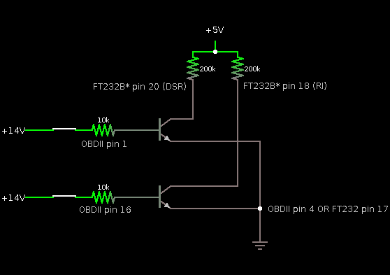


 I need ignation detection, so what can I do whit this?


Bookmarks