
 Member
The super interface
Basically i modify a usb kkl 409.1 Vagcom cable, it also can be modified to OPEL, FIAT and other brands but that's another story.
1# buy some Vagcom cable KKL 409.1, just 8 + shipping from ebay, ask the seller if it has the chip FT232RL. why? well basically because that chip support software mods.
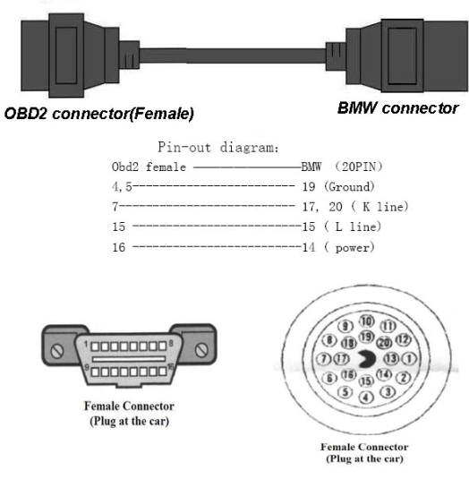
2# As my 530d do not have odb2 connector, I order a cable adapter from obd2 to 20 pin bmw, ebay seller is ( Car.Doctor ) another 8 + shipping.
I preferred to catch it on ebay, because it was more comfortable and cheaper than going to catch the pieces out there, also for those wishing to DIY, I leave the chart with specific connections.
3# Phillips screwdriver and the welder 4.25
4# Open your vagcom and solder obd2 pins 7 and 8, which are the K lines, otherwise you will not be able to access to all modules from the car
5# For the software mod, you will need this driver "CDM 4.2.1916 WHQL certified" , so unpack it, connect the cable, and install all with this driver.
Now we need to adjust the serial port, press the Windows key and Pause (both), then follow these images (sorry my XP is in spanish language)
Double click here
Select com1 and 1 or 2 ms of latency
6# Download the "M. Prog 3.5" to modify the programming of the eeprom FT232RL,
we need to invert RI # and DSR # signals to fool the detection of battery and ignition, in order to be able to encode.
Run mprog and follow this steps
check your I / O Controls settings, them must be like this:
#C0 = RXLED
#C1 = TXLED
#C2 = POWERON
#C3 = PWRON
#C4 = SLEEP
and do this
now you should see black dots
if your vagcom comes with ft232bm/bl chips, don't worry you only need to do some work
for those chips
pin 17 is GND
pin 18 is RI
pin 20 is DSR
so you need to solder pins 17,18 and 20 of the FTDI chip (this applies to the BL and BM) like this
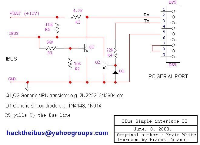
but if we want some REAL battery and ingnition detect, we must do this circuit
1 resistance of 4.7 kohm
1 resistance of 10 kohm
1 transistor BC546
in ft232bm/bl, it look like this
In case anyone wants to do it in the FT232RL here are the outputs of the chip.
Note: This interface supports cars from 96/98 to March 2007
it work's with inpa, carsoft 6.1.4 and navcoder also
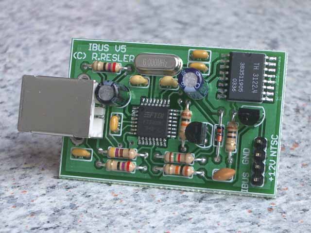
For the navcoder you usually need a RESLER interface but you don't really need it
The Resler interface works with 4 outputs (ibus, 12v, gnd and NTSC) NTSC signal is used to the camera and as we don't have the chip for its management, just forget about it.
With this in mind, connect three cables as follows
open your trunk and do this
OBD2 connector pin 16 to 12v Positive cable
OBD2 connector pin 7 to I-Bus cable
OBD2 connector pin 4 or 5 to negative (gnd) cable
now you can use navcoder or other i-bus software
Last edited by locum; 08-09-2010 at 06:27 AM.
Member
Thanks an awful lot man!!
Worked at the first try with INPA!
Last edited by Z3C Tblau; 09-01-2010 at 05:41 PM.
Member
BMW CCA Member
Can this work the otherway around? My D-CAN interface is based on that chipset (same drivers) - Would it be possible to use it on VAG cars?
Member
So just to clarify, if you have an FT232RL you need to connect pins 7 and 8 of the DLC connector, then install drivers and change settings. If you have an FT232BM/L you need to connect pins 7 and 8, of the DLC connector, pins 17, 18, and 20, then install drivers and change settings. For either of the chips, you can use your circuit to use the actual voltage of the vehicle coming from pin 1, which should be KL15, to ground DSR which is the handshake signal. Right?
Member
Could you please explain what I need to do with the K-Line interface to work as a resler interface as well.
I have FT232RL, and I did a software switch of DSR with RI and interace worked for me for a few months now but I'd liket o add Resler functionality. Do I just do that on top of what's already done?
what do these instructions mean (further modify the K-Line cable)?
open your trunk and do this
-- I'm assuming this means to open the blue OBDII connector of my existing cable?
OBD2 connector pin 16 to 12v Positive cable
OBD2 connector pin 7 to I-Bus cable
OBD2 connector pin 4 or 5 to negative (gnd) cable
what wires do I connect to these pins? and I was under the impression that we merged PIN 7 and 8 for K-LINE in the first steps of your instructions
or what does it mean with the last step for Resler interace?
Member
He's saying to run a jumper from the battery positive to pin 16, jumper from battery negative to pin 4 or 5, and jumper from ibus to pin 7. Then use your obd cable as an ibus interface.
Member
Hi the resler interface is for reading the ibus is this the mod that you are looking for?
Member
nope i don't mean to open blue cable, i think you should visit resler page and see how it connects his interface.Originally Posted by babenis

Anyway just plug it into your obd2 and start navcoder or connect it to your cd changer or radio, whatever.
you could search in wds for your car wires you will need 12v, gnd, and i-bus wich is usually a white and yellow cable
OBD2 connector pin 16 to 12v Positive cable
OBD2 connector pin 7 to I-Bus cable
OBD2 connector pin 4 or 5 to negative (gnd) cable
Nope, if you have BM/BL cable you will not be able to do software mod, that's why you solder pins 17,18 and 20 of your FTDI chip.
By the way if you don't solder the ignition detection circuit you will not be able to SET CAR MEMORY KEY.
Last edited by locum; 09-14-2010 at 08:37 PM.
Member
Hi !
I would like to build this cable to use NavCoder :
There is no way to connect it to the car with OBD2 connector ?
I would like to make the cable usable on more than one car...
I would like something that can be plugged on every car easily.
I have a CarSoft 6.5 interface but NavCoder does not work with it.
Thank you
Last edited by Orphee; 10-15-2010 at 08:01 AM.
Member
if i solder pins 17,18 and 20 of your FTDI chip.will i be able to SET CAR MEMORY KEY?
96 318is Sport --sold
96 528ia Premium Comfort seats --sold
98 528ia euro sport pack BR41880-- sold
01 530ia Premium CE52247
02 540ia Individual GG91507
(oOO)\(lll)°(lll)/(OOo)
BMW CCA Member
that with ncsexp yes
Alida:
Born: Friday, 9th January 1998
Arktissilber Metallic on Schwarz 528i/5
Claudia:
Born: Friday, 2nd May 2003
Sterlinggrau Metallic on Schwarz 540i/6
Member
No you won't
In order to do CAR MEMORY KEY you MUST do this circuit

Member
i made a mistake of not saving the original settings before programming the r232. would anyone know what the original settings were? im having a problem in mine where its all black dots but once i plug it in, the ign dot turns white and stays white even if i disconnect. after that, if i try to plug it in again, it goes black for a sec then goes back to white.
Last edited by toyotahachiroku; 10-16-2010 at 08:52 PM.
Member
your I / O Controls settings must be like this:
#C0 = RXLED
#C1 = TXLED
#C2 = POWERON
#C3 = PWRON
#C4 = SLEEP
Member
my cable must be different. those you have listed were not my original settings.
Member
Is it possible to add LED's to the wires for 12v+ and ignition on?
Member
I/O Settings!!??
m.Prog program does not have a "poweron" in dropdown menu, only "PWRON#" for C2.
Is this "POWERON" only a "glitch" in guide? =)
My chip is the RL-one.
Really good tutorial, pictures could be better. I got a TxFiFo problem when I started INPA 5.02 (txFIFO value=14, expected 8) Got that fixed by updatin OBD.ini file and that com port has to be Com1 no other, just won´t work, well on my laptop it doesn´t. (IFH-0027 error, Api init error).
For all you that have the FTDI 232RL chip. If you want to use the real battery/ign detection, you have to revert the DI#/DSR# with m-prog back to default, otherwise the black dots will still stay black even if the cable is not connected.
So leave other setting as they were in this tutorial, but take the taps of from DI# and DSR# and flash the chip.
How to connected the resistor/transistor mod see the included picture.
Bridge RI# to GND pin with solder (Pins 6<->7), the pin 9 is soldered to the BC546 leg with 4.7Kohm resistor. Remember! It wont work if the DI# DSR# is inverted on the chips software!

Last edited by poteroa; 10-22-2010 at 01:25 AM.
Member
I just messed up my cable with soldering! 3 pins of the chip joint when soldering...... Orderd a new one and need to get smaller tip on my soldering iron!
Last edited by IcemanBHE; 10-22-2010 at 05:28 PM.
Member
Is it possible to make it work with toyota yaris 08 ?
Member
Me too, i just order 2 more cables.
I hate when that happen
Member
here is my simplified real ign detection mod.
you don't have to use the 4.7k at the collector as in first schematic, the ft232 has a 200k internal pull-up .
also the base resistor has to be minimum 10k, i had an 120k one, the higher the better , lowers base current.
here are the simulation and pictures.

Member
It is possible use this interface with sss/progman v34 for update ecu and egs software??
thanks,
RYDE OR DIE . . .
Yes I have the same Vagcom interface and updated the DME. E46-330CI
Cable works fine with Progman/GT1/INPA.
Member
You can get the excessive tin off with solder remover wick (Copper Braid) or with a solder sucker that are sold in most shops that sell soldering irons. The cable is not broken yet, (If you did not connect the cable). So try that before you buy a new one. Its also good to have those solders "helpers" if you do more elect-jobs.
But yes, do not even think of starting the job with a humungus iron, and do not buy more that 40Watt iron, more heat=you will propably brake the chip or unsolder other parts from the board.
Oh, and there are lots of different sizes of solder, so get as thin as possible for those ic-legs, helps a lot.
Member
But can I update egs software with INPA or I must install sss?
With INPA ¿where can i download the software for my EGS?
thanks,
 Posting Permissions


 Reply With Quote


Bookmarks