
 БМВ Фанат!
If you have the wire in X20 (chasis side) you should be all set. This is the wire to power. I believe in most cases it is X20 pin 13 (Thick Grn/Vio - at least in my case).
And please, don't tell me that you cut off the X20 chasis side as well!
- 96 328is 6.0L. (LS1 to LS2 build thread: http://forums.bimmerforums.com/forum...ad.php?2098938)
- 96 328is 5.7L. (LS1 build thread: http://forums.bimmerforums.com/forum....php?t=1289987)
- 95 ///M3 6.0L. (LS2 build thread: http://forums.bimmerforums.com/forum....php?t=1619249)
- 97 ///M3. (e46 Fender Flares/track car build thread: http://forums.bimmerforums.com/forum....php?t=1727098)
- 96 328is (Dual Fuel Pump to Surge Tank thread: http://www.bimmerforums.com/forum/sh...ad.php?1964025)
Member
If you have not cut your wiring harness past the x20 connector you will be fine the rest of the wiring is in place.....the wiring goes down the drivers side of the car in the cabin.
Senior Member
Nope, just the engine side of the BMW harness. I was stupid, but not completely so, haha. Just wanted that BMW computer out of there and I couldn't reach all the plugs attached to the engine.
Member
Ie CommittedOriginally Posted by RahgBag

Then you should be ok with wiring up a new relay via the diagram and you'll be good.
Member
u good, no worries
Senior Member
Now I'm even more confused, haha. I did some research and found a couple articles that suggest this is the proper way to wire the fuel pump relay:
This was posted in Mateo's thread:
Translation: Pin 30 is +12V, 85 is ground, 86 is Chevy PCM, and 87 would be the BMW green/purple wire to the X20 connector.
Another:
-30 = constant [positive (+)] power (usually wired directly to car battery)
-85 = coil ground (wired to the negative (-) battery terminal or any grounded metal panel in the car)
-86 = coil power (wired to the control source. could be a switch, or it could be the car's IGN or ACC circuit.)
-87 = switched [positive (+)] power output. (when the relay coil is powered, lead/pin 87 is connected to lead/pin 30)
I think I'm going to try it this way and see how it works.
Also, how big of a relay/fuse should I use for the PCM? I would assume that it doesn't have to be a 40A like the cooling fans. I've got a 30A for the fuel pump and I'm going to use a 20A fuse like the stock setup does.
Last edited by RahgBag; 07-24-2010 at 11:18 PM.
БМВ Фанат!
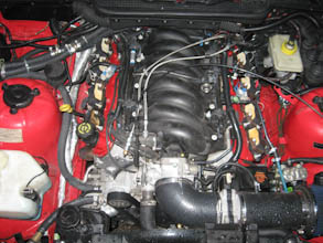
Guys, can you tell where you connecting this wire from LS1 harness? It looks to be something for starter??
Thanks!
- 96 328is 6.0L. (LS1 to LS2 build thread: http://forums.bimmerforums.com/forum...ad.php?2098938)
- 96 328is 5.7L. (LS1 build thread: http://forums.bimmerforums.com/forum....php?t=1289987)
- 95 ///M3 6.0L. (LS2 build thread: http://forums.bimmerforums.com/forum....php?t=1619249)
- 97 ///M3. (e46 Fender Flares/track car build thread: http://forums.bimmerforums.com/forum....php?t=1727098)
- 96 328is (Dual Fuel Pump to Surge Tank thread: http://www.bimmerforums.com/forum/sh...ad.php?1964025)
Member
ThaT isn't a starter plug on mine I just have a lug.
Member
You folks scare me sometimes
That is the starter solenoid engage wire, it is what tells the starter solenoid to fire.
Rob
Prior projects:
1998 540i with 6.6 LS2/T56 Chevy Power
- pictures and details
1992 325i with 6.6 LS2/T56 Chevy power - pictures and details
1995 M3 with 6.6 LS2/T56 Chevy power - pictures and details
БМВ Фанат!
Thanks rao, so I guess it should go to x20 pin 15 blk/grn wire then.
- 96 328is 6.0L. (LS1 to LS2 build thread: http://forums.bimmerforums.com/forum...ad.php?2098938)
- 96 328is 5.7L. (LS1 build thread: http://forums.bimmerforums.com/forum....php?t=1289987)
- 95 ///M3 6.0L. (LS2 build thread: http://forums.bimmerforums.com/forum....php?t=1619249)
- 97 ///M3. (e46 Fender Flares/track car build thread: http://forums.bimmerforums.com/forum....php?t=1727098)
- 96 328is (Dual Fuel Pump to Surge Tank thread: http://www.bimmerforums.com/forum/sh...ad.php?1964025)
AirborneDEN
This thread has been fairly helpful and clearer than most wiring threads/info. I see the wires that are being connected from the LSX DME to the BMW's wiring harness/x20. However, what about the body connectors like the C100, etc, that are part of the LSX wiring harness? Do those wire up to anything on the BMW?
Member
You should check out www.lt1swap.com where they have all of the wiring diagrams for the LSx motors, you'll find that most of the C100 connectors are power and ground wires if I remember correctly.
I know you are using an LS1 harness but this might be of some help for a general idea of what's going on.
http://lsxe36m3.com/?page_id=86
БМВ Фанат!
Yes, those connectors are like BMW's x20. You use the wires from these connectors to interface with x20.
- 96 328is 6.0L. (LS1 to LS2 build thread: http://forums.bimmerforums.com/forum...ad.php?2098938)
- 96 328is 5.7L. (LS1 build thread: http://forums.bimmerforums.com/forum....php?t=1289987)
- 95 ///M3 6.0L. (LS2 build thread: http://forums.bimmerforums.com/forum....php?t=1619249)
- 97 ///M3. (e46 Fender Flares/track car build thread: http://forums.bimmerforums.com/forum....php?t=1727098)
- 96 328is (Dual Fuel Pump to Surge Tank thread: http://www.bimmerforums.com/forum/sh...ad.php?1964025)
AirborneDEN
Thanks for the quick responses. The wiring part is not my forte, as easy as it should be.
AirborneDEN
Finally finished cross referencing the 98 LSX harness, OBD2 S52 harness, OBD1 S50 chassis, and the 99+ wiring guides that have been posted here, haha.
Just to kind of clarify, I have a few questions.
1. It shows that my harness does not have the DK BLU - A/C high pressure recirculation switch for my 98 LSX harness?
2. Is the PCM ignition and battery supply (on the C1 blue PCM) the ones that'll get connected to the BMW ECU relay's red and red/wht wires?
3. It seems like I am just missing something, but what do you mean when you say switch fuel pump relay control to pin 4 - swap pins 4 and 6? What location are you referring to when you say 4 and 6? Is this the correct way of wiring up the fuel pump relay? http://i31.photobucket.com/albums/c3...Untitled-8.jpg
4. Where does the X20 pin #13 - grn/vio connect to?
5. The ground wires (grey on the spreadsheets) are a bit redundant, as far as integration into the BMW harness goes right? Since you can just ground them without needing/use of the specific ground pin outs from the BMW harness?
6. The VSS wire is listed in the engine harness spreadsheet, but it doesn't seem like it gets used or connected anywhere?
7. How does the water temp (pin #72 brn/red on BMW harness) wire up to on the car/engine harness?
Last edited by Don Nguyen; 03-01-2011 at 03:15 PM.
Member
i'll take a swing at a few of those, as I don't have the diagrams in front of me but know a few of the answers
1 will depend on how you're wiring your AC - if you're running it off of hte BMW system or the LS1 system - it's easiest to wire the ls1 into the bmw and have the ls1 three way pressure sensor added into the AC lines of the BMW
4 - that is the obd2 wire if i'm remembering correctly - I swapped the pins in my under-dash obd2 port and wired that into the ls1 obd2 signal wire
5 - grounds are up to you - as long as they are chassis grounded at some point they'll be fine.
6 BMW VSS comes from the rear diff - you don't have to intermingle the LS & bmw systems as the ls1 has the t56 speed vss in it's harness and the bmw cluster has the rear diff speed - everything works fine seperately.
7 - you have to run a bmw temp sender in the passenger side block (the threads fit with the obd2 s52 harness - just have to lengthen the lead) - not sure how it will read in an obd1 cluster - leave the ls1 temp sender in the front drivers side head - it's on the same place (Flipped, obviously) on the passenger head that you thread the bmw temp sender into - the threads even match up - be careful threading the sensor in - i've found them to be very easily broken with very light torque)
AirborneDEN
Ah ok, those clears things up a bit.
I am going to be using the LS1 AC, but haven't looked too much into it yet, since I just want to get the car running first.
I forgot about the data link for that OBD2 wire, so I see where it gets used now.
For the temp sender, do you still need to wire up the factory temp sensor on the driver side of the head? I ask this, cause I actually broke mine, so if I don't need to wire it up to anything, it'll be one less thing I need to buy/replace.
thanks.
-Don
Member
I think we need to write a more concise LSx E36 swap AC wiring thread. It's still a bit of a dark area for me.
You'll want to have the data link and OBD II port working for factory reset stuff.
I think Braap and tong boy both wired in another OBDII port in the glove box.
Yes you need both temp sensors, the PCM needs to know how hot the motor is getting to adjust fueling and time accordingly.
I have an extra sensor if you need it, $15 is probably fair.
However being that you have a 98 I don't know if there is a difference.
AirborneDEN
They're different unfortunately. The 98 is 3 pin/wire while the 99+ are 2 pin/wire.
Can you clarify a bit on question 2 and 3 in my other post?
thanks.
-Don
БМВ Фанат!
Correction on #4: If you are talking about pin 13 from x20 on OBDII car which is thick green/vio wire, then it is Fuel Pump Relay.
There is no OBDII wire in x20. The OBDII wire is in the smaller of 3 connectors (x6031) pin 4
- 96 328is 6.0L. (LS1 to LS2 build thread: http://forums.bimmerforums.com/forum...ad.php?2098938)
- 96 328is 5.7L. (LS1 build thread: http://forums.bimmerforums.com/forum....php?t=1289987)
- 95 ///M3 6.0L. (LS2 build thread: http://forums.bimmerforums.com/forum....php?t=1619249)
- 97 ///M3. (e46 Fender Flares/track car build thread: http://forums.bimmerforums.com/forum....php?t=1727098)
- 96 328is (Dual Fuel Pump to Surge Tank thread: http://www.bimmerforums.com/forum/sh...ad.php?1964025)
Member
Yes, you want to connect them to your BMW relays, at least that is what I did for switched power. (I am going for a very clean factory approach to the wiring)
I was being more confusing and making things harder then they needed to be.
BMW uses a switched ground and a constant hot for the fuel pump relay. the pins are in reference to the pin numbers assigned in the ETM for my old '95 M3. However RhagBag's drawing is correct 100%. You can still use the factory wiring just switch the constant and switched and you're golden.
That is correct. There are however enough free pins in the X20 connector to completely remove the x6031 connector if you like. This is what I am doing because I already have my wiring harness done for the '95 OBD I car and it's now going into a '99 OBD II car.
AirborneDEN
Ah, I see those numbers now. I just saw how it was numbered, 30/85/86/87 before, but if you look at the electrical wiring diagram page in the Bentley, it numbers how you were referencing it to.
Looks like I can start the integration process now. Thanks for all of the help
Hopefully once I finish up my wiring and get it running, I'll be able to do a wiring write up for anyone who might end up using a 98 LS engine like me as well.
-Don
Member
This seems like the most appropriate thread to ask this CAN bus question, not to take away from Don's question.
I'm currently running a 2002 Camaro ECU. Unless I'm mistaken, it's a non-CAN bus OBDII setup.
I'm wondering if it's worth the effort to "swap in" a 2006 Corvette ECU and will I also have to swap engine wiring harnesss to do so?
The main motivation is to potentially run an aftermarket data logging system for track use like an AIM Pista MXL. With can bus, they are literally plug and play and can log all engine parameters in addition to track, GPS and G-force parameters.
Am I nuts for considering this?
John
Last edited by Maynor; 03-01-2011 at 07:21 PM.
John
E36 LS3
Member
John,
To be honest I don't know the particulars on canbus vs non can bus systems...
However I know that you will need to change a few things to get an 06 pcm to work with a cable throttle setup.
The harness will have to change or you can repin ( I have the connector) and possibly a few other minor changes as well. You will have to go to drive by wire... yuck in my opinion.
Ls1 tech might have some more answers for you... ill reseach it tomorrow as well.
Paul
Member
Yeah, I have no desire to go drive by wire. I'm fine with cables. I was hoping that was an ECU tuning thing you could switch on and off but you're right, more research needed.
Thanks Paul.
John
E36 LS3
 Posting Permissions


 Reply With Quote


Bookmarks