
 Member
Like everything else Bert (including the somewhat curious phenomena of miniature candy bars costing the same or more than a large Big Hunk?) nothing good lasts forever...and YES, all the good stuff was the first to 'leave the building'...likely back when one could actually afford the UPS charges to send an 85 lb. transmission to your associates for Thanksgiving, that is if you had inclination to do so...Originally Posted by Bert Poliakoff

More than ever, I am convinced that being able to find acceptable parts is the key and researching same is the task at hand...and of course a solemn promise to oneself to not buy junk, even though one is severely tempted to do so and say..."heck, it's only this month's rent money"...indeed this new concept might work in our favor, (eventually?) mostly to help separate the boys from the men here, when it comes to harnessing 300+ horsepower to a 40 year old diffy mount, and expect nothing to go amiss more than convenient walking distance from home base...
I only offer what I see Emil...Any temptations are purely reactionary and exist solely in the private mind of those brave enough to even attempt the job you have almost successfully completed...
Bravo!
Just remember, as Plato wisely wrote in his novel on consistency... " Don't fu&k it up now!"
Member
Nov-22-09: Today I removed the drive plate, rear main seal carrier, and replaced the rear main seal. I had to remove the carrier solely because the seal did NOT want to be removed. It took quite a bit of persuasion to remove it (don't worry, there was no prying done), but it did eventually come free, and a new seal was installed with the help of a 4" PVC end cap. In removing the carrier, I noticed that the oil pan gasket has deteriorated and is crumbling, causing some oil seepage, so it will have to be replaced. I also noticed that a plate at the back of the head is seeping a bit of oil... it's probably better to replace it now while it's easier to access.
Here's the centre support bearing and carrier installed:
I installed the pilot bearing but unknowingly installed it too far in, so I had to remove it. Unfortunately, it appears that the bearing didn't want to be removed, so it broke apart in the process of removing it. Another one is on order... Live and learn, I suppose.
Dec-02-09
The pilot bearing, flywheel, clutch and pressure plate have all been installed! The pilot bearing itself fits into the 'hole' in the back of the crankshaft, and is supposed to sit a bit further in from where it would be flush. Since it is a sealed bearing, it does not need require grease to be applied to it prior to installation, and it does not need the additional pieces (such as the foam and cap, etc) as shown on RealOEM. All you need is the bearing, that's it. However, I did lightly grease the outside of the bearing to allow it to slide into the crankshaft easier, and with the use of a 24mm socket and rubber mallet, it was tapped into place. Next up was the flywheel and flywheel bolts.
The flywheel I'm using is a 14lb unit out of an E12 528i, which happens to be the same as the flywheel in a 533i/633CSi/M5/M6, but without a tab built into it for the motronic bellhousing reference sensors (since my car has an M30B35, there are no bellhousing reference sensors). 8 flywheel bolts held it in place, all torqued to 77±5 ft-lbs (I did 82).
Next up was the clutch and pressure plate; I opted to use a Sachs M635 setup. Included in the Sachs kit was also a throw-out bearing, and a packet of grease needed to lubricate the spines of the clutch, which is what you should do. Now, I have to make this clear: you NEED a clutch alignment tool. I could see this job being next to impossible without one, as the clutch doesn't have a spot where it centres on its own. I bought one off of PelicanParts for $10, and I suggest you do the same if you are doing this job. The pressure plate fits overtop of the aligned clutch, and is bolted down with 6 bolts. All that was available locally to me was the 8.8 grade bolts (the manual recommends you use 10.9 grade bolts), but I'm sure it will be fine. The manual also recommends you tighten these 'uniformly', so I first finger-tightened all the bolts, ensuring that the clutch itself was perfectly centred and that I could slide the clutch alignment tool in and out without resistance or excess friction. With the torque wrench, all tightening was done in a criss-cross pattern, torquing the bolts in stages. I believe the 8.8 grade bolts are to be torqued to 18 ft-lbs.
Now for the first time ever, my 6er has a clutch! Now I need to figure out if I want to keep the sheet metal shifter console on the transmission, or upgrade to an aluminum shifter console. The aluminum one is adaptable to the Getrag 265, but it requires an adaptor bracket, found on the E30 M3. Then, it's a big mystery as to if a normal aluminum shifter arm from a 6er will work, or if I need to use an E30 piece. I'm guessing the 6er parts will work, but who knows. Any ideas?
I also think it's time to tidy my workspace
Looking at that photo, I may want to consider painting my brake calipers and disc rotor hats to prevent rust from building up...
Also, I'd like to apologize for the lack of pics as of late, as I've been having trouble convincing my friends to come over and take pictures for me as I work. It's also a pain to take these photos while under the car, but I'm going to do my best.
Cheers,
-Emil
Last edited by SixerFixer; 12-02-2009 at 02:05 PM.
Impractical
Moderator
Great job. Agreed about the clutch alignment tool being necessary--it's essential for any clutch job, really, unless you can fabricate a wooden one on a lathe or some such.
I love this thread.
-Matt
Current: '94 MX-6 V6/5 '72 240Z '10 Mazda5
Past: '02 330i/5 '85 RX-7 GSL-SE '95 540i/6 '95 525i/5 '86 635CSi/5 '88 JZA70 '86 4K quattro '85 RX-7 S
Wish list: Type 44 Manta Pre-'85 CGT 405 Mi16 SVX W123 Coupe
Expired
Check this link..
http://www.mye28.com/viewtopic.php?t=59684
he used an M5 Shifter arm for a 280 and put it on a 265 with chopped ears.
So you'd need these parts/linkage
but you want 2&5 thats not on that list.. hmm.., but that's the shift arm for sure he used
Looks like 25-10-1-220-571 is the same arm for both m5 and m6 with a 280 box.
Here's a link to Real OEM for the E30 adapter bracket.. and what appears to be the bolt/nut that didnt show up (as 2&5) in the prev. RealOEM link.. which would be 6 & 5 in this diag.
http://www.realoem.com/bmw/showparts...81&hg=25&fg=05
25-11-2-225-369 is the number for the "bow" bracket you adapt the 265 to the arm with.
I been trying to figure this one out for awhile and thats got to be the correct arm to work with the bracket like he setup on his M5.
Last edited by Seeker; 12-02-2009 at 10:13 PM.
Member
Did you ever get this done? I am going to be picking up a 1980 635SCi with an auto in it and I really like the way you are doing this DIY. I am not sure all of what you are doing will apply, but whatever additional input you have will be appreciated.
Trever
Member
i just picked up an 86 635csi slush box that is more then on its way out. any more updates
11/85 635csi auto
Member
Well I am wanting to know how you refurbished the BBS. I have a pair I am trying to complete. Hand polishing with a dremel is the slow way.
I am my country's keeper, my President and Congress report to me, and so I will stay informed and involved. I will make my voice heard, and not just at election time. I can make a difference I matter. I am an American
I choose to trust in you O Lord the leader of my Life and my household. In your name.
Member
Hookay... It's been a while! Sorry for the incredible delay since the last update, but I had to sort out a few things in my life. I can, however, report that I've completed the swap and taken many photographs since my last update. I haven't had a single issue whatsoever; the 6er drives and performs just as it should had it originally come with a 5-speed.
Bear with me for a little while, I just need to sort the photos I've got and complete the writeup. I forgot to take a few photos, namely the setup of the shifter linkage, installation of the actual gearbox, and popping in the driveshaft, but I promise that I will make a trip back in there in the spring/summer and make up for those. I'll try and get this writeup done in the next couple of weeks!
Next up on my checklist was to finish tackling the electronics. The automatic wiring harness has already been removed, leaving us with just the remnants of the auto gearbox wiring in the engine wiring harness. Stemming off the bundle of wires making up the ECU connector is another connector that communicates with the automatic transmission wiring harness. 3 of the wires in this connector actually go to the throttle position sensor.
From the '88 ETM, this connector is referred to as C133 and has several wires going into it. The ones that we're interested in are the 3 brown ones. In my instance, the wires were solid brown, yellow, and black. Refer to your ETM for exact colours. Anyways, these three wires go directly to the throttle position sensor, attached to your engine's throttle body.
My automatic car has a six-pin sensor:
Manual cars have a three-pin sensor:
I wasn't 100% sure if the car would run right if I left the automatic sensor with all the automatic wiring ripped out, so I chose to convert the harness to the three-pin setup. I simply cut the old 6-pin connector off and cut open the tubing containing the wires to reveal what I was dealing with. The throttle position sensor harness is made up of 2 different parts: the first part is comprised of the brown/black, brown/orange, and brown/green wires that are the same as the manual throttle position sensor connector (these wires are all loose once you remove the tubing housing all the wires). The second part is an isolated set of wires in their own tube, comprised of the brown, yellow, and black wires that we wanted to eliminate:
What I did was simply tuck them out of the way under the plastic wiring cover found on M30B35 engines. Now, all we have left to deal with are the 3 wires that are the same as the ones found in the manual TPS connector.
Using a connector that connects to the TPS on an E30 that I snipped off a dead 325i at the junk yard (which happened to have the exact same wires in the exact same place as another harness that I have that I didn't want to butcher), I soldered the wires together, heat shrink wrapped them, and put the whole thing back together, replacing the automatic TPS with the manual TPS:
Doesn't look too bad, does it?
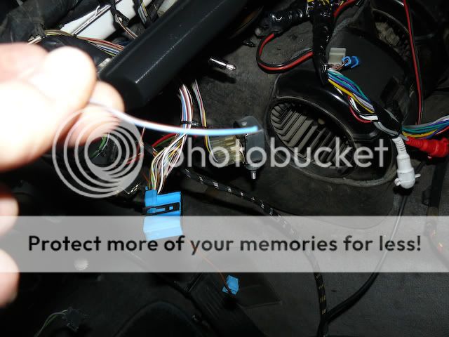
The last important bit of wiring that needs to get done is to ground the park/neutral indicator connector from the range connector for the cluster. From the automatic wiring harness removal, you may remember a blue wire connecting to the range selection connector that tethered the body harness and the automatic wiring harness together.
That wire is the one that we need to ground. I crimped an o-terminal connector to the end of that wire and found a grounding point under the dash to which I grounded the wire. Doing this basically tells the ECU that the car is in neutral or park, so it's OK to start the vehicle if need be. From my understanding, if you don't do this, the vehicle won't start once you're done the swap!
Next update will have bigger and better things!
Last edited by SixerFixer; 01-08-2011 at 03:36 AM. Reason: Automerged Doublepost
Member
I would like to add though that the tps from the 3 series and 528e does not work. it looks the same but rotates in reverse... the idle position is wot. a tps from a manual m30 is required. Did this today and made 2 trips to the junkyard.
-Kelvin
Member
Currently doing a swap and noticed that the pedal box "frames" look pretty much the same, excluding the pedals of course and the two zinc Chromated brackets that come with the manual version. So having the longer bolt that comes with the manual; both the clutch and brake pedals fit right in the standard auto pedal frame. Is there a reason as to avoid this step? This would certainly reduce the swap time by not having to replace the pedal boxes and removal of the steering column...
Old School Punk
It's actually easier to remove and replace the whole assembly.
The spindle (long bolt) that goes through the pedals is tedious at best to R&R in place.
It only takes 20 minutes to swap in the already assembled pedal box.
Also, be sure to attach the master and the feed line before installing the pedal box.
The feed line can be a pita.
Last edited by ShapeShifter; 11-21-2012 at 01:32 AM.
Member
I guess that luck was on my side.... when I removed the pedals out of the donor 5er and then R&Rd back into the 6er :-)
Member
Part number? I can't find it on RealOEM.
WARNING: Zombie Thread!
 Posting Permissions


 Reply With Quote


Bookmarks