
 shade tree mechanic
Moderator
shade tree mechanic
Moderator
Location of the 2 fusible links on an E32 http://www.bimmerboard.com/forums/posts/377728/
and more details on my website on fusible links http://twrite.org/shogunnew/data/electrical.html
Shogun tricks and tips for the E32 series are HERE!
shade tree mechanic
Moderator
Importance of functioning donuts, cyl. identification sensors M70
I just read in the German forum about a case where someone changed on his M70 distributors, rotors, spark plugs and ignition wires on cylinder 6 and 12 and re-used the old donuts. Then he had trouble. Engine starts, runs short time with increased RPM and then dies. EML lamp goes on with ignition on and then goes out again as it should be. Diagnosis faults: fault ignition cylinder 1-6 and 7-12. That was 2 weeks ago. Today he fixed it. He noticed that he installed the cylinder identification sensors/donuts/pulse generators on ignition wires cylinder 6 and 12 the wrong way. Turned the donuts the correct way and engine runs starts and smooth. Apparently there no direction marks on the original ones, if I remember correct.pics from ECS website, original
https://www.ecstuning.com/b-genuine-...e/12121725020/
Aftermarket pics based on this website info
Facet 9.0103
https://boodmo.com/catalog/part-sens...ssion-2453507/
ERA 550277
https://boodmo.com/catalog/part-rpm_...ement-2847082/
MEAT & DORIA 87418
https://boodmo.com/catalog/part-rpm_...ement-2886417/
no pics available from SIDAT 83357 + Hoffer 7517418
This is not the first time that I read that when donuts are not working properly or the ignition wires/plugs # 6 and 12 are not functioning, there will be engine problems. So if the M70 starts, idles for some seconds, then dies, also check the ignition wires, plugs and donuts from cylinder 6 and 12.
The usual cause of running for a few seconds and then stopping is the lack of cylinder identification signals. These are provided by the inductive sensors on HT leads 6 and 12. When you get a fault with INPA ti-signal, this is the injection time signal, the base timing is derived from the cylinder identification signal. We had the same problem some years back on an 850: lack of cylinder identification signals. In our case the ignition wire boot of cylinder 12 was lose/not connected to the spark plug.
Before we checked the usually subjects like fuel pumps, fuel pressure, ignition = distributors + rotors, crankshaft position sensors.
The car is telling you what is wrong, the CID sensors...
Make sure you have them plugged into the right plugs?
Make sure they are actually any good? Bad "donuts" have been a common problem with some replacements...(aftermarket).
Another comment: Friend had same sort of problem a while back, motor would start and then died shortly thereafter. He'd brought it used from out of state. I had a suspicion after listening to the motor start and die a few times that not all cylinders were firing. I took a look and found they were from a 3 series! Popped in a spare set from an M70 and the car fired up and purred like a kitten. Turns out original owner sold car because it kept shutting off.
So important is, when you change ignition wires and re-use the old donuts, make sure the donuts are installed the same way as original, not flipped.
comment by Johan: Motronic 1.2 doesn't report this as an error
comment by shogun: so only DME 1.7 ? maybe in connection with the changes for the cat protection system, I assume.
Catalytic converter protection function - Ignition circuit monitoring
The ignition circuit is monitored by the cylinder detection sender (pin 16) on ignition line 6 (or 12). If it detects no ignition signal on ignition line 6 (or 12) , the fuel supply to the relevant cylinder bank is cut out by shortening the injection signal. The sender monitors the entire primary side of ignition, and cylinder 6 or 12 on the secondary side. I tested that in 2009 on my 1988 750 with M1.2 but the result was different: http://www.bimmerboard.com/forums/posts/660913
And Timm from the U.K. forum mentioned: "The sensors on ignition leads 6 and 12 are not there to disrupt the injector duration, they are there to identify the camshaft position and are a direct forerunner of the camshaft sensor. The sensors are called 'cylinder identification sensors' and detect when cylinders 6 or 12 fire, they do not measure the primary circuit, how could they, they are stuck on the ignition leads! This is not part of the EML system, any failure will not light the EML indicator. It is a basic ECU input that is found on straight-6's that do not have EML as well as EML variants of both the M30 and M70. Without the cylinder identification sensors, the ECU's do not know which of the two unique revolutions the crankshaft is on. This does not matter to the ignition as the spark is directed to the correct cylinder by the distributor. It does matter to the injection circuits which should fire every two crankshaft revolutions or every one camshaft revolution.During cranking the only reference signal is the crankshaft sensor and 'double injection' is maintained until the ignition from cylinders 6 and 12 are detected. From this point on the ECU is aware of the correct camshaft position and can fire the injectors every two crankshaft revolutions. If the cylinder identification sensors fail to detect ignition pulses then the injectors continue to fire every crankshaft revolution but the injector duration is reduced to prevent damage to the catalytic converters." http://www.bimmerboard.com/forums/posts/1221671/
comment by rv8flyboy: interestingly the DME here in USA will set the CEL upon donut problems. At least by my experience. I was running the wokke chipset and had a very rich mixture problem, wasn't till I scope'd the signals that I noticed one bank the injectors were firing alternately (correct) and on the other bank both sets of injectors were firing at the same time. Turns out I lost the donut signal. No CEL. I installed the Dinan chipset just for kicks and lo and behold, when I disconnect the donut, it pops the CEL. Talked to Wokke at length and although the CEL was mandated here in the US, it wasn't mandated to the same extend in Europe for a while so euro versions of the DME would be more cavalier towards problems such as a missing donut. CEL, what CEL?
The Wokke chipset was based on the euro DME, the Dinan set appears based on the USA DME. I am now running Dinan DMEs and a Wokke EML, partly because I want the CEL function. Shogun's chips are based on Euro DMEs.
Crank and Cylinder Index Sensors M70 https://www.bimmerforums.com/forum/s...identification
Shogun tricks and tips for the E32 series are HERE!
shade tree mechanic
Moderator
M30/M70 ignition system data accdg to Bentley
Coil primary, coil code # 2051118335 terminals 1 (-) and 15 (+) resistance 0.50 ohm
Coil primary, coil code # 20510171101 terminals 1 (-) and 15 (+) resistance 0.37 ohm
Coil secondary, coil code # 2051118335 terminals 15 (+) and 4 (ctr. resistance 6.0 kohm
Coil secondary, coil code # 20510171101 terminals 15 (+) and 4 (ctr. resistance 9.0 kohm
spark plug ends 5.0+/- 10% kohm
shielded plugs 1.0 +/- 20% kohm
spark plug wires 0 ohm (approx.)
rotor 1.1 +/- 10% kohm
M70 firing order: 1-7-5-11-3-9-6-12-2-8-4-10
crankshaft position/rpm sensor:
540+/- 10% ohm
from workshop manual
distributor rotor 1+/-20% kohm
angled/shielded connectors 1+/- 20% kohm
spark plug connectors 5+/- 20% kohm
cylinder identification sender coil resistance at 20 degree C (68F) <1 ohm
pulse sender/crankshaft position sensor coil resistance 540 +/- 10% ohm
temperature switch for e-box cooling E32 750: switch on at 44 +/- 3 degree C, switch off at 36 +/- 3 degree C.
transmission: This is very important, download it, 11.5 MB , Tech guide link with test data for all the valves and the resistance in ohms , different valve bodies etc http://parts-at.ru/wp-content/upload...Tech-Guide.pdf
Imbalance - Irregular Running and Its Causes
Imbalance
An imbalance usually manifests itself as irregular running and vibration through the entire vehicle or in the steering wheel. It often occurs only in certain speed ranges. If vibration also occurs when the engine is disengaged and in certain gears, we can assume that the wheels and tyres are the cause. An imbalanced wheel can be seen as being a perfectly even wheel assembly which has an extra weight at one point.
The imbalance comes about through an uneven distribution of the mass. One talks of either a static or a dynamic imbalance, depending on the particular distribution that prevails.
With a static imbalance , the weight in the wheel assembly is not distributed evenly. If a segment of the circle is heavier than the others, this would rotate a freely rotatable wheel until the heaviest segment is at the bottom.
This, however, is not the actual cause of the irregular running characteristics. This is caused by the fact that centrifugal forces act on all the segments when the wheel is rotating . These forces are greater the heavier the particular segment of the circle is.
When the mass is distributed evenly throughout the wheel assembly, the centrifugal forces active on opposite sides of the wheel cancel each other out, which means that the wheel axle is not moved out of its normal position. An uneven distribution of mass, however, causes an uneven distribution of the centrifugal forces. These forces no longer cancel each other out and consequently cause the elastically mounted wheel axle to oscillate. Even if a wheel assembly is not suffering from a static imbalance, it can start to run irregularly as soon as it is set in rotation. This irregular running (e.g. vibration in the steering wheel) can in this case stem from a dynamic imbalance. To be able to draw up a picture of a dynamic imbalance, imagine the wheel cut through vertically in the middle. The cause of the irregular running is an uneven distribution of mass in the front and rear halves of the wheel. These variations do in fact cancel each other out in the sense of a static imbalance, i.e. the centrifugal forces are of equal strength, but they do not act upon the same point in the axle. They therefore set the axle into a wobbling motion. A dynamic imbalance becomes particulary apparent if wide tyres are fitted. This is why wide tyres must be balanced with great care. Static and dynamic imbalance generally arise together and their causes will be found in both the tyre and the wheel. If an imbalance is detected, note the speed range in which it arises.
The following rule applies for BMW vehicles:
Vehicle speed = 80 - 100 km/h Front axle affected
Vehicle speed = 140 - 160 km/h Rear axle affected
An imbalance in a wheel assembly cannot be removed, since it is caused by different distributions of mass in the disk wheel and tyre. The imbalance can, however, be compensated for by attaching a balance weight at the appropriate point.
Other causes of irregular running
If a customer still complains of irregular running (e.g. vibration in the steering wheel) after balancing, this may be caused by a wheel running out of true. This is caused by variations in the production of tyres and wheels, which have the effect that the wheel assembly deviates from the ideal circular form. In the case of radial run-out , the height of the axle changes constantly as the wheel rotates on the road. In the case of lateral run-out , the wheel wobbles.
Radial and lateral run-out can be determined on the balancing machine. The well centred wheel assembly runs on a dial gauge. The radial run-out is measured by scanning the contact area, while for the lateral run-out the sidewall is scanned. During measurement, attention must be paid to the tread grooves and markings on the sidewall. The cause of radial and/or lateral run-out may be found in the tyre or in the disk wheel. Radial run-out and lateral run-out of a disk wheel are measured at the rim bead seat and inner flank of the rim flange.
The permissible radial run-out must not be exceeded:
Lateral and radial run-out - alloy up to 0.6 mm
Radial run-out of wheel assembly at tyre - up to 1.0 mm
The influence the lateral run-out has on vehicle handling is considerably less than that of the radial run-out. Another cause of irregular running are fluctuations in the radial force . As it rolls, the tyre is pressed in by the weight of the vehicle. A measure of this is the radial force. Variations in the constitution of the materials cannot be eliminated through balancing. They lead to different degrees of compression and thus to untrue running. Fluctuation of the radial force causes the axle to jump, in the
same way as a wheel assembly with radial run-out. The cornering force can also fluctuate (lateral force fluctuation), but the affects of this are only minimal. These variations cannot be determined with the resources available in a workshop and can only be eliminated by replacing the tyre affected.
Another cause of irregular running can be flat spots on the tyres.
These can arise, e.g. if a vehicle is left standing for a longer period of time (e.g. overnight) to allow the paint to dry after a respray. Temperatures of up to 80° C then occur at the surface of the tyres. These temperatures are reached despite heat shields being placed over the tyres if the vehicle stands long enough in the heated spray cabin. Flat spots develop on the tyres, which cannot be lessened by taking the vehicle for a long drive on the road. For this reason, a vehicle which has been resprayed should never be left overnight to dry in a warm place. If this cannot be avoided, the vehicle must be placed on chocks and the wheels removed. In the course of normal respraying work, a temperature of about only 60° C is reached on the tyre surfaces and this is not critical if the vehicle is dried for the normal length of time.
Flat spots can also come about due to the weight of the vehicle if the vehicle is parked immediately after being driven at high speeds without the tyres being given an opportunity to cool down somewhat.
A flat spot can be returned to its original shape by taking the vehicle for a quiet drive, warming up the tyre and then letting it cool down.
http://www.meeknet.co.uk/E31/Timms_b...20Problems.pdf
Last edited by shogun; 05-14-2018 at 09:12 AM.
Shogun tricks and tips for the E32 series are HERE!
shade tree mechanic
Moderator
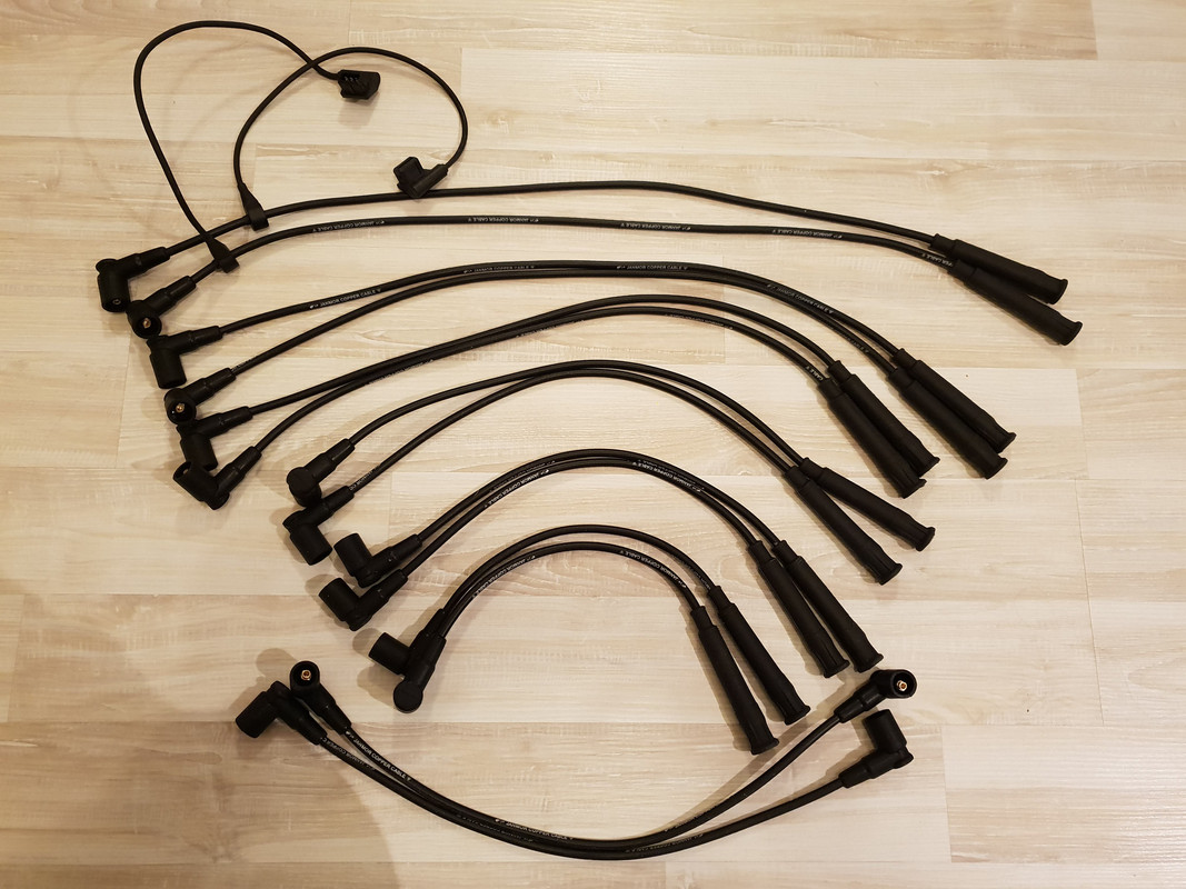
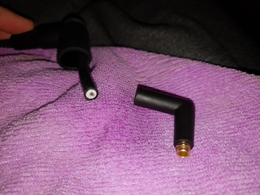
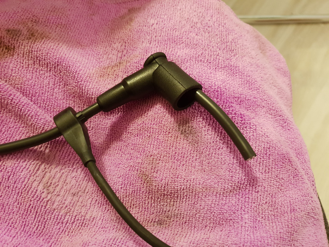
Here's a quick & simple write up with pictures for installing cylinder identification sensors aka donuts on wires #6 and #12 on aftermarket ignition wires with woodscrew boot/plug on the distributor side.
These wires are identified by comparing length with the rest of the wires, them being the longest ones obviously. On the distributor boot end of the wire, get a slim flat blade screwdriver and slide it between the rubber boot and the wire. Use a lubricant of your preference, in my case WD-40, and spray it liberally. Follow up with more lubricant into the boot opening.
Work it in and you should be able to simply slide over the rubber boot towards the inner part of the wire like this. Hold the wire and push on the boot, don't pull on the cable. Use more lubricant if necessary as you don't want to pull on the wire and stretch it.
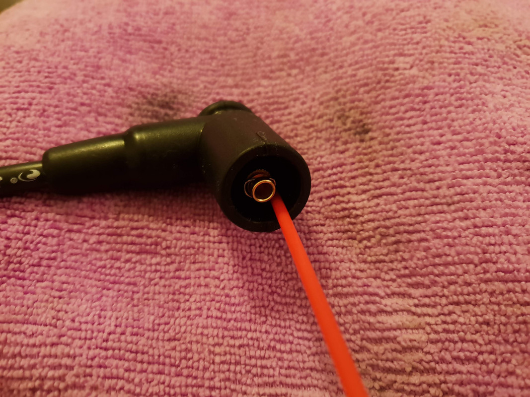
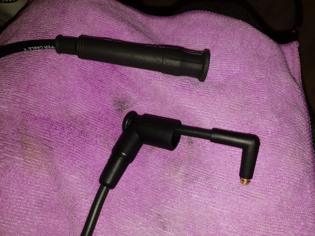
Grab and hold the wire with a microfiber cloth (for better grip) and start unscrewing the plug in anti-clockwise direction. It takes a decent amount of force to unscrew the plug so don't be afraid to use it as you can't really do any damage here.
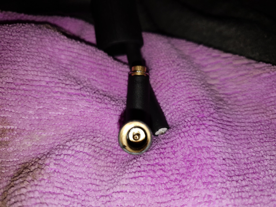
The plug simply unscrews and the woodscrew inside looks like this.
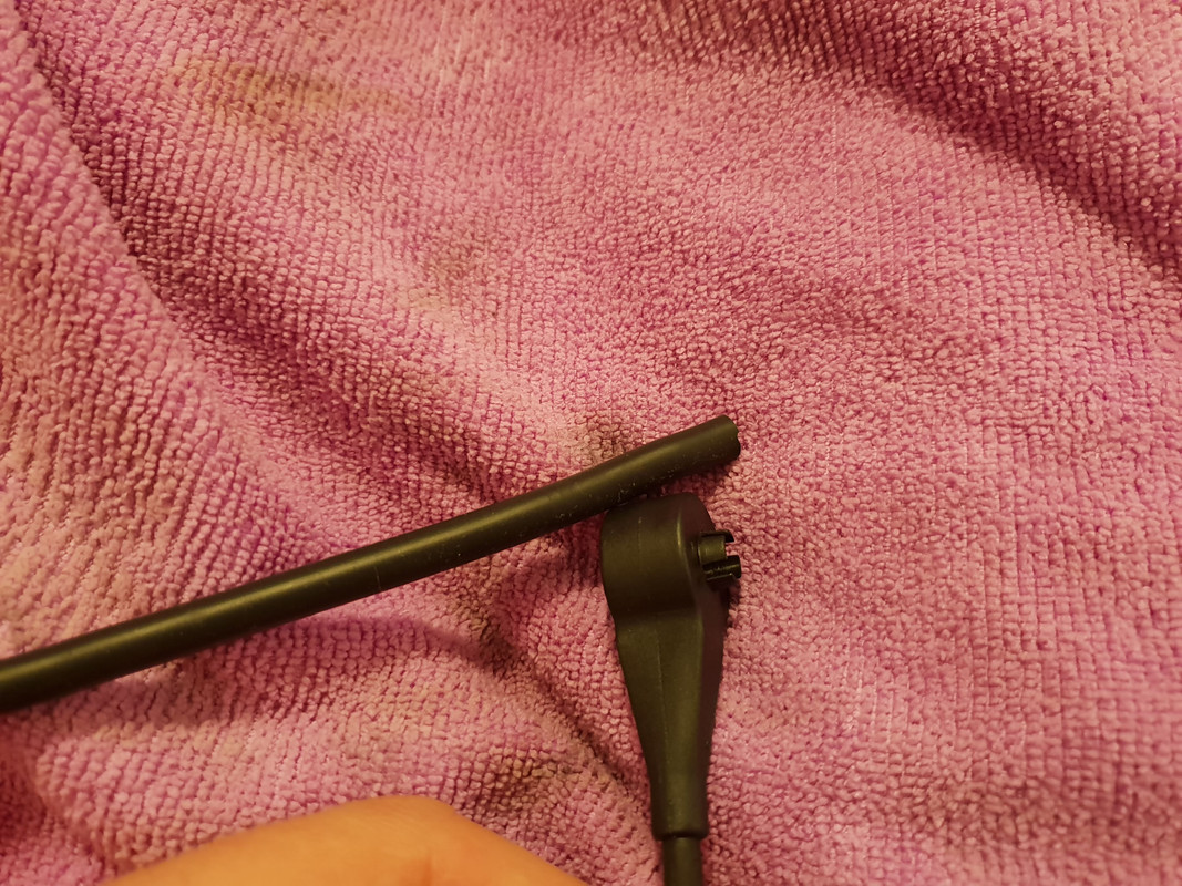
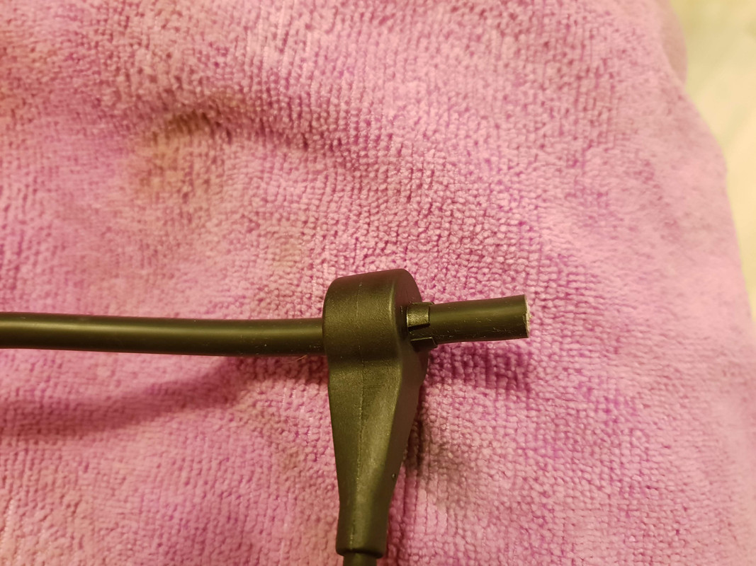
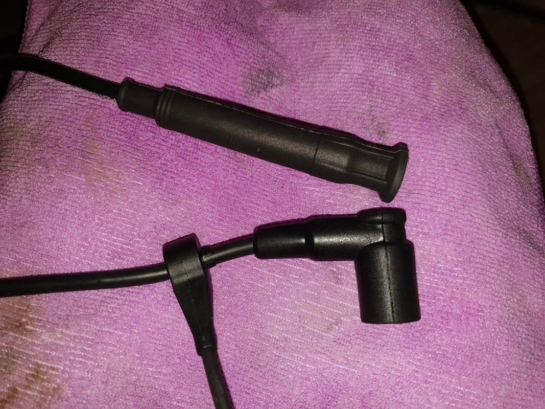
Remove the rubber boot from the wire and it's time to install the cylinder identification sensor. The direction in which the sensor is installed matters. If you are reusing your old sensors, simply install them using your old wires as a reference.
Important!: If you are installing new sensors, as I did, the 4 tips/prongs should be pointed in the distributor cap direction like this.
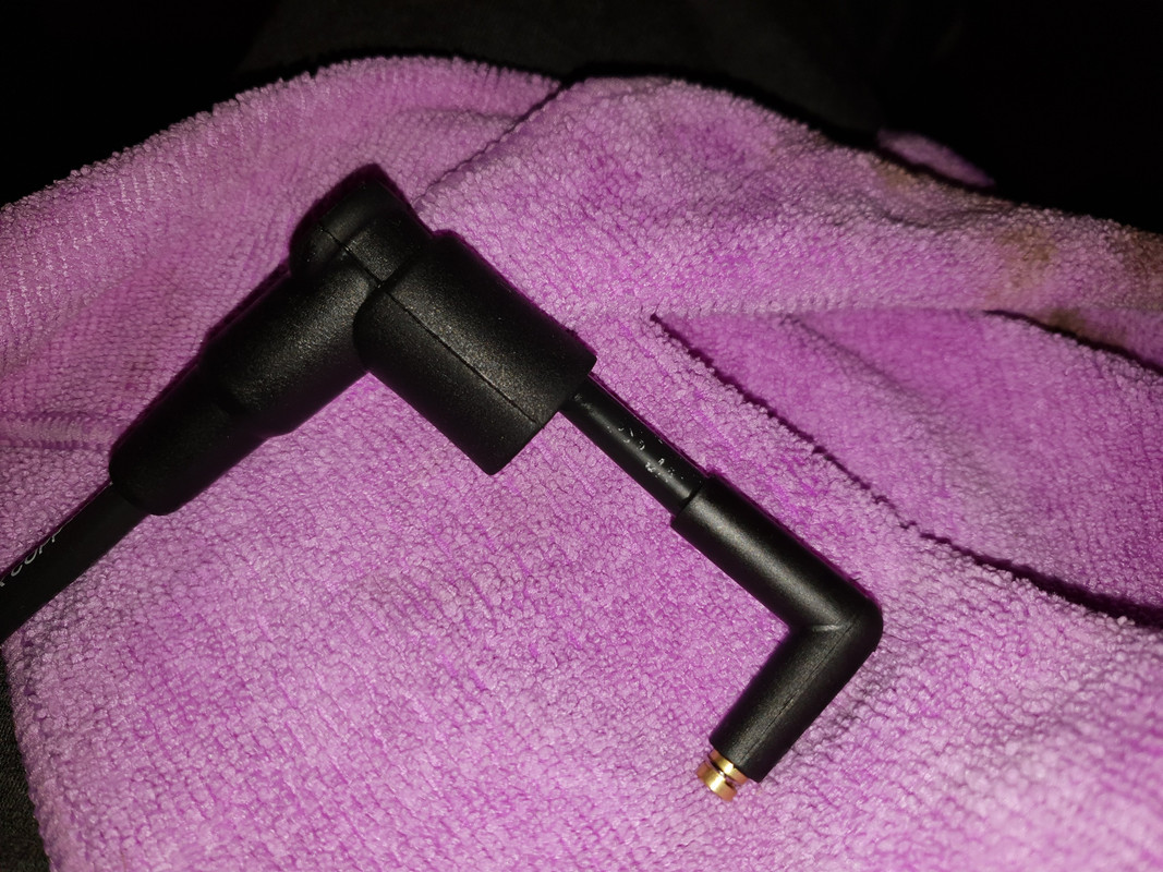
Lubricate the rubber boot and slide it back onto the wire.
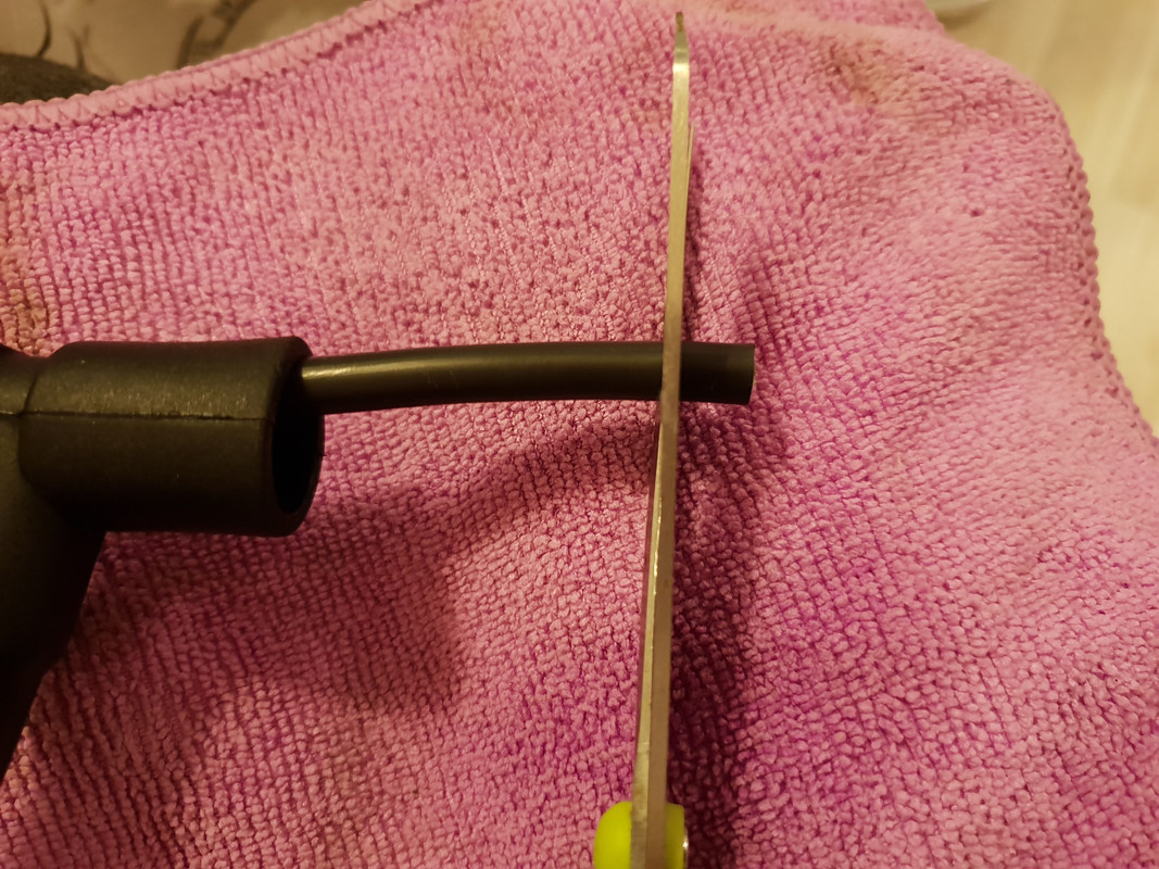
Grab a pair of sharp scissors and cut off 3 mm of the end of the wire thus getting a fresh bit of the wire where the woodscrew will go in.
Apply WD-40 on the end of the wire and reinstall the plug by screwing it back into place in the clockwise direction. Slide the rubber boot over the plug, if needed use more WD-40 to help boot slide easier without putting stress on the wire.
Now we want to verify that we have a proper connection and installation was successful. Break out your multimeter and set it to measure resistance (Ω).
Stick a test lead at each end of the wire and you should be getting a readout of around 6 kOhm. This goes for all 12 wires, spark plug boot is 5 kOhm and distributor cap boot is 1 kOhm.
The wires for ignition coil to the distributor cap is 2kOhm. That are the ones with the 2 angled boots
Additionally, you can wiggle and bend the wires slightly to make sure the connection is constant and doesn't drop.
Shogun tricks and tips for the E32 series are HERE!
Member
More input on shimmy: Mine had a bad shimmy when lightly tapping the brakes at speeds of 50-65 mph. I did all of the aforementioned repairs, new control arms & thrust arms & bushings, tie rod ends, idler link, had the tires dismounted and measured the wheels for runout, did a road force balance on the approx. 50% worn tires. New hubcentric rings. Basically everything per the previous posts. The braking shimmy still persisted. I removed the wheels, wire-brushed the front hubs and both inside & out of rotor hub faces. Measured runout of the hubs -- perfect, measured runout of front & back side of the rotor braking surface, rotor thickness variation negligible. Everything was well within BMW spec per Bentley's. I decided to have the rotors turned anyway and installed new OE BMW caliper guide pins and bushings -- problem solved! I think the caliper guide pins and bushings were the problem all along.
As for the rough idle (m30), I installed new eccentrics and adjusted the valves. Measured the DME temp sensor (blue one on the thermostat housing closest to the head). It was about 100 Ohms below Bentley's spec at operating temp. I inserted a 100 Ohm resistor in series with one of the sensor wires. New Bosch "Silber" plugs all gapped at .032", idle much improved with only a slight occasional stumble when warm.
Last edited by TheStigg; 12-22-2018 at 12:15 AM.
"The US Olympics bobsled team has renamed their sled 'Biden' because nothing has taken America downhill faster"
TheStigg (aka "gale")
92 735i 5-spd, turbo pending
89 535i 5-spd (may she rest in pieces)
94 325ic 5-spd
87 325is
shade tree mechanic
Moderator
Changing the original spark plug boot on M70
changing the original spark plug boot, from a German E31 forum regarding M70/S70 ignition wires, seems in most cases the long boot going to the spark plug is the problem, the resistor inside the long boot get’s bad over the years,
German text
Beim M70 werden Zuendkerzenhersteller 5000-OHM 12121710707 benoetigt. Ich moechte beim S70 Motor die Zundkerzenstecker wechseln. Ist es wirklich so aufwendig, wie es in der Original BMW Reparaturanleitung steht? Laut dieser braucht man hierzu mehrere Spezialwerkzeuge....Laut dem aktuellen BMW Ersatzteilkatalog finde ich folgende Teile, kann mir jemand sagen,ob das so vollstaendig ist + warum 3 Teile ausgewiesen sind:
- Kerzenstecker/: Nr. 12121710707 , -Isolierhulse: Nr. 12121736142 ,- Rundstecker: Nr. 12121705656
--------------
Zuendkerzenstecker Bosch / Bremi mit 5KOhm Innenwiderstand. Im Laufe der Zeit zersetzt (oxidiert) der im Kerzenstecker enthaltene Metallfilmwiderstand sich und der Zuendstrom wird zu schwach. Das Wechseln der Kerzenstecker ist denkbar einfach, solange die Kupplungshuelse noch fest mit dem Kabel verbunden ist.
- du schneidest das Gummi des Kerzensteckers am oberen Ende vorsichtig auf, damit die Keramik freiliegt.
- mit einem kleinen Hammer nun den oberen Teil der Keramik zerschlagen, bis die silberne Kupplungshuelse freiliegt
- Die Kupplungshuelse kann nun mit einem Dorn entriegelt und abgezogen werden.
- Der Neue z.B. Bremi / Bosch Kerzenstecker wird nun am Kabeleinlass mit etwas Fett oder Vaseline geschmeidig gemacht.
- Nun einen kleinen Schraubendreher am Kabel entlang in die Huelse einstecken und durch das Kabelloch des Kerzensteckers fuehren bis er hoerbar einrastet.
Hierzu gibt es auch ein Spezialwerkzeug, eine Ahle welches das Zuendkabel umschliest und auf der Kupplungshuelse aufsetzt.
TRANSLATION:
The M70/S70 requires spark plug boot 5000-OHM 12121710707. I would like to change the spark plug boot on the S70 engine. Is it really as difficult as it is described in the original BMW repair manual? According to this one needs several special tools ....
Accdg to the current BMW spare parts catalog, I find the following parts, can someone tell me, if this is so complete + why 3 parts are shown:
- spark plug boot: No. 12121710707
- Insulating sleeve: No. 12121736142
- Round connector: No. 12121705656
--------------
Reply: You will need spark plug boots Bosch / Bremi with 5KOhm with internal resistance. Over time, the metal film resistor contained inside the plug connector decomposes (oxidizes) and the ignition current becomes too weak. Changing the plug connector is very easy, as long as the coupling sleeve is still firmly connected to the cable.
- Carefully cut the rubber of the plug boot at the top so that the ceramic is exposed.
- Smash the upper part of the ceramic with a small hammer until the silver coupling sleeve is exposed
- The coupling sleeve can now be unlocked and removed with a mandrel.
- The new e.g. Bremi / Bosch spark plug connector is now made flexible at the cable inlet with a little grease or Vaseline.
- Now insert a small screwdriver along the cable into the socket and guide it through the cable hole of the plug boot until it clicks into place. There is also a special tool for this purpose, which wraps around the ignition cable and attaches it to the coupling sleeve.
-----------------
The defective spark plug boot is now replaced. I bought the BERU tool EFS7 (introductory probe), so that you get the cable incl. detent sleeve quite well into the plug boot. The engine is now running well again even at low RPM, unbelievable what effects a defective spark plug connector can have ... I have made on the tool handle a hollow line, so that the cable can run thru better back ....
pictures of the BERU respect. Bremi below as example. The genuine spark plug boot however is quite expensive, for example BREMI 13226/5 = 12121710707 regular price $32.00/piece.
Alternatively you can also get from me 14 ignition wires cpl., 12 for the cylinders and 2 between ignition coils and distributors, available in black and a limited qty in red.
Without the 2 donuts/speed sensors (can be used from the old set or separate buy/supply new ones) and without the funnel/bracket (use the old funnel/bracket installed in the car). No marten repeller included too.
Last edited by shogun; 02-14-2020 at 07:21 AM.
Shogun tricks and tips for the E32 series are HERE!
shade tree mechanic
Moderator
accel pedal potentiometer testing for E32 with EML
E32 Bentley Repair Manual shows the data for testing on page 130-45.
EML Pedal Position Sensor Test
pedal at idle position
manual transmission 0.34-0.43 VDC
automatic transmission 0.35-0.45 VDC
pedal at full throttle
manual transmission 3.1-3.3 VDC
automatic transmission 3.7-3.8 VDC
EML connector pedal position test pin
M70 DME 1.2 brown/violet pin 1
M70 DME 1.7 blue/brown pin 20
M30 DME 1.3 blue/brown pin 20
terminal numbers are molded in the EML connector face. These numbers are very small and may be difficult to read.
set a gap of 3mm / 0.118 in. between accelerator pedal bracket and the idle stop.
To check adjustment, peel back rubber boot from EML harness connector (round big plug left side engine bay close to the diagnosis port) and connect digital voltmeter between specified pin in connector and ground.
Shogun tricks and tips for the E32 series are HERE!
shade tree mechanic
Moderator
It is recommendable to buy a simple inline spark plug tester for 10-15$ which you insert between the ignition wire boot and spark plug to see the sparks while engine is running. Especially on the M70 one hardly can recognise when 1 or cylinders are not running. Here some good videos M70 E31 850, first 2 videos show that the ignition coil was still somehow working, but with interruptions and the spark is not as straight as in the last video
https://www.youtube.com/watch?v=MOrc...ature=emb_logo
https://www.youtube.com/watch?v=I9-k...ature=emb_logo
this shows how the new ignition coil works https://www.youtube.com/watch?v=jya2...ature=emb_logo
Crank and Cylinder Index Sensors M70 , the Bentley manual is wrong, see here https://www.bimmerforums.com/forum/s...&highlight=CPS
Shogun tricks and tips for the E32 series are HERE!
shade tree mechanic
Moderator
Idle performance and EVAP Purge Valve
Erratic idle performance of the engine is often attributed to quality of ignition components, Idle Control Valve, AFM sensor, Throttle Position Sensor, etc. A part of fuel injection system that is often ignored is Evaporative Purge System, cosisting of a canister that collects gas fumes from the gas tank, and a valve that directs the fumes into the engine. The valve is subject to blockage by charcoal from the canister, which results in fixation of the valve in "open" mode responsible for introduction of unmeasured air into the engine. The performance of the engine at idle suffers greatly, and fuel economy and drivability problems may ensue. Here I share my experience of opening the valve and cleaning it to restore idle performance.
Introduction...
Evaporative purge system performs two important operations in E34 application. Primary purpose of the system is entrapment of fuel vapor produced in the gas tank in order to ensure cleaner environment. Secondary purpose of the system is provision of ventilation for the gas tank by allowing outside air to enter the tank and take the space left behind by used fuel.
Theory.
The block schematic below shows the currents of outside air and fuel vapors in evaporative control system.
http://web.archive.org/web/200612140...ge_control.jpg
The charcoal canister provides a way for outside air to enter into the system to take place within the volume left behind by the used gasoline. The canister has a filter and openings at its bottom in order to make this action possible. If the blockage occurs along the line from the expansion tank to the charcoal canister, the travel of air may be precluded resulting in implosion of the fuel tank.
Besides having the filter for the outside air, the canister is filled with charcoal that traps the fuel vapors to be used by suction of intake manifold when the engine is started. The evaporative purge valve makes possible for the vapors to enter the manifold. Its normal state is open, it is switched closed by application of voltage by the engine management computer. Along with the vapors, air that enters to take place of gone gasoline in the fuel tank is also allowed to enter the intake manifold. Faulty evaporative purge valve does not provide closing action at application of voltage on its electrical input. This results in constant introduction of unmeasured air into the intake manifold through the charcoal canister and rough idle operation is very likely to occur.
Evaporative Purge Valve.
The valve has very simple construction. Its body consists of two parts connected at the rim of one part wrapping the other. Inside a flap that restricts motion of fluid is designed to be attracted magnetically by the induction due to application of voltage at the electrical input of the valve. As the flap is attracted to the coil, blockage of the path is established resulting in inability of fluid to pass through.
Travel of charcoal from the canister to to the evaporative purge valve is possible when the canister is old. The charcoal builds up between the outlet and the flap within the valve precluding the flap from motion to close the passage. Once the valve is not allowed to close, the unmeasured outside air is allowed into the engine through the bottom opening of charcoal canister, unless in extreme case, the charcoal build up between the flap and the outlet is so great that all passage is restricted. The passage of unmeasured air implicates rough idle condition. It may also be possible to hear relatively high pitched resonance from air passing through the canister.
To open the valve...
Tap with a small screwdriver along the seam of the rim between the inlet and outlet halves of the valve. Alternatively, it may be possible to clean the valve by simply spraying brake cleaner into both nozzles.
http://web.archive.org/web/200612140.../e34a/id7.html
Apply battery voltage to terminals and listen for a click and blow through. It should allow blowing from engine end to charcoal canister end, and should block blowing the opposite way. If energising the controls shuts the flow (or de-energising, don't remember exactly), then the valve is fine. If a click is not heard then it's clogged. Spray carb/throttle body cleaner and repeat the blowing procedure. This is a pretty much a fool-proof item, and does not need to be replaced.
2) this valve is more of a gimmick rather than a functionally valuable piece. The ventilation of the gas tank occurs through the charcoal canister. The charcoal is used because it does not allow gasoline fumes through, however it does allow air through. Looking at the bottom of a charcoal canister we find holes through which air enters into the canister and through the ventilation line into the gas tank. (Gas tank gets three lines Gas Out, Gas In , Ventilation). This and only this canister, is essentially the gas tank breather valve allowing air into the tank while retaining the fumes. Looking into earlier engine management systems through ETK, one can find applications that do nor have the EVAP purge valve, yet simply and only have the charcoal container connected to the gas tank. And the charcoal canister does not get carried out to under the hood, but remains next to the gas tank in the rear end of the car. If I remember correctly, this was the case in for example BMW e9 2800, 3.0 CS, etc. by Rustam
Shogun tricks and tips for the E32 series are HERE!
shade tree mechanic
Moderator
good library documents for download, mainly E31, but good for E32 M70 owners
https://www.wuffer.ca/
http://www.mwrench.com/
http://www.km5tz.com/BMW%20850i.htm
Shogun tricks and tips for the E32 series are HERE!
shade tree mechanic
Moderator
M70 owners should read this, M70-M1-7-runs-only-on-bank 2-and-even-on-this-one-it-is-rough-No-codes-SOLVED
https://www.bimmerforums.com/forum/s...o-codes-SOLVED
more links -750-limp-mode-SOLVED https://www.bimmerforums.com/forum/s...8#post30794628
Last edited by shogun; 04-09-2022 at 07:01 AM.
Shogun tricks and tips for the E32 series are HERE!
shade tree mechanic
Moderator
today we fixed an E31 850 with M70, was only running on one bank 2, cyl. 7-12. Checked many things as listed in this thread, even changed the crankshaft position sensors, cleaned throttle bodies and tested them, fuel pumps tested for volume and pressure, same with fuel pressure regulator, new distributors and rotors.
Found O2 sensor for bank 2 complete dead, internal short circuit, replaced it with new one, O2 sensor bank 1 worked very slow and also not over the full range, also replaced it. For that I have a inline self made O2 tester which I install inline and then run the engine https://www.youtube.com/watch?v=K8miz_1aHYw
We built this from a DIY Mixture Display Kit For Fuel Injected Cars: This very simple kit will allow you to monitor the fuel mixtures being run by your car. This type of sensor is also known as an E.G.O. (exhaust, gas, oxygen) monitor. You can use it as a tuning tool, to help in vehicle modification or simply to see the behavior of the engine control module. Indication is via 10 LEDs to show mixtures rich, lean and normal. The circuit connects to the EGO sensor mounted in the exhaust manifold and the cars battery. PCB, LEDs and components supplied.
Then tested all ignition wires between spark plug and spark with an inline spark tester, one can get cheap ones for abt. $10 online. Then we removed the 6 spark plugs on bank 1 cylinders 1-6, spark plug # 6 was cpl. wet, tested it, no spark, replaced the spark plug, bingo, all 12 cylinders running. Cyl. 6 is very important that it works and has sparks, otherwise the cylinder identification sensor around ignition wire 6 does not measure any signal.
================================================
from E31 forum copied: Limp mode with "cylinder ID sensor" fault - M70 engine
Just a summary for future reference. Things I have personally experienced with my car that cause this scenario:
1) failed DME on one bank
2) failed coil
3) bad (worn) distributor cap / rotor
4) bad (broken) plug wire (#6 or #12)
5) wrong resistance spark plug (#6 or #12)
Have I missed anything? The only issue I haven't experienced is failure of the actual sensor itself!
-----------------
You can get that error if the coil is bad also.
Limp mode: running on six cylinders (one bank is shut down by the engine management system - it stops the fuel injectors to one side of the engine). You will notice a loss of power, and only one exhaust will be warm. I do not get a dash light either.
It helps to get the fault code when that happens. There are various ways... the "stomp test" uses the throttle pedal to return flashes of the check engine light on the dash. You can hook up a computer with the right software. In my case I use a simple code reader from Peake that plugs into the diagnostic port under the hood. The code for each of the five episodes above was "cylinder ID sensor" on bank 1 or 2. It just means there is no (or insufficient) current on either #6 or #12 spark plug wire. That current passing through the little doughnut ring sensor on the spark plug wire is what sends the "cylinder ID" data to the motronic system. Without that data, it shuts down the half of the engine affected. ANY issue that affects the ignition current to #6 or #12 will return the same code.
-------------------
if the CPS is not working = engine does not start. Donuts: Cold start control- official German language paper from BMW https://web.archive.org/web/20141031...DME11-735i.pdf
see Kaltstartsteuerung = cold start control, translation below
At the beginning of the starting phase, an increased quantity of fuel is injected 3 times per cylinder group up to 5 crankshaft revolutions. This depends on the engine temperature. During the start phase, the initial injection quantity is reduced depending on temperature and engine speed in order to prevent too fat mixture. In case of repeated start within one minute, the full start injection quantity is no longer allocated. After the start (from approx. 600 RPM) the injection takes place only 1 time per crankshaft revolution, per cylinder group. This means that at the first revolution, injection takes place into cylinders 2,4,6 and at the second revolution, into cylinders 1,3,5. In the warm-up phase up to 70 degrees Celsius engine temperature, the injection times are also extended accordingly, depending on the speed and temperature. The values are permanently programmed in the control unit.
Injection modes: one injection valve group each (2,4,6/1,3,5) is controlled by a power stage (current amplifier). This makes it possible to divide the injection cycle into cylinder groups. This also ensures limited engine operation in the event of failure of one group.
Semi-sequential injection: starting at a speed of 600-800 rpm, injection is made only once per 720 degree crank angle into a cylinder group 2,4,6 or 1,3,5. this control can only work if the DME control unit receives a signal from the cylinder identification sensor CID = donut at ignition wire 6. 6 and 12 on the M70.
Parallel injection: means simultaneous control of all injectors per crankshaft revolution and only occurs if the donut / cylinder identification sensor CID sensor does not provide a signal.
or simply said by Bill R.: Winfred is talking about the sensor on the plug wire that controls the sequencing of the injection not the crank position sensor...If the inductive sensor on the plug wire fails then it goes into gang firing as Winfred said, since the m30 is a semi sequential design meaning that it triggers the injectors in 2 banks of 3 every other revolution, when it goes into the gang fire as he calls it, then it triggers all six at the same time every revolution but decreases the volume of fuel by 50% .. And i would imagine that all six triggering at the same time would make a much louder noise...
only the newest M1.7 Motroic has cat protection, my 11/1988 750 one is M1.2: If plug lead 6 or 12 (the ones with the inductive pickup donuts on them) are disconnected or short, a protection circuit embedded within the Motronic will severely clip the duty cycle of the injectors for that side to protect the catalysts from being drenched in raw, unburned fuel.
Catalytic converter protection function - Ignition circuit monitoring: The ignition circuit is monitored by the cylinder detection sender (pin 16) on ignition line 6 (or 12). If it detects no ignition signal on ignition line 6 (or 12) , the fuel supply to to the relevant cylinder bank is cut out by shortening the injection signal. The sender monitors the entire primary side of ignition, and cylinder 6 or 12 on the secondary side.
theory and praxis: but there are many reports that the M70 goes into limp mode when the donut/ CID is defective, the aftermarket ignition wire has a too thick insulation so that the CID cannot receive the signal, or the sparks on cylinder 6 or 12 are not strong enough because of defective ignition wires, often also caused by defective / weak resistor in the 5kohm spark plug boot. Over time, the metal film resistor contained in the plug connector decomposes (oxidizes) and the ignition current becomes too weak.
Coolant sensor test data https://www.bimmerforums.com/forum/s...coolant+sensor
Last edited by shogun; 11-20-2022 at 09:30 PM.
Shogun tricks and tips for the E32 series are HERE!
Member
743A0041-30CD-4056-8B96-49876101E9B7.jpg
having fun
shade tree mechanic
Moderator
Yesterday we fixed an E32 Alpina B12 m70 no start problem. Engine was running fine and the car was parked for some weeks ago outside. Motor starter was working fine, good, tested battery installed, engine started for a time of 10-15 seconds and then died and did not start again. Tested ignition wires, CPS, donuts, new distrubutors and rotors, fuel pumps by using a wire bridge from B+ to fuses 23 and 24, fuel pumps were running, but when starting engine via the ignition switch, the fuel hoses could still be squeezed by hand = no pressure in the fuel lines. Then used a fuel pressure tester, both fuel pump tested via wire bridge from B+ to fuse box fuse 23 and 23 = bank 1 and 2. Tested the fusible link which goes inline from battery to battery plus and from there to e-box and aux relay box, power there, no problem.
Pressure according to spec., even tested the return line to tank if something plugged, all ok. Even changed both DME and EML control unit, no change.
So fuel pumps were running when bridged via B+, but actually did not start when using ignition switch and trying to start the engine.
Removed the 2 fuel pump relays in the aux relay box right side engine bay and tested with DMM, power there, then found that the fuel pump relays spades were oxidized, cleaned them carefully and used contact cleaner/enhancer, installed the fuel pump relays, started engine, problem solved. So the problem was oxidation of relay contacts. Not the first time, same way we fixed an auxiliary fan, cleaned the low and hi relays and then the aux fan was working again.
not all 750 M70 have the fuel pump relays on the far right of the aux box, up to 1988 they are in the middle, K210, K211, http://bmwe32.masscom.net/sean750/fu...gFuelRelay.jpg
from 08/1988 built year K210 and K211 are farest right http://www.e32-schrauber.de/bmw/s-relaisbelegung.htm
Relay Fuel pump 13631725654 1725654, Siemens 5WK2222 it is a tall black relay on my 11/88 750 and on top is written BenzinPumpeRelais = fuel pump relay, do not mix that up with the DME relays, which are smaller. The fuel pump relays 13631725654 are only used on E32 750 M70, BMW Relay (Si121 09-89) - BMW 13631725654 Pins 31, 50, 1 , 87b, 87, 15, 30. https://recyclebmws.com/bmw-e32-7-se...654/#gallery-3
31 Batterie-Minus, direkt von der Batterie bzw. Fahrzeugmasse
50 Startinformation am Starter
1 Klemme an der Zuendspule
87b Ausgang Oeffner/Wechsler
87 Eingang Arbeitsstromkreis am Relais ,Oeffner/Wechsler
15 geschaltetes Plus vom Zuendstartschalter, Zuendung ein
30 Batterie-Plus. direkt von der Batterie
http://kktt.de/pdf/DIN%2072552.pdf
alternative: STANDARD IGNITION RY-1663 - Intermotor Fuel Pump Relay, STANDARD MOTOR PRODUCTS RY1663 , price abt. $100,--
The fuel pump relay pinout: 31 50 1 87b 87 15 30 Terminals definitions http://www.e38.org/understanding%20e...20diagrams.pdf
Last edited by shogun; 11-21-2022 at 06:48 AM.
Shogun tricks and tips for the E32 series are HERE!
shade tree mechanic
Moderator
test procedure for M70 EML 750i E32, Preface:
The following is a guided troubleshooting procedure for a non-running and non-runnable engine. If there is a problem with one of the two Motronics (engine control units), or a fault in the EML, the engine may not be able to be started. There can be many sources of error. In the following I will describe the electrical troubleshooting on the vehicle in the order that seems to me to be the easiest and most sensible.
Before starting this troubleshooting, it should be said that this is only about the voltage supply to the control units. Should the engine run, this is the wrong guide. However, if the engine is not running and no EML light comes on, or the engine goes off sporadically and takes some time to restart, this is exactly the right guide.
Introduction:
The often described error that no EML lamp lights up in the instrument cluster when the ignition is switched on can have several causes. Errors do not always have to be static, but can also be sporadic, meaning that they occur intermittently and then suddenly disappear. Since I find many procedures on the Internet somewhat questionable and I would never solder e.g. first at my instrument cluster, before I have excluded
much more probable errors, I write this manual.
These instructions are only a recommendation and do not guarantee success. I do not accept any liability for any damage that may occur as a result of testing the system or its consequences.
Step 1: Battery voltage
The first thing to do is to check the battery voltage. This can be done with a normal multimeter on the setting for measuring the DC voltage (V : . : ) quite simply at the jumper point in the engine compartment and e.g. a nut of the dome bearing. The expected measurement result should be somewhere between 11-13.5 volts. If the battery voltage has dropped below 10.5 volts, the battery should be charged first.
Caution, when measuring the voltage, the test probes may be reversed. This is not a problem, but the measurement result will be displayed with a "-" in front of it, e.g. "-11.4". Measurement results that lie between 11 and 13.5 volts with a charged battery will also be titled "UBatt" in the following.
Step 2: Power supply E-box
Now the cover of the relay box on the passenger side must be removed in the direction of the dome. Here you should see a screw connection with a thick red cable as supply. The diameter of the red wire is about 5-8mm. There is usually a plastic cover on the screw point, which can be easily removed. In various cases, and on other vehicles with EML (e.g. 730i, 735i,...) this screw terminal may also be located in the ECU box. This is located on the passenger side in the direction of travel at the very outside and rear of the engine compartment.
engine compartment and is held in the corners with 4 Phillips screws. When the screws are loosened, the cover can be pulled off upwards and the control units become visible.
Now measure at the screw point. Between the screw point and the body, the same value should be present as at the bridging point, as measured before (UBatt). If no voltage can be measured here, check the fuse of the engine control unit under the rear seat in the area of the battery. These are known to form hairline cracks and burn out. The fuse is of the "MIDI" type and is sometimes screwed into a holder or riveted into the conductor. Note that there are several of these fuses. To be safe, all should be checked.
Step 3: Terminal 15
However, if the screw point in the relay or E-box shows battery voltage as the measurement result, terminal 15 should now be measured. To do this, it is best to go to the ignition coil, disconnect the cable to the ignition distributor and carefully remove the plastic cap from the ignition coil. Underneath, two threaded bolts with a screwed-on ring eyelet are revealed. Here you have to measure at contact "15" opposite the body. With ignition on (ignition terminals up to the position in which the engine is started), battery voltage (UBatt) must also be measurable here. If this is not the case, the other consumers
If this is not the case, but the other consumers like radio start automatically, the ignition switch at the ignition lock is defective.
Step 4: Discharge relay DME
If the connection "15" of the ignition coil gets battery voltage when the ignition is switched on, the discharge relays of the two DMEs have to be checked. The best and easiest way to do this is to leave the ignition on and pull the two white relays in the additional relay box one after the other, where the previously measured screw point is located on the 750. The two DME relays are white, the blue relays next to them are for the two fuel pumps. When you pull out the relays you have to listen carefully. Does the relay click when unplugged and plugged in again? If it does, everything is fine. If it does not, there is a fault. If only one of them clicks, but the other one doesn't, the two (white) relays can be exchanged. Does the relay that just went off also work in the other socket? Or do both
relays only work in the same socket? If this is the case, visually inspect the contacts in the relay socket where neither relay is working. If everything is ok here, the voltage between socket pins 4 and 6 must be measured in the relay socket with the relay unplugged. If the voltage here is also 0 volts, measure between socket pin 6 and body. Battery voltage is ok here.
If the voltage is also 0 volts, check the cable harness. If the voltage between the socket pins 4 and 6 at both relay sockets should be
battery voltage, but the relays do not make any noise when plugged in or unplugged, the relays have to be replaced. If the voltage is battery voltage only in one case and 0 volts in the other, the connection of the DME must be measured. The EML will only go into standby, as soon as both DMEs are under voltage.
Step 5: Plug-in connection DME
The ignition should be switched off again for the following step. Now the control unit connector of the DME to be tested can be unplugged. To do this, position the silver metal lever and unthread the control unit connector. In the following ONLY the wiring harness is measured and not the control unit itself. The battery voltage must be present at pin 18 of the connector opposite the body. Pin 27 of the connector must be connected to the battery voltage opposite the body when the ignition is switched on. If UBatt (battery voltage) is present at pin 18, it is now measured between pins 18 and 19.
is measured. UBatt must also be present here. Likewise between pin 18 and 14, pin 18 and 24 and pin 18 and 2. If all measured values are correct, but the DME still does not control its corresponding discharge relay (the white one), the connection between DME connector and discharge relay socket must be measured. Here, if both the control unit and the relay are unplugged, a resistance value close to 0 ohms must be measured between pin 36 of the DME and pin 4 of the socket.
must be measured. If the meter reads oL or 1, there is damage in the wiring harness here. However, if the measurement shows a value close to 0 ohms, the DME must be replaced. In case both DME relays are activated and both Motronics are working, but the EML lamp still remains dark and the engine cannot be started or does not start, the connector of the EML must now be measured.
Step 6: EML connector
When all relays, control unit connectors and fuses are back in place, the control unit connector of the EML can be disconnected and then the ignition can be switched on. Between pin 18 and body the measurement result must be UBatt. If this is the case, measure between pins 18 and 30, as well as 18 and 14, both must also show UBatt as the measurement result. Between pin 36 resp. 37 and body UBatt must also be present.
UBatt must also be present between pin 36 and pin 19. If all measured values are OK, the EML must be replaced. However, if one of the measured values does not
correspond to the target, the wiring harness must be checked. There may be a few more sources of error. A manual for the measurement of every single
individual line would probably be a bit too extensive. The errors with the highest probability are a defective fuse under the rear seat or a defective relay.
I hope I could help some of you with the never ending search for errors at the V12. Of course the manual can be used for all other cars with or without EML.
Written by Julian, automatic translated by deepl translator
BMW 12631729004 / Siemens V23134-C52-X90 BMW Fuel Injection Relay; DME Relay for Motronic; White with 5 Prong Connector | 61361729004
https://flic.kr/p/2ohZDnm
https://flic.kr/p/2ohREav
https://flic.kr/p/2ohWsKK
locations by built year http://www.e32-schrauber.de/bmw/s-relaisbelegung.htm
original German version
Pruefanleitung EML 750i E32
Vorwort:
Im Folgenden wird eine geführte Fehlersuche bei nicht laufendem und nicht lauffähigem Motor beschrieben. Sollte es zu einem Problem bei einer der beiden Motronics (Motorsteuergeräte), oder einem Fehler in der EML kommen, kann der Motor unter Umständen nicht mehr gestartet werden. Fehlerquellen kann es viele geben. Im Folgenden beschreibe ich in der Reihenfolge, wie sie mir am einfachsten und sinnvollstem erscheint, die elektrische Fehlersuche am Fahrzeug. Vor Beginn dieser Fehlersuche sei gesagt, dass es hier lediglich um die Spannungsversorgung der Steuergeräte geht. Sollte der Motor laufen, ist das hier die falsche Anleitung. Sollte der Motor jedoch nicht laufen und keine EML Lampe an gehen, oder der Motor sporadisch aus gehen und sich erst nach einiger Zeit wieder starten lassen, ist das hier genau die Richtige Anleitung.
Einleitung:
Der schon oft beschriebene Fehler, dass bei eingeschalteter Zündung keine EML-Lampe im Kombiinstrument aufleuchtet, kann mehrere Ursachen haben. Fehler müssen nicht immer statisch, sondern können auch sporadisch sein, das heißt, dass sie zeitweise auftreten und dann plötzlich wieder weg sind. Da ich viele Vorgehensweisen im Internet etwas fragwürdig finde und ich niemals z.B. als erstes an meinem Kombiinstrument rum löten würde, bevor ich viel wahrscheinlichere Fehler ausgeschlossen habe, schreibe ich diese Anleitung. Diese Anleitung ist nur eine Empfehlung und garantiert keinen Erfolg. Für jegliche Schäden die durch die Prüfung der Anlage oder deren Folgen auftreten können, übernehme ich keine Haftung.
Schritt 1: Batteriespannung
Als erstes sollte die Batteriespannung überprüft werden. Dies kann mit einem normalen Multimeter auf der Einstellung zum messen der Gleichspannung (V: . : . : ) ganz einfach an dem Überbrückungspunkt im Motorraum und z.B. einer Mutter des Domlagers geschehen. Das zu erwartende Messergebnis sollte irgendwo zwischen 11-13,5 Volt liegen. Sollte die Batteriespannung unter 10,5 Volt abgesunken sein, sollte die Batterie zuerst geladen werden. Achtung, beim Messen der Spannung können die Prüfspitzen vertauscht werden. Dies stellt kein Problem dar, jedoch wird das Messergebnis dann mit einem „-“ davor angezeigt, also bspw. „-11,4“. Messergebnisse die bei geladener Batterie zwischen 11 und 13,5 Volt liegen werden im folgenden auch mit „UBatt“ betitelt.
Schritt 2: Spannungsversorgung E-Box
Nun muss der Deckel der Relaisbox auf der Beifahrerseite in Richtung des Doms abgenommen werden. Hier muss ein Schraubanschluss mit einem dicken roten Kabel als Zuführung zu sehen sein. Der Durchmesser der roten Leitung beträgt etwa 5-8mm. Auf dem Schraubpunkt ist normalerweise eine Plastikabdeckung aufgesteckt, welche einfach abgenommen werden kann. In verschiedenen Fällen, und bei anderen Fahrzeugen mit EML (z.B. 730i, 735i,...) kann dieser Schraubanschluss auch im Steuergerätekasten untergebracht sein. Dieser befindet sich auf der Beifahrerseite in Fahrtrichtung ganz außen und hinten im Motorraum und wird in den Ecken mit 4 Kreuzschlitzschrauben gehalten. Wenn die Schrauben gelöst sind kann der Deckel nach oben abgezogen werden und die Steuergeräte werden sichtbar. Am Schraubpunkt wird nun also gemessen. Zwischen Schraubpunkt und Karosserie sollte der gleiche Wert, wie am Überbrückungspunkt, wie zuvor gemessen, vorhanden sein (UBatt). Ist nun hier aber keine Spannung messbar, ist die Sicherung der Motorsteuerung unter der Rücksitzbank im Bereich der Batterie zu überprüfen. Diese sind bekannt dafür Haarrisse zu bilden und durchzubrennen. Der Sicherung ist eine vom Typ „MIDI“ und ist teilweise in einem Halter verschraubt, oder in den Leiter vernietet eingebaut. Achtung, es gibt mehrere dieser Sicherungen. Um sicher zu gehen sollten alle überprüft werden.
Schritt 3: Klemme 15
Sollte der Schraubpunkt in der Relais- bzw. E-Box jedoch Batteriespannung als Messergebnis anzeigen, sollte nun die Klemme 15 gemessen werden. Hierzu geht man am besten an die Zündspule, zieht die Leitung zum Zündverteiler ab und nimmt vorsichtig die Plastikkappe von der Zündspule. Darunter kommen zwei Gewindebolzen mit aufgeschraubter Ring Öse zum Vorschein. Hier muss am Kontakt „15“ gegenüber der Karosserie gemessen werden. Bei Zündung ein (Zündschlüsse bis vor die Stellung in der gestartet wird) muss hier ebenfalls Batteriespannung (UBatt) messbar sein. Sollte dies nicht der Fall sein, die anderen Verbraucher wie Radio aber bei Zündung automatisch angehen, ist der Zünd-Anlass-Schalter am Zündschloss defekt.
Schritt 4: Entladerelais DME
Sollte der Anschluss „15“ der Zündspule jedoch Batteriespannung bei eingeschalteter Zündung bekommen, werden nun die Entladerelais der beiden DME geprüft. Am besten und einfachsten lässt man hierbei die Zündung ein und zieht nacheinander die beiden weißen Relais in der Zusatzrelais Box, wo beim 750er auch der vorher gemessene Schraubpunkt liegt. Die beiden DME Relais sind weiß, die danebenliegenden, blauen Relais sind für die beiden Kraftstoffpumpen. Wenn nun die Relais rausgezogen werden muss genau hingehört werden. Klackt das Relais beim aus und wieder einstecken? Wenn es das macht ist alles in Ordnung. Sollte es das jedoch nicht machen liegt hier ein Fehler vor. Sollte nur eines von beiden Klacken, das andere aber nicht, können die beiden (weißen) Relais untereinander getauscht werden. Funktioniert das Relais das gerade ging auch im anderen Sockel? Oder funktionieren beide Relais nur jeweils im selben Sockel? Wenn das der Fall ist sind die Kontakte im Relaissockel bei dem keines der beiden Relais funktioniert einer Sichtprüfung zu unterziehen. Sollte hier alles in Ordnung sein muss im Relaissockel bei ausgestecktem Relais die Spannung zwischen den Sockel-Pins 4 und 6 gemessen werden. Sollte die Spannung hier auch 0 Volt betragen ist zwischen dem Sockel-Pin 6 und Karosserie zu messen. Batteriespannung ist hier in Ordnung. Sollte die Spannung hier auch 0 Volt betragen, ist der Kabelsatz zu überprüfen. Sollte die Spannung zwischen den Sockel-Pins 4 und 6 bei beiden Relais-Sockeln Batteriespannung betragen, die Relais aber beim ein- und ausstecken keinen mucks von sich geben, sind die Relais zu tauschen. Sollte die Spannung nur in einem Fall Batteriespannung und im anderen 0 Volt betragen, muss der Anschluss der DME durchgemessen werden. Die EML wird erst in Bereitschaft gehen, sobald beide DME unter Spannung stehen.
Schritt 5: Steckanschluss DME
Die Zündung sollte für den folgenden Arbeitsschritt wieder ausgeschaltet sein. Nun kann der Steuergerätestecker der DME die geprüft werden soll ausgesteckt werden. Hierzu ist der silberne Blechhebel aufzustellen und der Steuergerätestecker auszufädeln. Im Folgendem wird NUR im Kabelstrang und nicht am Steuergerät selber gemessen. Am Pin 18 des Steckers muss gegenüber Karosserie Batteriespannung anliegen. Am Pin 27 des Steckers muss gegenüber Karosserie bei eingeschalteter Zündung Batteriespannung anliegen. Sollte an Pin 18 UBatt (Batteriespannung) anliegen, wird nun zwischen Pin 18 und 19 gemessen. Hier muss ebenfalls UBatt anliegen. Ebenso zwischen Pin 18 und 14, Pin 18 und 24 und Pin 18 und 2. Sollte alle Messwerte stimmen, die DME aber dennoch nicht ihr zugehöriges Entladerelais (das Weiße) ansteuern, ist die Verbindung zwischen DME Anschlussstecker und Entladerelais-Sockel zu messen. Hier muss, wenn sowohl Steuergerät als auch Relais ausgesteckt sind zwischen Pin 36 der DME und Pin 4 des Sockels ein Widerstandswert von nahe 0 Ohm
gemessen werden. Sollte das Messgerät oL oder 1 anzeigen, ist hier ein Schaden im Leitungssatz vorhanden. Sollte die Messung jedoch einen Wert nahe 0 Ohm ergeben, ist die DME zu tauschen. Im Falle, dass beide DME Relais angesteuert werden und beide Motronics funktionieren, die EML Lampe aber dennoch dunkel bleibt und der Motor sich nicht starten lässt, bzw. nicht anspringt, ist nun der Anschlussstecker der EML zu messen.
Schritt 6: Steckanschluss EML
Wenn alle Relais, Steuergerätestecker und Sicherungen wieder an Ort und Stelle sind, kann der Steuergerätestecker der EML abgezogen werden und anschließend die Zündung eingeschaltet werden. Zwischen Pin 18 und Karosserie muss das Messergebnis UBatt sein. Ist das der Fall ist zwischen Pin 18 und 30, sowie 18 und 14 zu messen, beide müssen ebenfalls UBatt als Messergebnis aufweisen. Zwischen Pin 36 bzw, 37 und Karosserie muss ebenfalls UBatt anliegen. Zwischen Pin 36 und Pin 19 muss ebenfalls UBatt anliegen. Sollten alle Messwerte i.O. sein, ist die EML zu tauschen. Ist jedoch einer der Messwerte nicht dem Soll entsprechen, ist der Leitungssatz zu prüfen. Es kann noch ein paar weitere Fehlerquellen geben. Eine Anleitung für das Durchmessen jeder einzelnen Leitung wäre aber wohl doch etwas zu umfangreich. Die Fehler mit der höchsten Wahrscheinlichkeit sind eine defekte Sicherung unter der Rückbank oder ein defektes Relais. Ich hoffe ich konnte einigen hier bei der unendlichen Fehlersuche am V12 etwas weiterhelfen. Die Anleitung ist natürlich auch für alle anderen Fahrzeuge mit oder ohne EML zu gebrauchen. Geschrieben von Julian
Last edited by shogun; 02-20-2023 at 07:59 PM.
Shogun tricks and tips for the E32 series are HERE!
Member
Hey shogun.
I know its an old thread.
Is the above info of the e32 750 the same for an e31 850 ?
Mainly regarding the pin 16/17 bridging regarding the EML light not coming on
shade tree mechanic
Moderator
The cluster of the E32 is different than the one from the E31, better make a new thread in the E31 forum and post your problem
Shogun tricks and tips for the E32 series are HERE!
Member
A few weeks of ownership and it happened. Check Engine light and barely moving.
First plan of business after purchase was to rebuild the Fuel Pumps/In-line Filters/Fuel Hoses. Was hoping it wouldn't have any issues until I got the parts in. 850 right of passage I suppose.
I'm assuming its one of the two fuel pumps, but wanted everyone's opinion.
- Drove to store fine. Great acceleration. Smooth idle.
- Came out of store and cranked it up - slightly rough idle, check engine light, barely wanted to go.
- As soon as I pulled into the driveway, light went off and it was back to normal. Let it sit for 30 min.
- Cranked up fine. No check engine light. Drove up the road and back with normal acceleration. No problems.
- Parked. Shut it off.
- Cranked up one more time within 5 min of parking...check engine light back on and barely moving.
Question: Can a failing fuel pump be intermittent where it works sometimes and sometimes it doesn't? Or once it fails...its just done? Or are these symptoms related to something else...say a fuel pressure regulator or in-line filter issue?
 Mad Scientist
Bosch made a huge batch of bad distributor rotors. They look good but have contaminants in the material.
Crack open your distributor caps and stick your nose down there. If you smell a strong acrid ozone smell, take the rotor off. It may look good mounted on there, but the back of it will be arcing to the cam snout.
I never saw this for almost 20 years. Now, in the last 3 years, I've seen 20 of them do this.
And yes, it will do what you are describing. Worth a look.
'91 Dinan 860 Stage III (new 6L engine)
'91 Dinan 850 TT stage III (brand new engine) 21st Century Tech meets 18th Century Dinan...
'91 850i 6sp (mint) (sold)
'90 Dinan 750iL TT stage III (Guido - The Beast)
'94 850 CSi The Detroit Auto Show car (restored to factory perfect) (sold)
'96 850Ci, The George Carlin car
''73 3.0 csi, '08 535i, '03 X5 4.6is
...and a few other non BMW cars
 Posting Permissions


 Reply With Quote
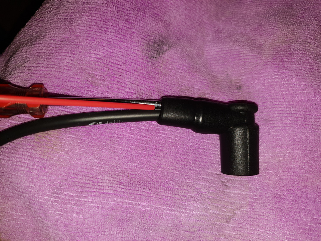


Bookmarks