

 Member
Wow, that looks really good for a breakout board! For the voltage regulator, I'd use the small (TO-92) version of the LM7805 (LM78L05, here: http://search.digikey.com/scripts/Dk...M78L05ACZFS-ND)
You need to consider carefully the power management of the system, unless you plan to only have it working with the car on, in which case it's an easy solution.
Thanks! That sounds like a good idea. I figured it would only be powered when the car is on, so I was leaning towards a straightforward regulator. I know it will generate heat but probably not too much, there is a lot of breathing room in the OBC shell from what I see. I am a big fan of switching power supplies because they are so efficient, but in the name of simplicity and my non-need for extended time powering of the unit with the engine off I decided to go this way.
Hmm, if I was engineering the unit I would have something listen to a button (i imagine you hold a button to enter this mode while the car is off?) and then have it trip a line HIGH or LOW (just opposite of normal) and also the physicality of the button down would start a 555 timer circuit which would power a switching transistor that connects the unit to a power source (parallell of course to the usual power source) so when the button is let go, the regular power that "woke up" the OBc and enacted the 555 timer circuit is gone but since the 555 timer circuit is started, the parallel power connection is maintained by the 555 circuit. For the duration of the 555 timer circuit, it would be saturating a switching transistor to deliver power to the OBC. Then you would have x amount of time to make your changes or see the time before the capacitance would run out and the 555 timer would de-saturate the switching transistor and it would disconnect the power line. If "x" time is not desired, and someone would want the unit to stay awake as long as changes are being made with no limit, a parallel connection could be made to every button which would energize the capacitor that is in charge of maintaining the 555 timer to stay awake so it never expires unless you don't press a button for a certain amount of time. Of course by applying voltage directly to the capacitor which is connected to pins on the 555 you would probably want a diode to prevent this button-triggered power from going INTO the pins on the 555 which initially charge the capacitor and thus only the capacitor would be charged and no other effects would be induced. The reason for the digital line HIGH/LOW differential is for the microcontroller to enable/disable certain functions which would not be available while entering this mode with the car off.The OEM OBC still allows functions like date and time to be accessed with the car OFF which brings up some pretty challenging power management issues.
I just ran that through my head again and realize if the buttons are parallel to charging the capacitor that keeps the 555 timer circuit on, then when you press the buttons for other reasons while the car is on, the HIGH/LOW swap would happen and would limit the functions of the OBC because the microcontroller would see the swap and act accordingly.. Oh well this was just my quick stab at solving that issue, not sure what kind of solution BMW actually came up with but that's probably what I would have done, along with something to solve the problem I just thought of. Possibly have the microcontroller watch voltage, 12.6V or less = battery, 12.7 or higher can be considered on because of the alternator (usually putting out 13.8). Or it could read the RPM data to see if the car is running and determine mode by that. Then the 555 timer circuit would just be providing the power unnecessarily while buttons are being pressed while the car is running but since it is a parallel connection to deliver the same power which is routed to it when it is on while the car is on, it wouldn't be making any difference unless the car was off and that connection wasn't already made. As new as I am to engineering I am full of ideas and that's how I learn so fast because i'm always testing ideas and exploring solutions and with experimentation and research I usually find out if they work or if they wouldn't, why they won't. it's a forever learning experience!
I'm working on some of the "bugs" and "oopses" of my original PCB design right now, I'll share my updated board after I finish it, and let you guys know how it goes once I produce, populate and test it.
Last edited by catatung; 04-17-2011 at 03:08 AM.
Member
I've just finished revising the board. Jumper settings are as follows:
JP1:
1-2 = Resistors to V+ (pull-up)
2-3 = Resistors to GND (pull-down)
NC = Pullup/down resistors not activated
JP2:
1-2 = Fix @1 to GND
2-3 = Fix @1 to V+
NC = Fix @1 NC
Power supply issues have been fixed, now the board expects 12V and delegates 12V to the 555 and 5v to the LCD. Thanks for telling me about the TO-92 package I did not even know there was one. I am only familiar with the TO-220 which I've used in so many projects. For example back in 1999 or so I had a car with no CD player so I took a cdrom that had a play button on the face and wired a 7812 and 7805 accordingly to power it, and powered the regulators by the 12V car voltage. I wired the audio out connector on the back (R G G L) to the aux input on the radio and voila, I had a CD player in my carI even got fancy in the future and found a 5 cd changer cdrom with play, rewind and ffwd buttons.
It will be a little while before I can produce and test this board but I will definitely keep you guys updated, if you see anything ambiguous at a glance or have any suggestions about it, let me know. The only thing left on my list of to-do is to see what pin #15 is for on the ribbon cable, because my 1st design, for some reason had the pullup resistors wired into it. It's time for bed though, I will do that tomorrow. It's already 6:30am!
Member
A popular approach is to put the MCU in full charge of power management, and then when there's nothing to do, have it power down the power hungry peripherals but continue running -- using just enough power and/or cycles to watch its inputs for renewed activity. In effect, you shift more or all of the power management into software, which I happen to favor because I'm a lot slower developing printed circuit boards.Originally Posted by catatung

If you go that route, you might consider the LP2950-5.0 instead of a 78L05 to reduce the quiescent current while the MCU is waiting for more activity. The LP2950 has a much lower drop out voltage, but requires a larger output capacitor (up to 2.2 uF instead of 10nF).
Last edited by johnf; 04-17-2011 at 01:19 PM.
Member
I second that! toner transfer takes time and practice, and I can definitely write code quicker than I can bang one of those outA popular approach is to put the MCU in full charge of power management, and then when there's nothing to do, have it power down the power hungry peripherals but continue running -- using just enough power and/or cycles to watch its inputs for renewed activity. In effect, you shift more or all of the power management into software, which I happen to favor because I'm a lot slower developing printed circuit boards.
Thanks for the info, I will save that for a V3 board though, I'm trying to keep this board as simple as I can and single sided since I am producing them at home.. And also if there is a bug it will be easier to track on just one side. But maybe if I get crazy in the future I will look into thisIf you go that route, you might consider the LP2950-5.0 instead of a 78L05 to reduce the quiescent current while the MCU is waiting for more activity. The LP2950 has a much lower drop out voltage, but requires a larger output capacitor (up to 2.2 uF instead of 10nF).
Member
If you provide a couple spots for 0.1 inch lead spacing electrolytic capacitors, one to the regulator input and one to its output, you can accomodate pretty much any standard and LDO regulator with whatever capacitors it may need, be they ceramic, film, tantalum or whatever.
I have had better luck making boards using laser printed transparencies and photoresistive boards. When I was a graduate student, I just used an overhead projector to expose them.
I've attached a screen shot of a board I worked on this weekend, and the previous one, and previous one, ad infinitum. It's a double-sided power supply and interface board that drives some Lavet clock motors.
I'll send the gerbers off to pcbwing.com who currently will make up to four boards (less than 100mm x 100mm) for about $50 including shipping.
Member
That's a good idea, anything that makes a board more versatile is a plus.If you provide a couple spots for 0.1 inch lead spacing electrolytic capacitors, one to the regulator input and one to its output, you can accomodate pretty much any standard and LDO regulator with whatever capacitors it may need, be they ceramic, film, tantalum or whatever.
I've seen some results of photoresistive boards and I like the idea. I saw a video of a guy who modified an oldschool HP flatbed scanner (probably a 5P or something like that, they were common back in the day) and hooked it up with lamps for UV exposure. I thought that was a nice touch for a DIY concept.I have had better luck making boards using laser printed transparencies and photoresistive boards. When I was a graduate student, I just used an overhead projector to expose them.
That looks really nice, I see you only had to have a couple of connections on the top of the board. I like the single sided best because you can clearly see where everything is going at one glance, but sometimes you just need to do some things on another layer. Also ground planes is one more thing I did not set up, I may do that on the final board.I've attached a screen shot of a board I worked on this weekend, and the previous one, and previous one, ad infinitum. It's a double-sided power supply and interface board that drives some Lavet clock motors.
That's not bad at all, once I produce a board that works well I may do that to get a professionally made board to use and then donate the other 3 on here to whoever may need them or want to play with them. Definitely not going to happen overnight but once I have everything working well it's a good possibility. MrGoodVibes is sending me an oscilloscope which I will be able to use to verify my 100Khz square wave circuit is performing correctly, which will be a big part in my testing the board. I wanted the square wave generated onboard as close to the LCD as possible, which means for less wires to connect and less chance for any kind of interference from the square wave to the LCD's pin 11.I'll send the gerbers off to pcbwing.com who currently will make up to four boards (less than 100mm x 100mm) for about $50 including shipping.
OBC hacker
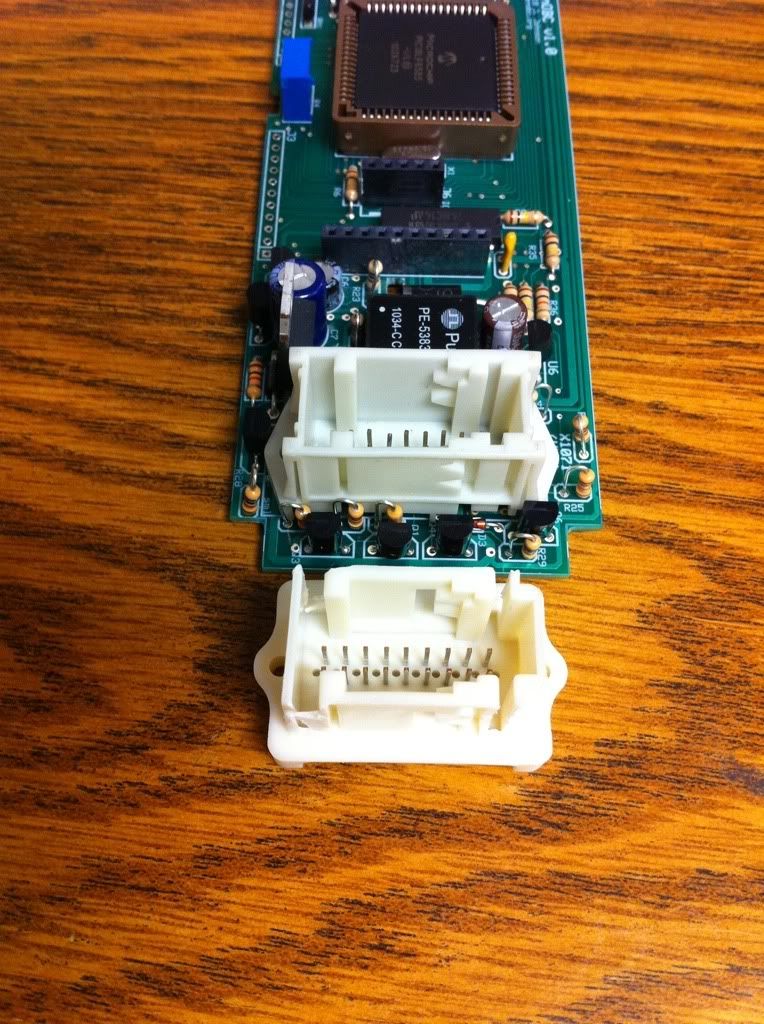
Ok so I got some stuff from JoyLove in the mail yesterday. Good news is there is a match for the X1071, but the bad news is it's a bit wide and won't fit in the stock OBC back cover:
I was able to hack off the "ears" with some flush cutters, and it does fit after that. I may just sand these down on a belt sander and use them if we can't find an alternative. It's still easier than desoldering the OEM X1071 connector.
1999 ///M3 TiAg | Heated Power Vaders | DDM Projector36 5000K 55W HIDs | DDM 3000K 35W HID Fogs
DDM Smoked Corners | DDM Weighted Shift Knob | K&N CAI | Mishimoto AL Rad w/Zionsville AL Shroud
Stewart HiPo Water Pump | Samco Hose Kit | 16" SPAL Puller Fan | Viper 5701LE Security
E36 OBC is now open! Join the effort: BF.C Thread | openOBC Wiki
Member
Is it the flange on the long edge that need to come off or the sightly wider keys at the ends?
E36 DICE MediaBridge BT and iPod support Photo location of the cabrio drain holes. Custom heated seats and lumbar support retrofit. Glovebox charging sockets and cupholders. E36 PDF Schematics UK Aftermarket E36 OBC bulbs Convert rear lights from non check-control to check-control DIY BMW E36 MFSW retrofit pictoral DIY All BMWs UK cheaper source for electrical connectors, Farnell, RS BMW INPA success E46/E39 onwards E36 vert mood lighting DIY BMW E36 puddle light and inner handle illumination DIY. E36 convertible flat bungee tension strap fix DIY BMW E36 PDF manualBMW E36 vert water in motor of tonneau area fix.
OBC hacker
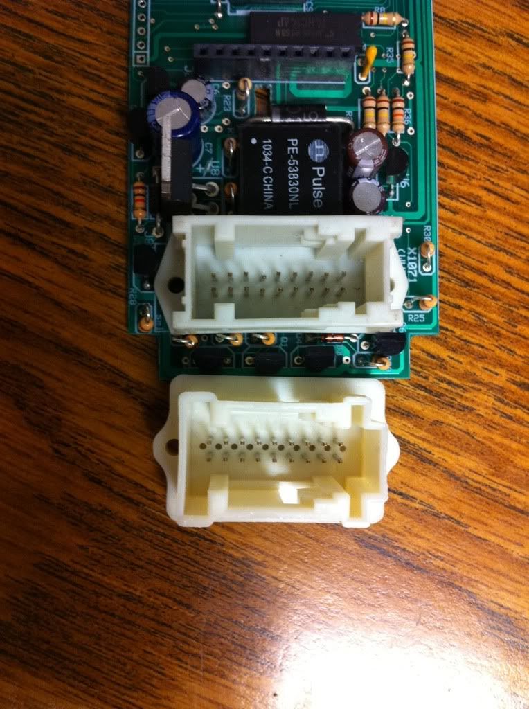
It's the ears on the top and bottom in the picture above. Here's how they look when trimmed enough to fit into the stock housing:
1999 ///M3 TiAg | Heated Power Vaders | DDM Projector36 5000K 55W HIDs | DDM 3000K 35W HID Fogs
DDM Smoked Corners | DDM Weighted Shift Knob | K&N CAI | Mishimoto AL Rad w/Zionsville AL Shroud
Stewart HiPo Water Pump | Samco Hose Kit | 16" SPAL Puller Fan | Viper 5701LE Security
E36 OBC is now open! Join the effort: BF.C Thread | openOBC Wiki
1.68G
So where exactly are you buying the connectors? I would like to but some so my prototypes aren't so pathetic.
Thanks-alan
Member
From RS and Farnell
E36 DICE MediaBridge BT and iPod support Photo location of the cabrio drain holes. Custom heated seats and lumbar support retrofit. Glovebox charging sockets and cupholders. E36 PDF Schematics UK Aftermarket E36 OBC bulbs Convert rear lights from non check-control to check-control DIY BMW E36 MFSW retrofit pictoral DIY All BMWs UK cheaper source for electrical connectors, Farnell, RS BMW INPA success E46/E39 onwards E36 vert mood lighting DIY BMW E36 puddle light and inner handle illumination DIY. E36 convertible flat bungee tension strap fix DIY BMW E36 PDF manualBMW E36 vert water in motor of tonneau area fix.
Member
KiwiJochen (of Navcoder) has just reverse engineered the coolant temp on the OBD1 data bus and possibly the oil temp too. This data bus is present at the OBC. Maybe he will share if you ask him nicely to get you going?
E36 DICE MediaBridge BT and iPod support Photo location of the cabrio drain holes. Custom heated seats and lumbar support retrofit. Glovebox charging sockets and cupholders. E36 PDF Schematics UK Aftermarket E36 OBC bulbs Convert rear lights from non check-control to check-control DIY BMW E36 MFSW retrofit pictoral DIY All BMWs UK cheaper source for electrical connectors, Farnell, RS BMW INPA success E46/E39 onwards E36 vert mood lighting DIY BMW E36 puddle light and inner handle illumination DIY. E36 convertible flat bungee tension strap fix DIY BMW E36 PDF manualBMW E36 vert water in motor of tonneau area fix.
Member
Hi all, my problem is slightly different from the topic, but will ask. I try to emulate the CCM, but for now without success. I use Tiny26 for software SPI, connected to pin 3,4,5 of X1070. Which bit obc recognize that there hooked ccm?
0 coolant or brake circuit
A coolant or brake circuit
2 low beam
3 license
4 tail
5 right brake
6 left brake
7 pulldown
What is "7 pulldown " bit? Can anyone who has recorded signal from ccm, to show it?
Sorry for my bad English, I'm from Bulgaria.
Best Regards
Member
I would understand "pulldown" as bit 7 always being low or 0.
The last time I designed something with a 4021 was in 1982. It's been a few years.
OBC hacker
Thanks for the advice! I just emailed Jochen; hopefully he can help with this aspect as I have not touched it yet. I'm using the hardware level shifter designed by benemorious, but have been unable to verify it myself.
1999 ///M3 TiAg | Heated Power Vaders | DDM Projector36 5000K 55W HIDs | DDM 3000K 35W HID Fogs
DDM Smoked Corners | DDM Weighted Shift Knob | K&N CAI | Mishimoto AL Rad w/Zionsville AL Shroud
Stewart HiPo Water Pump | Samco Hose Kit | 16" SPAL Puller Fan | Viper 5701LE Security
E36 OBC is now open! Join the effort: BF.C Thread | openOBC Wiki
Member
Hello ;-)
Some help: DME device address = 0x18
Member
So the signal should be something like this
but still the message is "Check control inactive"
OBC hacker
Are you letting the OBC do the clocking? It appears to be the master in the original design.
"check control inactive" may be due to improper pull up/down on the ccm lines.
1999 ///M3 TiAg | Heated Power Vaders | DDM Projector36 5000K 55W HIDs | DDM 3000K 35W HID Fogs
DDM Smoked Corners | DDM Weighted Shift Knob | K&N CAI | Mishimoto AL Rad w/Zionsville AL Shroud
Stewart HiPo Water Pump | Samco Hose Kit | 16" SPAL Puller Fan | Viper 5701LE Security
E36 OBC is now open! Join the effort: BF.C Thread | openOBC Wiki
Member
clock and latch come from obc, data returned from ccm.
Member
Already got a "Check OK". This is the right signal:
and this is the message "Washer fluid low":
first is bit7
bit 7 1 Brake Light Fail
bit 6 1 Brake Light Fail
bit 5 Tail Light Failure
bit 4 Lic Plate Light Fail
bit 3 Low Beam
bit 2 Coolant level
bit 1 Washer Fluid
bit 0 Pulldown
bit7 & bit6 = Brake Lights Failure
bits 7,6,2,1 are Active Low
bits 5,4,3 are Active High
OBC hacker
Awesome work!
1999 ///M3 TiAg | Heated Power Vaders | DDM Projector36 5000K 55W HIDs | DDM 3000K 35W HID Fogs
DDM Smoked Corners | DDM Weighted Shift Knob | K&N CAI | Mishimoto AL Rad w/Zionsville AL Shroud
Stewart HiPo Water Pump | Samco Hose Kit | 16" SPAL Puller Fan | Viper 5701LE Security
E36 OBC is now open! Join the effort: BF.C Thread | openOBC Wiki
Member
Yes.
Someone got for what is einheit2?
I guess it is related to the ccm but it seems not.
I think einheit1 is this:
einheit 1
bit7 ???
bit6 consum- mpg, l/100
bit5 range - mls, km
bit4 speed - mls, km
bit3 ???
bit2 check or no check
bit1 temp - F, C
bit0 clock 12, 24h
Last edited by veskobx; 05-02-2011 at 04:16 AM.
Member
Nice job of deciphering!
Some of the EINHEIT bits must choose the correct, fuel consumption calculation for the installed motor.
OBC hacker
Great work, I love all the reverse engineering going on in this thread!
An update from me: I've been conversing with Jochen (NavCoder) by email all week, trying to nail down the D-bus interface.
So far I tried:
a) An EDIABAS interface I got on eBay, connected to the round diagnostic plug under the hood, and
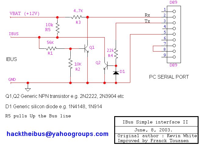
b) The "simple interface" i-bus circuit:
However both aren't allowing NavCoder to talk to any modules. I've double-checked my circuit for b) and it appears to be 100% correct.
I connected b) to X1071 Pin 5 (Diag TXD) which is supposed to go to diag port pin 20.
Any ideas?
1999 ///M3 TiAg | Heated Power Vaders | DDM Projector36 5000K 55W HIDs | DDM 3000K 35W HID Fogs
DDM Smoked Corners | DDM Weighted Shift Knob | K&N CAI | Mishimoto AL Rad w/Zionsville AL Shroud
Stewart HiPo Water Pump | Samco Hose Kit | 16" SPAL Puller Fan | Viper 5701LE Security
E36 OBC is now open! Join the effort: BF.C Thread | openOBC Wiki
Member
EDIABAS is the communications handler for the BMW suite of tools. It shares the com port to the programs INPA, NCS expert and WinKFP.
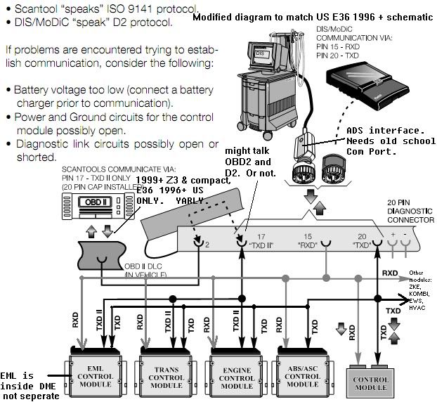
There are two data busses in a US E36. There is an OBD2 bus for the DME and EGS only. There is an OBD1 bus for everything.
The OBD2 bus is 1 wire, bi directional half duplex 10.4kBaud, and works with USB OBD2 scanners. The langauge spoken is ISO9141 aka K line aka KKL.
The OBD1 bus is a 2 wire, 9600 baud half (?) duplex system that requires a full COM port with DSR/DTR for TXD flow control in the adaptor. The language spoken is BMW propriety DS2 aka D2 aka ADS.
The ADS adaptor can be implemented on modern laptops via a PCMCIA-RS232 card, but must have a specific IRQ and hex address in BIOS that make it look like a COM1 on an old school MoBo for EDIABAS to accept it.
The OBD1 bus is connected to the OBC. I recommend you spend your efforts on this bus.
Attached is a file (in German) that shows what the ADS interface does. there is a rather nice block diagram showing DTR and hence why you cannot use ADS over USB-RS232.
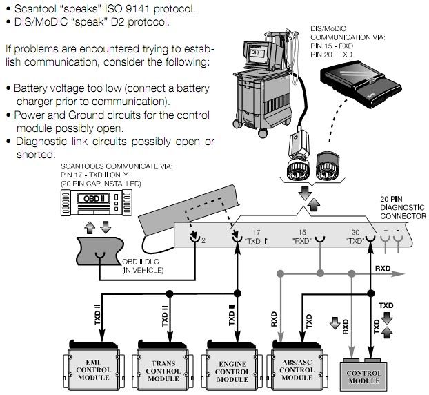
Here is another diagram from a BMW document, only for US models, that has some mistakes. It does however show a pair of independent buses. The tiny OBD2 and the big DS2 one.
I have corrected it in line with the schematic.
Last edited by Joylove; 05-04-2011 at 04:17 AM.
E36 DICE MediaBridge BT and iPod support Photo location of the cabrio drain holes. Custom heated seats and lumbar support retrofit. Glovebox charging sockets and cupholders. E36 PDF Schematics UK Aftermarket E36 OBC bulbs Convert rear lights from non check-control to check-control DIY BMW E36 MFSW retrofit pictoral DIY All BMWs UK cheaper source for electrical connectors, Farnell, RS BMW INPA success E46/E39 onwards E36 vert mood lighting DIY BMW E36 puddle light and inner handle illumination DIY. E36 convertible flat bungee tension strap fix DIY BMW E36 PDF manualBMW E36 vert water in motor of tonneau area fix.
 Posting Permissions


 Reply With Quote
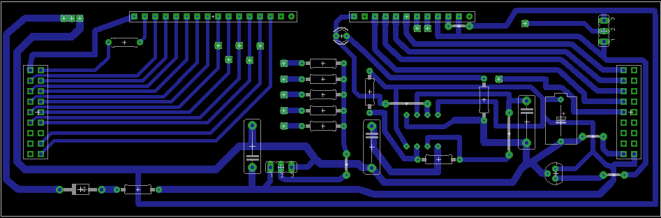


Bookmarks