

 OBC hacker
Yes that pinout is correct, however the LCD bias works fine at +5V and the LCD itself runs without problems at 3.3V.Originally Posted by catatung

If you look at my latest design posted a couple days ago, there is a full UART serial port exposed on 2 of the expansion pins. You could jump some wires between those and the other expansion pins that are tied to the spare X107n pins, and get RS-232 to the outside world.
I ran out of I/O pins on my mbed MCU board, so I chose to string a pair of I2C I/O expanders on the I2C bus to get the pins I needed.
I'm about 75% done with the new PCB layout using the mbed; I'll post here as soon as it's finished!
1999 ///M3 TiAg | Heated Power Vaders | DDM Projector36 5000K 55W HIDs | DDM 3000K 35W HID Fogs
DDM Smoked Corners | DDM Weighted Shift Knob | K&N CAI | Mishimoto AL Rad w/Zionsville AL Shroud
Stewart HiPo Water Pump | Samco Hose Kit | 16" SPAL Puller Fan | Viper 5701LE Security
E36 OBC is now open! Join the effort: BF.C Thread | openOBC Wiki
Member
Thanks for taking the time to explain your findings. I'm trying to set up the LCD to run off of an Arduino using the SPI library as found at http://www.arduino.cc/playground/Code/Spi.
As I understand it connections would be as follows:
---
1 +5 - power for the OBC LCD controller, can be 3.3v
2 gnd - ground
3 LCD bias (+6, works with +5) - power for the LCD
4 fix at 1 - tie this to +5 for TEXT and to gnd for ICONS
5 config strobe - ?
6 data strobe - ?
7 clock - ?
8 data - data is written to the LCD controller on this pin
9 final strobe - ?
10 enable - This connects to the Slave Select pin on the SPI controller
11 LCD clk - This needs to be connected to a PWM output - 20us period, 10us pulse width, 50% duty cycle
The only questions I have left are:
* pin 7 = clock - does this have to do with the 4 digit clock segment of the display or something to do with the "clock" frequency of the LCD controller?
* pins 5,6,9 - I am unsure what these pins would connect to? Must they be to digital pins on an SPI controller or do they need a specific signal during writing of data or ?
* I'm guessing the 100Khz refresh signal is written to pin 9? Or is that written to pin 8 after the command/data has been written?
* as far as the enable pin; in order to save pins on the arduino can I leave this hard-wired HIGH since there are no other SPI devices in my circuit? Or is there moments in time during communication when this must be brought low momentarily?
Thanks for all the help so far. Did you set up a donation page yet? I remember it was mentioned quite a few pages ago but don't remember seeing any definitive mention of it having been done.
OBC hacker
See my comments below in RED:
No problem! The donation link is at the bottom of this page: http://www.openobc.org/wiki/tiki-index.php
Last edited by m2pc; 03-15-2011 at 12:26 PM.
1999 ///M3 TiAg | Heated Power Vaders | DDM Projector36 5000K 55W HIDs | DDM 3000K 35W HID Fogs
DDM Smoked Corners | DDM Weighted Shift Knob | K&N CAI | Mishimoto AL Rad w/Zionsville AL Shroud
Stewart HiPo Water Pump | Samco Hose Kit | 16" SPAL Puller Fan | Viper 5701LE Security
E36 OBC is now open! Join the effort: BF.C Thread | openOBC Wiki
EE
BMW CCA Member
I'd love to tie everything you've accomplished with my little project. The more displays the better!
I will say, I'm running an ATmega328 at 16Mhz and I do not think its enough. Once I added together all my code for speed, temp sensors, and accelerometer, the speed is not calculating right. Time in between the pulses must be less than when the ATmega328 can read because of the other duties.
Guess I'm going mBed on this as well.
OBC hacker
^^^ NICE!
The mbed is perfect for this. For road speed, I plan to tie it to one of the digital I/O pins set as an interrupt-triggered input, then have it increment a counter. Then using a "ticker" object set to a certain period, sample the counter, compute the road speed, and reset the counter.
FWIW the openOBC reference design has an external I2C, RS-232, and parallel outputs that would be perfect for driving a 2nd display. You could even have the steering wheel stalk switch control the external display if desired.
1999 ///M3 TiAg | Heated Power Vaders | DDM Projector36 5000K 55W HIDs | DDM 3000K 35W HID Fogs
DDM Smoked Corners | DDM Weighted Shift Knob | K&N CAI | Mishimoto AL Rad w/Zionsville AL Shroud
Stewart HiPo Water Pump | Samco Hose Kit | 16" SPAL Puller Fan | Viper 5701LE Security
E36 OBC is now open! Join the effort: BF.C Thread | openOBC Wiki
EE
BMW CCA Member
Thats what I'm using.Code:if (secs == nsecs) { timem++; secs = nsecs ++; } if (timem == 1) { (RPM / 4712); MPH = (RPM); timem = 0; RPM = 0.0; } secs = millis() / 1000; buttonState = digitalRead(buttonPin); if (buttonState != lastButtonState) { if (buttonState == HIGH) { digitalWrite(7,HIGH); RPM++; } } lastButtonState = buttonState; lcd.setCursor(13,0); lcd.print(MPH);
Not sure if its my problem or not.
OBC hacker
Is this code polling or is it driven by an interrupt? You should:
a) Do all fast operations (counter increments, etc) inside the interrupt routine
b) Do all slow operations (LCD updates, etc.) in a main loop.
Example (psuedocode):
Code:int lastSpeedInput = 1; unsigned long counter = 0; void isr () { // Called on pin state change if (speedInput != lastSpeedInput) { counter ++; lastSpeedInput = speedInput; } } void main () { while (1) { // Do math and LCD update here when needed } }
1999 ///M3 TiAg | Heated Power Vaders | DDM Projector36 5000K 55W HIDs | DDM 3000K 35W HID Fogs
DDM Smoked Corners | DDM Weighted Shift Knob | K&N CAI | Mishimoto AL Rad w/Zionsville AL Shroud
Stewart HiPo Water Pump | Samco Hose Kit | 16" SPAL Puller Fan | Viper 5701LE Security
E36 OBC is now open! Join the effort: BF.C Thread | openOBC Wiki
EE
BMW CCA Member
I'm going to mess around with it tonight. See if I can optimize it a bit more or use an external counter.
1.68G
Have you figured out a rough estimate as to what a conversion kit would cost?
OBC hacker
I have no idea yet, until the reference design board is proven. The parts alone will be at least $100 in single quantities. I am looking to have the boards stuffed by a pick-and-place operation, which should reduce the cost and labor involved.
1999 ///M3 TiAg | Heated Power Vaders | DDM Projector36 5000K 55W HIDs | DDM 3000K 35W HID Fogs
DDM Smoked Corners | DDM Weighted Shift Knob | K&N CAI | Mishimoto AL Rad w/Zionsville AL Shroud
Stewart HiPo Water Pump | Samco Hose Kit | 16" SPAL Puller Fan | Viper 5701LE Security
E36 OBC is now open! Join the effort: BF.C Thread | openOBC Wiki
Member
Thanks a lot for the clarification, this info will help me greatly to try and get the LCD working in my project. I was debating whether the timings are too important and precise to attempt controlling it from an Arduino and through outputs on a 74HC595 shift register. Maybe you have a word of advice based on experience or principal knowledge of how these work? Perhaps it would be more efficient to try and free up pins by running the keypad button matrix through inputs on a CD4021BE shift register instead and use the native pins on the Arduino for the SPI emulation. Any opinions?5 config strobe - I call this "icon strobe" in my design. It's a positive-edge trigger for the icon data. It goes high for 50us after each icon character is sent to the LCD.
6 data strobe - This goes high for 50us after all text or all icons are written to the display.
9 final strobe - This is used to "strobe" the entire display after all icons and data have been written.
I only have 2 questions left:
* Can I tie pin 5 (config strobe) to GND permanently if I am only using text and not going to use icons? This would help free up a pin.
* With the "final strobe" pin - What behavior does the LCD expect from this pin and when does it expect it? Does this get a 50us high pulse also once all of the data is completed writing? If so do you know why? I would assume the pin 6 data strobe going high for 50us after all text is written would trigger everything that needs to happen once the data is complete.
Thanks again for your help, I will be sending you a little something - I'm unemployed at the moment [which is why I have so much time to tinker with this] so it won't be an earth-moving amount, but I know every little bit helps and I appreciate you taking the time to explain to me what you've found and how to use the LCD.
Thanks again
If you're going to provide a solution where the purchaser does all of the component placing and soldering, don't forget to have a look at what components are on the OEM board that could be re-used to save cost. For example, there was a really nice heat sink for a TO-220 package on mine which I assume is on every one. It sure beats the small ones you can buy from Radio Shack for a few bucks.I have no idea yet, until the reference design board is proven. The parts alone will be at least $100 in single quantities. I am looking to have the boards stuffed by a pick-and-place operation, which should reduce the cost and labor involved.
Last edited by catatung; 03-16-2011 at 03:03 AM.
EE
BMW CCA Member
Defiantly going mBed now. Blew up my ATmega328 last night.
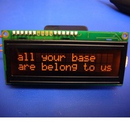
Also, m2pc, I've been looking for quite sometime for a higher quality LCD for my project. Do you know of any LCD that are actually amber on black like the factory BMW displays? All of these 16x2 claim amber on black (Like this one), but in reality, they are amber on... amber. The problem is, in bight sunlight, you cannot see them at all. Whereas the BMW LCDs do not have this problem.
I'm also trying to get better pixel density as well. 16x2 isn't really cutting it. Since I added the accelerometer, I need more screen realestate, but the space in the cluster is almost the perfect size for those 16x2s.
Last edited by Dricebrug; 03-16-2011 at 11:21 AM.
OBC hacker
The 74HC595 is one of my alltime favorite ICs. It's very easy to use (you can drive it with SPI btw) and easily cascadable. For relay driving, TI makes an equivalent, the TPIC6A596NE. It's a serial-to-parallel shift register with latch and high-current MOSFET drivers, all in one IC.
To save I/O pins in my design, I drive the keypad columns (5) using a CD4017 decade counter. This IC takes only a reset and clock input, freeing up 3 I/O lines for pennies. You could run the rows into a CD4021 shift register (the same one BMW chose for inside the check control module btw!) or my favorite, the 74HC165.
I have not tried this, but go ahead and report the results here!
The LCD doesn't refresh anything until this final strobe (I call it 'display strobe' in my design) transitions from low to high for 50us. Pulsing this line 'validates' all the previous icon and/or text data clocked in thus far.
Wow, I'm flattered! I know what it's like to be unemployed (I was for 9 months a couple years ago). I really appreciate any help that can be offered, but please donate only if it won't impact you or your family.
In order to provide the level of performance needed for the openOBC, I gutted the entire OEM board and built a new one. The only parts retained from the original PCB are the X1070 & X1071 connectors, until I can source these myself. JoyLove has a shipment of about half a dozen different 18-pin connectors and housings coming my way to evaluate.
Good luck and please post your findings in this thread!
Ouch!How'd that happen??
To achieve the look of the BMW factory LCDs, you need to find one with the polarizer reversed (or do it yourself). These are known as "inverse" LCDs in that they are black background with colored pixels, the opposite of traditional character LCDs.
Example:
http://www.sparkfun.com/products/9069
Last edited by m2pc; 03-16-2011 at 12:29 PM. Reason: Automerged Doublepost
1999 ///M3 TiAg | Heated Power Vaders | DDM Projector36 5000K 55W HIDs | DDM 3000K 35W HID Fogs
DDM Smoked Corners | DDM Weighted Shift Knob | K&N CAI | Mishimoto AL Rad w/Zionsville AL Shroud
Stewart HiPo Water Pump | Samco Hose Kit | 16" SPAL Puller Fan | Viper 5701LE Security
E36 OBC is now open! Join the effort: BF.C Thread | openOBC Wiki
Member
so what options are avail for those of us that have looked through and dont really have any idea in regards to whats being discussed but are interested in the additional obc functions?
OBC hacker
Well, it's really unlimited. I'm basically redesigning the OBC from the ground up, keeping the display and keypad. The plan is to copy all current OBC functions, but extend the functionality beyond the OEM version.
The details need to be ironed out; the first and foremost task is getting a PC board finalized that works. Once that is done, the real programming effort can begin.
I can tell you that there will be a USB port on the top of the OBC, behind the dash, that can be used to link to a PC or USB flash drive for data logging and interfacing with the vehicle data bus.
There's also an Ethernet network jack for connecting the OBC to a wired (or wireless via an adapter) network for remote access to the OBC's functions.
Also, there are 4 analog input signals on the new design that allow for connecting to a variety of sensors such as temperature (oil, water, transmission) and pressure (oil, boost/vacuum, fuel).
We are interfacing directly with BMW's D-bus (diagnostic bus) so we should have access to all modules in the car. Couple this with the USB and Ethernet ports, and the OBC becomes a "media bridge" between the car and the outside world such as a PC, smartphone, etc.
1999 ///M3 TiAg | Heated Power Vaders | DDM Projector36 5000K 55W HIDs | DDM 3000K 35W HID Fogs
DDM Smoked Corners | DDM Weighted Shift Knob | K&N CAI | Mishimoto AL Rad w/Zionsville AL Shroud
Stewart HiPo Water Pump | Samco Hose Kit | 16" SPAL Puller Fan | Viper 5701LE Security
E36 OBC is now open! Join the effort: BF.C Thread | openOBC Wiki
Member
Can I meekly request Bluetooth for wireless Serial Ports and hands free telephony?
E36 DICE MediaBridge BT and iPod support Photo location of the cabrio drain holes. Custom heated seats and lumbar support retrofit. Glovebox charging sockets and cupholders. E36 PDF Schematics UK Aftermarket E36 OBC bulbs Convert rear lights from non check-control to check-control DIY BMW E36 MFSW retrofit pictoral DIY All BMWs UK cheaper source for electrical connectors, Farnell, RS BMW INPA success E46/E39 onwards E36 vert mood lighting DIY BMW E36 puddle light and inner handle illumination DIY. E36 convertible flat bungee tension strap fix DIY BMW E36 PDF manualBMW E36 vert water in motor of tonneau area fix.
EE
BMW CCA Member
I have that exact LCD you posted. Garbage
Its really not amber on black. Its amber on darker amber.
Shifted or not it still cannot be seen in bright sunlight.
OBC hacker
http://mbed.org/users/peterbarrett19...roller-for-mb/
Done!
Hmm, maybe this will work, with the polarizer reversed?
http://www.modtronix.com/product_inf...roducts_id=333
Also, found a graphic LCD that has a viewing area of 60x18mm. Will that fit in the "mileage" spot in the cluster?
http://www.modtronix.com/product_inf...roducts_id=264
Last edited by m2pc; 03-16-2011 at 01:47 PM. Reason: Automerged Doublepost
1999 ///M3 TiAg | Heated Power Vaders | DDM Projector36 5000K 55W HIDs | DDM 3000K 35W HID Fogs
DDM Smoked Corners | DDM Weighted Shift Knob | K&N CAI | Mishimoto AL Rad w/Zionsville AL Shroud
Stewart HiPo Water Pump | Samco Hose Kit | 16" SPAL Puller Fan | Viper 5701LE Security
E36 OBC is now open! Join the effort: BF.C Thread | openOBC Wiki
Member
I'm just about ready to try hooking this up to my Arduino and write some code. Once I get it working I will let you know if leaving the CONFIG STROBE pin permanently to GND makes a difference of not.
Can you confirm that I have everything interpreted correctly? Here's my notes:
Code:Arduino SPI library: [http://www.arduino.cc/playground/Code/Spi] pin 13 SCK SPI clock pin 12 MISO SPI master in, slave out pin 11 MOSI SPI master out, slave in pin 10 SS SPI slave select Arduino - LCD physical wiring: LCD PIN ARDUNIO PIN LABEL Purpose 1 +5v/+3.3v +5v Power for the OBC LCD controller, can be 3.3v 2 GND GND GND 3 +5v LCD bias Power for the LCD (+6v, works with +5v) 4 GND GND GND 5 D4 Config Strobe High for 50us after each icon character is sent to the LCD - permanent to GND untested so far 6 D1 Data Strobe High for 50us after all text or all icons are written to the display. 7 D13 Clock High for 50us after each bit is set up. Connect to SCLK pin of the SPI controller. 8 D11 Data Connect this to the MOSI pin of the SPI bus. 9 D2 Final Strobe Used to "strobe" the entire display after all icons and data have been written. The LCD doesn't refresh anything until this transitions from low to high for 50us. 10 D3 Enable Pull low for 10uS and then leave high for normal LCD operation. Add 250ms wait after pulling it high before writing anything else to the LCD. 11 D9 LCD clk Connect to a PWM output - 20us period, 10us pulse width, 50% duty cycle. startup states: D4 [Config Strobe] OUTPUT, LOW D1 [Data Strobe] OUTPUT, LOW D2 [Final Strobe] OUTPUT, LOW D3 [Enable] OUTPUT, LOW Example software procedure to write to the LCD: 1 Refresh Signal D11 [LCD CLK] Generate PWM OUTPUT - 20us period, 10us pulse width, 50% duty cycle 2 Reset LCD D3 [Enable] Pull low for 10us, then lock at high 3 Write character bit D11 [Data] Write character bit data 3b ACK bit stage 1 D13 [Clock] High for 50us then back low 4 ACK Bit stage 2 D4 [Config Strobe] Pull high for 50us and then back to low - Permanent to GND untested at the moment 5 ACK Data Write D1 [Data Strobe] Goes high for 50us then back to low 6 Request Refresh D2 [Final Strobe] High for 50us and then back to low * note: when using an SPI driver library, 3b should be done automatically with the execution of step 3. * note: Steps 3 thru 4 can be repeated for additional characters/bits
Thanks again for all of your help!
Also, if you guys are looking for nice cheap LCD's for displaying information relating to your car, The old nokia 6100's have a nice colorful graphical screen which is SPI and can be used, have a look at http://optixx.org/2007/01/07/nokia-6100-lcd/ for some ideas.
Member
I think I may have found a hidden self-test mode for the OBC LCD display.
Have any of you ever triggered a mode that caused the OBC to cycle through what seems as every message it could possibly write on the screen in an endless loop? Even though it scrolls too fast to see what it's actually writing, I can confirm these are actual messages because whenever I upload code to my arduino the arduino stops running the code and the LCD hangs on the last message written for a moment before it clears out and I can clearly see it's a pre-set message, for example "INPUT TIME."
Heres a video --> [ame]http://www.youtube.com/watch?v=O7XSxcJ2poQ[/ame]
I forgot to ask before, is there a specific "language" or protocol to speak to the LCD driver with or can I simply write text values? In my code I just sent one value. I was not getting any response so I switched the final_strobe routine from LOW->50us->HIGH to HIGH->50us->LOW and the reaction I got was what you see in the video above. Perhaps triggering the reverse order causes this test mode to begin?
Also, you will see in the video, the brightness of the pixels are very dark. I know it's not the LCD itself because when I remove the 100Khz wire, I see the line that was refreshing at that moment gets corrupted but a bunch of pixels light up like they should be. Does this make any sense to you?
BTW I am using a 555 timer circuit to generate the 100Khz square wave. I figured this would free up a pin for my arduino.
The code I wrote is as follows:
Code:/* SPI library included with arduino v. 0022 states: pin 13 SPI clock SPI CLOCK pin 12 MISO SPI MASTER IN SLAVE OUT pin 11 MOSI SPI MASTER OUT SLAVE IN pin 10 SS SLAVE SELECT */ #include <SPI.h> int final_strobe = 2; int enable = 3; int config_strobe = 4; int data_strobe = 5; int ss = 10; int mosi = 11; int miso = 12; //unused but defined here anyway int clock = 13; void setup() { // set all pin modes (arduino defaults pins to INPUT if not defined otherwise) pinMode(final_strobe, OUTPUT); pinMode(enable, OUTPUT); pinMode(config_strobe, OUTPUT); pinMode(data_strobe, OUTPUT); pinMode(ss, OUTPUT); pinMode(mosi, OUTPUT); pinMode(miso, OUTPUT); pinMode(clock, OUTPUT); // set default pin states digitalWrite(final_strobe, LOW); digitalWrite(enable, HIGH); digitalWrite(config_strobe, LOW); digitalWrite(data_strobe, LOW); digitalWrite(clock, LOW); delayMicroseconds (1000000); // delay 1 second // begin SPI SPI.begin(); // pull enable low for 10us, then leave high for normal lcd operation digitalWrite (enable, LOW); delayMicroseconds (10); digitalWrite (enable, HIGH); // delay 1 second delayMicroseconds (1000000); } void loop() { // send some data on the mosi line SPI.transfer (255); // this should be done automatically by the SPI.transfer routine //digitalWrite (clock, LOW); //delayMicroseconds (200); //digitalWrite (clock, HIGH); //delayMicroseconds (50); //digitalWrite (clock, LOW); // pull config_strobe high for 50us then back to low digitalWrite (config_strobe, HIGH); delayMicroseconds (50); digitalWrite (config_strobe, LOW); // pull data_strobe high for 50us then back to low digitalWrite (data_strobe, HIGH); delayMicroseconds (50); digitalWrite (data_strobe, LOW); // pull final_strobe high for 50us, then back to low digitalWrite (final_strobe, LOW); delayMicroseconds (50); digitalWrite (final_strobe, HIGH); delayMicroseconds (5000000); // delay 5 seconds }
EE
BMW CCA Member
^^^
You have a unique taste is music.
M2pc, That second graphic LCD, ordered. Not sure how I did not come across that before. Most of these LCDs are all the same, and the only thing making them "Amber" or "green" is simply the LED backlight used. So, I will mess around with that to try to match amber.
Not having messed with a mbed, and I'm not sure what the best way to run this would be.
Last edited by Dricebrug; 03-18-2011 at 02:45 AM.
Member
haha, thanks Dricebrug. That's "The Streets" - a band from the UK. I live in the USA though. I like just about all kinds of music, though I might listen to certain types more often than others.. I just can't do opera.
I've added a SPI.setDataMode (SPI_MODE3); after the SPI.begin(); and all I can get is a row of 19 colons.
Still trying to figure this out, if anyone has any tips or sees something I'm doing wrong, I'm all ears!
Member
Also Dricebug, maybe have a look at the local junkyards for a nice LCD out of a BMW or other car.. LCDs designed specifically for a car's environment would be more likely to have the properties of sunlight resilience that you're looking for.
EE
BMW CCA Member
I was actually looking through all the BMW clusters for one that would have a suitable LCD. No dice except the newest cars with the center LCD.
I've ordered about 5 different LCD from different places. Hopefully one of them will have better sunlight resilience.
Now if only my damn mBed and boatload of MTmega328s would get here. Always have to have spares
OBC hacker
Funny you should mention this; Mefis (another member who's produced an openOBC board earlier in this thread) reported this phenomenon earlier but I didn't believe him; I guess this is confirmation then!
The strange part is when I first stuck the OBC on a logic analyzer to decode the data, I clearly saw the ASCII values for "INPUT TIME" being sent over the SPI interface, presumably going from the OEM OBC board -> display. I wonder if the OEM board triggered the display and the display send these values? Either way, I think it's best to just send all the text ourselves, since the openOBC is all about flexibility.
The OBC display is standard ASCII, with some funny exceptions. Example: a single quote mark (') is rendered as a tall, narrow "degree" symbol. To get a real single quote, you need to use a back-quote (`) which is rendered as (').
Dumb question, but I assume you have all the backlight lamps enabled, right? The only time I ran into this is when I had the contrast voltage too low or high.
It looks like a good start so far! Let us know if you get any further...
1999 ///M3 TiAg | Heated Power Vaders | DDM Projector36 5000K 55W HIDs | DDM 3000K 35W HID Fogs
DDM Smoked Corners | DDM Weighted Shift Knob | K&N CAI | Mishimoto AL Rad w/Zionsville AL Shroud
Stewart HiPo Water Pump | Samco Hose Kit | 16" SPAL Puller Fan | Viper 5701LE Security
E36 OBC is now open! Join the effort: BF.C Thread | openOBC Wiki
 Posting Permissions


 Reply With Quote


Bookmarks