

 License Revoked
Member
License Revoked
Member
wow banhammerOriginally Posted by louforenzi

OBC hacker
Haha classic! Looked like an automated bot or someone had their account hijacked.
1999 ///M3 TiAg | Heated Power Vaders | DDM Projector36 5000K 55W HIDs | DDM 3000K 35W HID Fogs
DDM Smoked Corners | DDM Weighted Shift Knob | K&N CAI | Mishimoto AL Rad w/Zionsville AL Shroud
Stewart HiPo Water Pump | Samco Hose Kit | 16" SPAL Puller Fan | Viper 5701LE Security
E36 OBC is now open! Join the effort: BF.C Thread | openOBC Wiki
Member
Folks:
What do you think about this circuit for the diagnostic connector. This should give us all the flexibility for 5 baud and 9600 baud on the UART. (SC16IS740 is a UART, with 16 bit arbitrary frequency divisor)
OBC hacker
Good idea on the UART, but where is the AG774 sourced? I couldn't find it anywhere...
For 9600 baud it would be trivial to "bit-bang" the serial via 2 I/O pins on the MCU. The PIC series has several pins that generate interrupts on change; you can use that to accurately time the bits and decode the RS-232 data.
1999 ///M3 TiAg | Heated Power Vaders | DDM Projector36 5000K 55W HIDs | DDM 3000K 35W HID Fogs
DDM Smoked Corners | DDM Weighted Shift Knob | K&N CAI | Mishimoto AL Rad w/Zionsville AL Shroud
Stewart HiPo Water Pump | Samco Hose Kit | 16" SPAL Puller Fan | Viper 5701LE Security
E36 OBC is now open! Join the effort: BF.C Thread | openOBC Wiki
Member
My mistake, there is a typo, the part is ADG774.
http://www.newark.com/jsp/search/bro...atchallpartial
OBC hacker
Ok, so this allows you to transmit on one or both lines of the ECU?
1999 ///M3 TiAg | Heated Power Vaders | DDM Projector36 5000K 55W HIDs | DDM 3000K 35W HID Fogs
DDM Smoked Corners | DDM Weighted Shift Knob | K&N CAI | Mishimoto AL Rad w/Zionsville AL Shroud
Stewart HiPo Water Pump | Samco Hose Kit | 16" SPAL Puller Fan | Viper 5701LE Security
E36 OBC is now open! Join the effort: BF.C Thread | openOBC Wiki
Member
Not exactly at the same time. That would be an either-or (analog multiplexer)
Reading the text bellow from http://www.hex.co.za/vaginfo/index.html
my impression was that you don't need to send the same signal in both lines.
Benemorius, it seems that you have the most experience, would you weight in? If we need to send the same data on both lines, or if we don't really know at this point, then maybe the safest thing for the first prototype I'm drawing may be to implement 4 analog switches each independenlty controlled, so we can set any combination on them (tx to K, rx to K, or tx to both and rx to L or K or any combination). This is doable, there is a similar UART with a few general purpose IOs.
"...Now that we've covered the basics, you should easily understand the following communication. This is an example of a log I've taken from entering the Engine Controller (address 01) of a VW Polo Classic. The only deviation from what I have described above, is the 5 bps initialization. It works as follows:
- the tester issues the 5 baud address of the controller it would like to initiate communication with.
- should the ECU recognize its address, it will reply with a sync byte (55), which is used by the tester to determine the baudrate that the ECU would like to communicate at.
- following a short delay, the ECU will send a Key word (consisting of 2 Key bytes, first the Least Significat Byte, followed by the MSB)
- the tester replies with the complement of the Key MSB byte. This hands master mode to the ECU, and it starts outputting the ECU info."
Member
This will be the circuit then. A full blown UART with GPIOs which control independent CMOS switches to steer the signal in any way needed....
Member
It certainly won't hurt to have the ability to transmit on both lines simultaneously, but I have no reason to believe that it's necessary. The ADS interface itself doesn't have that capability. I have mine working now and it's able to communicate with every module in my car.
OBC hacker
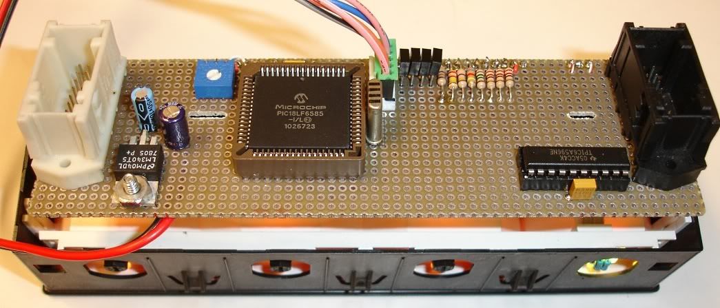
Update: I got my prototype board up and running with a new PIC chip, got the display interface worked out and the keypad is now fully readable:
I am clocking the LCD refresh (pin 11) using the PIC's hardware timer prescaled to ~100KHz
1999 ///M3 TiAg | Heated Power Vaders | DDM Projector36 5000K 55W HIDs | DDM 3000K 35W HID Fogs
DDM Smoked Corners | DDM Weighted Shift Knob | K&N CAI | Mishimoto AL Rad w/Zionsville AL Shroud
Stewart HiPo Water Pump | Samco Hose Kit | 16" SPAL Puller Fan | Viper 5701LE Security
E36 OBC is now open! Join the effort: BF.C Thread | openOBC Wiki
AA 55 AA 55 AA 55
This is cool stuff. Subscribed.
No PMs. Email through forum please.
BMW E36 Expert
That looks pretty trick!
1998 BMW M3 3.2 Cabrio Alpinweiß III on Schwarz German spec 1 of 12
SMG SRA PDC AUC OBC GSM HK UURS IHKA FGR MFL
IG: https://www.instagram.com/iflok/
Member
What about a 74HC4051 and lower base currents for a tenth the price?
Never mind, you switched to a 4066 in your next schematic. BTW, I bet you can get rid of the 2.2 ohm resistors if you like and use transmission gate's on resistance. It's three orders of magnitude greater and possibly even too much.
Last edited by johnf; 08-05-2010 at 10:31 AM.
Member
Yes... a generic part will do...
I switched to the generic CMOS switches just to give it maximum flexibility, and since the UART has external IOs is no problem to do it this way.
THe 2.2 are kiloohms, sorry about that typo. I was temptated to replace them with a nmos but the stock OBC has bipolar pulldowns and i am in the camp of maintaining the stock design as possible.
So the purpose of the 2.2K is to supply a reasonable current at the transistor base. We can use an NMOS and weld a wire in lieu of the resistor, but would hate to delete it now and have to go back to bipolar for whatever reason.
Member
A bipolar transistor is probably more robust.
------------------------------------------------------------------------
EDIT: I have been catching up on this thread.
If you need them, I can give you guys some rough limits on the 58g illumination signal (1070 pin 15) from measurements of 7 dimmer units.
Here are some measurements I took of the gong unit some years back.
If you are still curious about X1071 pin 14, I sorted out how to connect that aux. heating/ventilation signal to my IHKA and a Webasto Thermotop S system.
Out of curiosity, what sort of automotive transient protection do you plan to add?
Last edited by johnf; 08-05-2010 at 01:55 PM.
Member
Thanks for the input!
In terms of transient protection for the supply i do not have anything beyond what is build-in into the regulator. It is advertised as an automotive part. For signals, most have a diode (cathode to the remote pulldown) and in some cases a pair of diodes to VCC and ground (in the temp input for instance).
These are present in the stock OBC and i intend to use them as well in my drawing. Do you have any additional suggestions?
OBC hacker
Good ideas on the transient suppression mechanisms. The vehicle is one of the most noisy electrical environments, with many possible sources for interference, shorting, etc.
Today's update from me -- I have an M3 cluster and check control module on the bench and I'm getting the C code written to support those. Much better than having to sit in the hot car while decoding bits!
I was able to rig the cluster to power on and I can drive the fuel tank line with a potentiometer to see the resulting serial data stream. Did anyone confirm that the cluster responds on the TX and RX diag lines? If so, this may be a nice means to dial in the K/L line communications as well.
More to come!
1999 ///M3 TiAg | Heated Power Vaders | DDM Projector36 5000K 55W HIDs | DDM 3000K 35W HID Fogs
DDM Smoked Corners | DDM Weighted Shift Knob | K&N CAI | Mishimoto AL Rad w/Zionsville AL Shroud
Stewart HiPo Water Pump | Samco Hose Kit | 16" SPAL Puller Fan | Viper 5701LE Security
E36 OBC is now open! Join the effort: BF.C Thread | openOBC Wiki
Member
My cluster replies to {0xd, 0x0, 0x05, 0x00, 0x08} sent on RX at 9600 8e1. It will be interesting to see if yours does as well. I suspect we may need slightly different addresses and packet types for different years.
The first two bytes are the address. The third is the packet size. From the fourth byte up to the last byte is data. The last byte is a checksum of all previous bytes. Every module except the 3.3.1 DME seems to follow this, although some use only one address byte.
You might try a single-byte address of 0x80 if it doesn't reply to 0xd.
Has anyone tried running the LCD drivers at 3.3v or with 3.3v signals? It would be nice to avoid unnecessary parts if they don't appear to care.
Oh, well I guess I'll still need a 5v rail for USB. I suppose it isn't worth running the LCD out of spec just to save a few pullup resistors.
Last edited by benemorius; 08-06-2010 at 03:04 AM. Reason: Automerged Doublepost
Member
At the least, I might add 14VDC/18VAC varistors before the regulators to protect them beyond 43.5 and 60 Volts. Or perhaps a series resistor and clamping TVS/zener diode before your low current regulators, but it all depends on how unlikely you want to make a failure.
Can signal input transients raise the supply voltage because of the clamp diodes?
Last edited by johnf; 08-06-2010 at 07:05 AM.
Member
In theory a very large powerful transient would, but i would argue that the stock OBC as designed has standed up properly in my car for 10 long years and i do not see a lot of varistors and zeners in it.
Regardign the supply for the display, the logic may be fine but you need to bias the LCD with a reasonable voltage. 3.3 as LCD bias may be cutting your maximum contrast signifcantly.
I saw a ~6V on pin 3 if i am not mistaken, and I just tied it to +5. I presume this is for LCD biasing.
Last edited by Mefis; 08-06-2010 at 02:20 PM.
OBC hacker
Yes, pin 3 is for the LCD bias. I tied this to the center leg of a 10K pot with one side to ground and the other to +12V. I found that it needs to be slightly higher than +5V for the best contrast. A simple resistor divider would suffice for the production version.
1999 ///M3 TiAg | Heated Power Vaders | DDM Projector36 5000K 55W HIDs | DDM 3000K 35W HID Fogs
DDM Smoked Corners | DDM Weighted Shift Knob | K&N CAI | Mishimoto AL Rad w/Zionsville AL Shroud
Stewart HiPo Water Pump | Samco Hose Kit | 16" SPAL Puller Fan | Viper 5701LE Security
E36 OBC is now open! Join the effort: BF.C Thread | openOBC Wiki
Member
another comment on the transient suceptibility is that most inputs (except temp) are through a 82K/100K resistor divisor (acutally 130K/50K for 3.3) and the likelyhood of damage thorugh those resistors is also small.
Good point. That is missing in my drawing. Thanks!
Last edited by Mefis; 08-06-2010 at 02:31 PM. Reason: Automerged Doublepost
OBC hacker
Even at 60V, that's less than 1mA into a dead short (0.73mA [40mW]). If these are tied to an MCU input pin, which has a very high impedance anyway, the power dissipation should be close to zero.
I think the resistor divider is an inexpensive, reliable method for protecting these inputs. If we're really worried, we could put a diode in series with any inputs that are active low, so positive voltage couldn't even pass through.
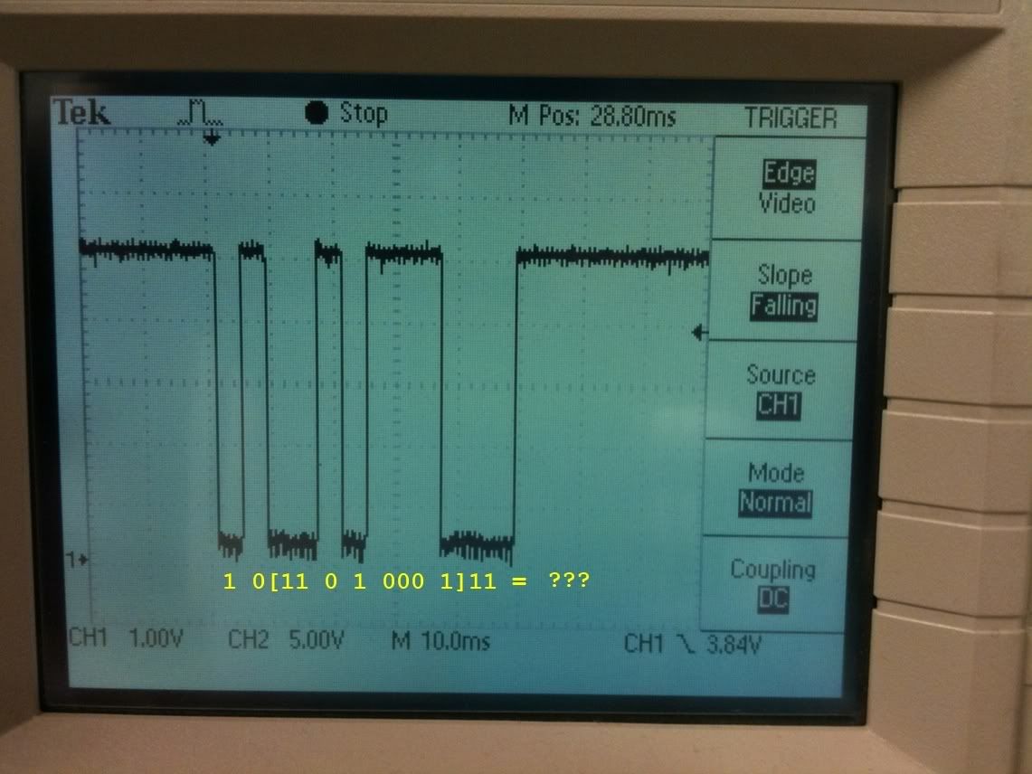
Back to the fuel tank level signal, Benemorious, I tied this to +5V with a 10K pullup, but I'm having a difficult time decoding the bits, particularly how to distinguish between a logic "1" and "0".
Are you sure this is 12 bits? Often times I could only count 10 or 11 bits visually on my scope, unless the last bit is the same as the "idle" state between transmissions.
Is this interpretation correct?

Last edited by m2pc; 08-06-2010 at 02:51 PM.
1999 ///M3 TiAg | Heated Power Vaders | DDM Projector36 5000K 55W HIDs | DDM 3000K 35W HID Fogs
DDM Smoked Corners | DDM Weighted Shift Knob | K&N CAI | Mishimoto AL Rad w/Zionsville AL Shroud
Stewart HiPo Water Pump | Samco Hose Kit | 16" SPAL Puller Fan | Viper 5701LE Security
E36 OBC is now open! Join the effort: BF.C Thread | openOBC Wiki
Member
As long as you guys have thought about it. I don't know all the specifics of your hardware or software, and it would take me a while to trace out the preliminary schematic.
Last edited by johnf; 08-06-2010 at 03:23 PM.
 Posting Permissions


 Reply With Quote
Bookmarks