

 is going slow.
example. asking to a Z3 cluster to identify himself...
Interface Trace of the job above.Code:VARIANTE = KOMBI36C OBJECT = KOMBI36C JOBNAME = IDENT SETS = 1 UBATT CURRENT = OFF UBATT HISTORY = ON IGNITION CURRENT = OFF IGNITION HISTORY = ON JOB STATUS = SET 1: RESULT 1: [ INTEGER ] ID_HW_NR = +6 RESULT 2: [ INTEGER ] ID_SW_NR = +11 RESULT 3: [ TEXT ] ID_BMW_NR = "7893280" RESULT 4: [ INTEGER ] ID_LIEF_NR = +10 RESULT 5: [ TEXT ] JOB_STATUS = "OKAY" RESULT 6: [ BINARY ] SG_ANTWORT = 18 Bytes, 000: 80 12 A0 F7 89 32 80 06 ...÷2.. 008: 03 90 00 16 02 10 11 03 ........ 010: 73 0E s. RESULT 7: [ INTEGER ] ID_DATUM_KW = +16 RESULT 8: [ INTEGER ] ID_BUS_INDEX = +0 RESULT 9: [ INTEGER ] ID_CAN_INDEX = +3 RESULT 10: [ INTEGER ] ID_COD_INDEX = +3 RESULT 11: [ TEXT ] ID_LIEF_TEXT = "VDO" RESULT 12: [ INTEGER ] ID_DATUM_JAHR = +2 RESULT 13: [ INTEGER ] ID_DIAG_INDEX = +90 RESULT 14: [ INTEGER ] ID_AENDERUNGSINDEX = +73
__________________________Code:_EDIC [ 124703] SENDECUTEL _EDIC [ 124703] INPUT: 80 04 00 _EDIC [ 124703] I -> D: 14 06 00 FF FF 00 _EDIC [ 124703] D -> I: 01 03 00 _EDIC [ 124703] I -> D: 13 04 00 01 _EDIC [ 124703] D -> I: 01 04 00 30 _EDIC [ 124703] I -> D: 06 06 00 80 04 00 _EDIC [ 124766] D -> I: 01 15 00 80 12 A0 F7 89 32 80 06 03 90 00 16 02 10 11 03 73 _EDIC 0E _EDIC [ 124766] I -> D: 13 04 00 01 _EDIC [ 124766] D -> I: 01 04 00 30 _EDIC [ 124766] ERROR: NO ERROR _EDIC [ 124766] OUTPUT: 80 12 A0 F7 89 32 80 06 03 90 00 16 02 10 11 03 73 0E
asking him to show engine rpm from CAN bus (z3 has CAN, well my E36 too but mine is frankenstein)
Trace.Code:VARIANTE = KOMBI36C OBJECT = KOMBI36C JOBNAME = STATUS_CAN_MOTORDREHZAHL_LESEN SETS = 1 UBATT CURRENT = OFF UBATT HISTORY = ON IGNITION CURRENT = OFF IGNITION HISTORY = ON JOB STATUS = SET 1: RESULT 1: [ TEXT ] JOB_STATUS = "OKAY" RESULT 2: [ BINARY ] SG_ANTWORT = 6 Bytes, 000: 80 06 A0 00 00 26 .....& RESULT 3: [ TEXT ] STAT_MOTORDREHZAHL_EINH = "U/min" RESULT 4: [ LONG ] STAT_MOTORDREHZAHL_WERT = +0
Code:_EDIC [ 443985] SENDECUTEL _EDIC [ 443985] INPUT: 80 09 06 0A 00 00 92 02 _EDIC [ 444000] I -> D: 14 06 00 FF FF 00 _EDIC [ 444000] D -> I: 01 03 00 _EDIC [ 444000] I -> D: 13 04 00 01 _EDIC [ 444000] D -> I: 01 04 00 30 _EDIC [ 444000] I -> D: 06 0B 00 80 09 06 0A 00 00 92 02 _EDIC [ 444047] D -> I: 01 09 00 80 06 A0 00 00 26 _EDIC [ 444047] I -> D: 13 04 00 01 _EDIC [ 444047] D -> I: 01 04 00 30 _EDIC [ 444047] ERROR: NO ERROR _EDIC [ 444047] OUTPUT: 80 06 A0 00 00 26
Last edited by nuvola rossa; 06-26-2010 at 04:56 AM.
Member
Do you have any photos of that? Putting the OBC in the center console might allow 318ti owners to add this OBC without making major alterations to the dash.Originally Posted by Squeak007

DON'T HATE THE HATCH!
From Page 68 of the 1997 318ti Owners Manual: "Vehicles equipped with ASC+T remain subject to the laws of physics."
Member
ill take some screen shots later today or tomorrow of the cad and post them so you can see what it will look like.
anyone know where i could get USB ports with a spring loaded cover?
Member
Well out of boredom and curiosity I decided to try installing ediabas/inpa just to see how far it would get in wine. Now that I've changed my pants, I've come back to report my findings. Not only did it install, and not only does it run, but it actually works!I scoped my serial port and can clearly see 9600 baud output on the TX pin, and I can get the battery and ignition indicators to come on by pulling up the DSR and RI pins. I'm still not sure what to do about the ADS interface and 5 baud transmissions, but it should be easy to wire up some level conversion to get this to talk to at least a few modules. I know they don't all require slow initialization.
Success! I can talk to the airbag and body electronics modules, which means my obc can too given some time. I need to make my circuit a little better and see what else I can find out. I assembled it in a hurry and it's clearly glitchy. It may be preventing communication with other modules.
Last edited by benemorius; 06-27-2010 at 12:15 PM. Reason: Automerged Doublepost
is going slow.
that's the easy part
you need a fully ADS interface diagram with BOM?
you'll go ahead faster now with ediabas. Use TOOL32, you can do single jobs with that and it's easy to trace.
PS: you'll have a lot of curiosity when you'll see NCS expert
Last edited by nuvola rossa; 06-27-2010 at 01:47 PM.
Member
Indeed! Do you have one? I couldn't find a thing.
Perhaps so, but it doesn't seem to run in wine. What's to be curious about?PS: you'll have a lot of curiosity when you'll see NCS expert
OBC hacker
Wow, amazing progress guys! For some reason I'm wasn't getting alerted with new posts in this thread, maybe I unsubscribed.
*subscribed for sure!*
I'm almost done with the OBC documentation, as well as fully documenting the X1070/1071 connectors on the back of the OBC.
Once that's done, I'll be bringing the website back online and posting everything I know.
On the hardware side, I fabricated a piece of fiberglass protoboard the same size as the OBC logic board;
I plan to install a PIC on that and get it working for prototype purposes.
It feels great to be part of this project, and to see all the doors opening up in front of us.
Props to all, keep up the good work!
1999 ///M3 TiAg | Heated Power Vaders | DDM Projector36 5000K 55W HIDs | DDM 3000K 35W HID Fogs
DDM Smoked Corners | DDM Weighted Shift Knob | K&N CAI | Mishimoto AL Rad w/Zionsville AL Shroud
Stewart HiPo Water Pump | Samco Hose Kit | 16" SPAL Puller Fan | Viper 5701LE Security
E36 OBC is now open! Join the effort: BF.C Thread | openOBC Wiki
Member
Haha! i wish i was a genius in electronics.
Keep up the good work guys!!
OBC hacker
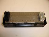
Snapped a few pics of what I'm working on:
LED OBC Backlight:
I desoldered X1070/1071 connectors on my board:
Prototype board with X1070/1071 mounted:
1999 ///M3 TiAg | Heated Power Vaders | DDM Projector36 5000K 55W HIDs | DDM 3000K 35W HID Fogs
DDM Smoked Corners | DDM Weighted Shift Knob | K&N CAI | Mishimoto AL Rad w/Zionsville AL Shroud
Stewart HiPo Water Pump | Samco Hose Kit | 16" SPAL Puller Fan | Viper 5701LE Security
E36 OBC is now open! Join the effort: BF.C Thread | openOBC Wiki
Member
anyone with a dead OBC they could send me ill have my dad who's a mechanical engineer and his friend who;s and electronical engineer figure this out.
Member
Contribution is always appreciated, but there's really nothing left to figure out on the factory OBC. At this point we need to be writing some interface code and possibly laying out a development PCB to let the software guys get in on the action if there's enough interest. Pretty soon we could start to see things moving very quickly if time and motivation remain in good supply. I have to admit though, with most of the fun parts behind us, I'm finding it more difficult to stay focused.
Member
That is correct, i think everything is figured out from the stock OBC, except for these opens:
-MPG line form the instrument cluster?
-Fuel level line?
And finally the check module. We know there is a simple shift register in there, but i do not have any more detail. If someone has a dead check module can they write me? How about a openOBC board in return?
Once i have that closed, i'll be finishing a drawing of a prototype board. My board will have the following items:
- copy exact of high current outputs for check light, backlight, etc.
- copy exact of keboard and screen.
- copy exact of ext. temp, fuel (?) and all other lines
- additional hi current outputs (i want radar light in the unused instrument bulb holes, m2pc wants color leds.
-GPS module
- 3 axis accelerometer chip. +- 6g
-bluetooth moule (serial port through bluetooth)
- flash microSD card (for location-aware radar det.)
- "daugther board" connector with general purpose A/D. just a header for everythign else to-be-determined, radar interface, etc.
any additional suggestions not mentioned before?
Great work Benemorious!
Is the circuit you posted the glitchy one? Are those TX and RX lines going to a MAX232 or something similar?
Last edited by Mefis; 06-29-2010 at 07:15 PM. Reason: Automerged Doublepost
Member
I have an input connected to the MPG wire. I just need to write some code for it and confirm how it works. Since the engine has to be running for that, I haven't gotten around to it yet. I'm not sure about fuel level.
Done quite some time ago. It can be queried more or less like this:And finally the check module. We know there is a simple shift register in there, but i do not have any more detail. If someone has a dead check module can they write me? How about a openOBC board in return?
The result is something like this:Code:int ccm_query() { int status = 0; pPIO->PIO_SODR = CCM_CLOCK; pPIO->PIO_SODR = CCM_LATCH; for(int i = 7; i >= 0; i--) { delayms(1); if(pPIO->PIO_PDSR & CCM_DATA) status += 1 << i; pPIO->PIO_CODR = CCM_CLOCK; delayms(1); pPIO->PIO_SODR = CCM_CLOCK; } pPIO->PIO_CODR = CCM_CLOCK | CCM_LATCH; return status; }
And it can be interfaced a bit like the schematic I've attached.CCM status: 0xe3
The circuit I posted is how my OBC is connected to the diagnostic bus. The glitchy one was how I interfaced a serial port to the diagnostic bus for ediabas, though it hardly looks any different. It was glitchy because the k line doesn't quite reach 12v at idle and it wasn't fully turning off a transistor. Nothing changed after correcting it, aside from fewer retransmissions. The TX and RX lines go straight to a microcontroller. I bend and break a lot of rules during reversing and prototyping. You could connect them to a max232 if you wanted to interface to a serial port. I chose to remove the PNP transistors and go straight to the serial port as I don't keep any max232 around in DIP.Great work Benemorious!
Is the circuit you posted the glitchy one? Are those TX and RX lines going to a MAX232 or something similar?
Member
Well i am going to draw my prototype according to your schematic (thanks), but I am not clear. The K line was not quire reaching 12V so you corrected? by reducing the pullup resistor value? What is the value that works best for you?
And then you have a resistor in series to your logic? Then i guess you go to some NPN base to interface to your 3.3V logic?
OBC hacker
For high current outputs, let's use something like ULN2803 which has 500mA per channel with logic-level inputs.
They even have reverse feedback diodes built in, perfect for direct driving relays & solenoids.
1999 ///M3 TiAg | Heated Power Vaders | DDM Projector36 5000K 55W HIDs | DDM 3000K 35W HID Fogs
DDM Smoked Corners | DDM Weighted Shift Knob | K&N CAI | Mishimoto AL Rad w/Zionsville AL Shroud
Stewart HiPo Water Pump | Samco Hose Kit | 16" SPAL Puller Fan | Viper 5701LE Security
E36 OBC is now open! Join the effort: BF.C Thread | openOBC Wiki
Member
The stock OBC has actually N-FET 2A rated driven by logic level. Is possible that they avoided bipolar because of the increased EM noise immunity. I would like to go along with those wise Siemens engineers.
Member
In that case I apologize for being brief. I have a hard-coded -vvv switch so I try to keep my verbosity in check where possible. I'll make an effort to bring my OBC inside soon and make a more complete schematic of it. Perhaps tonight.
In the mean time, a direct answer to your two questions:
The significance of the k line not idling quite at 12v was simply that it was insufficient to turn off a PNP transistor with the emitter on the 12v rail. Moving it to a 3.3v rail solved this oversight. The k and l line pullups will need to be somewhere between 470 and 2k2. I haven't yet determined what is safe or necessary, but it will lie between those values. What you see in that schematic is what goes directly to the microcontroller. As you've pointed out, this isn't an acceptable thing to do to a 3v3 logic gate in a production device. I'm just making use of the internal clamping diodes. They won't see any use in the finished design, so I'm making sure they don't feel left out.
Member
This is how my breadboard looks right now to the best of my knowledge, excluding perhaps some resistors that are still "safely" too high. Pins marked "IO" belong to a microcontroller.
I haven't driven to test the speed input, and I haven't fueled up to test the fuel level input. I'm presently assuming that pin 9 in X1071 (white) is fuel level. Mine reads 0.3v right now and it's empty enough that I'll probably be putting some fuel in it before I go to put fuel in it.
I don't know how to drive the chime and independent ventilation outputs as I have neither.
Illumination is a PWM signal. High current I assume.
Pin 15 in X1070 appears to be a 96Hz clock signal coming from (presumably) the instrument panel. It never changes as long as the ignition is on. Thoughts anyone?
Fuel consumption does appear to be delivered as an injector trace. It will make an acceptable source for RPM too.
I haven't identified pin 3 in X1071. Mine is at 12v with the ignition on.
Member
X1070 pin 15 is the intensity of natural light inside of the car - this signal comes from the sensor in the instrument cluster. (this is again my understanding and I may be wrong)
X1071 pin 9 is the fuel tank level signal, coming from the instrument cluster
X1071 pin 6 is the fuel consumption (injector) signal, not from the instrument cluster but consumed by it as well as by the OBC.
For using EDIABAS and any GUI on tp of it (INPA, DIS...), you need ADS interface and a real COM port for cars up to model year around 1994. For never cars, OBD interface with a COM/USB adapter is enough. Neither ADS nor OBD interfaces are expensive or unavailable at this point.
Sorry for answering so late, I was not getting any new post notifications until now.
is going slow.
...
Last edited by nuvola rossa; 06-30-2010 at 08:41 AM. Reason: wrong information
Member
AFAIK, dimmer is pin 16. Pin 15 is what I said.
is going slow.
x1070 pin 15 goes to cluster x17 pin 24 in my book.
x17 pin 24 is dimmer output signal brightness/information signal for connected control modules and goes to OBC or multifunction clock.
this from bmw etm.
x1070 pin 16 is from dimmer.
well you're right. I made confusion cause it calls "dimmer" the other too.
sorry.

Member
Is cool. X1070 pin 16 feeds the keyboard backlight so it makes sense that pin 15 would be this natural light signal. Perhaps benemorious can confirm that the frequency changes by natural light. In that case it should be a simple MCU timer pin
What about pin 3 on X1071? Not connected to the car in my MY99 M3, but it goes to body computer in earlier MYs? I see it has a high power output just like the one for the blower relay.
Any thought on what it does to those <97 folks?
Last edited by Mefis; 06-30-2010 at 09:05 AM. Reason: Automerged Doublepost
Member
X1071 pin 3 is a bit of a riddle but my guess is that the OBC can set off the alarm by grounding this pin.
Here is why:
On production years up to 93 and in 95 this is connected to "OBC horn relay"
In 94 it is a "data link" to the ZKE pin 16.
On later years, ZKE pin 16 is connected to the alarm module...
Last edited by jarda; 06-30-2010 at 09:43 AM.
OBC hacker
True, but 2A is way overkill for driving a relay or lamp.I've been using these driver ICs for several recent projects, and I love them!
Hmm, interesting find. I have this pin also marked "N/C" since I didn't find a wire going to it from my car's harness.
I wonder if the "CODE" function is able to set off the alarm when the wrong code is entered more than a few times?
Also, it makes sense that the "dimmer" input is PWM -- it's a signal generated by the dash light level knob under the steering wheel.
The other input is used to adjust the brightness of the instruments and OBC from the light sensor in the cluster.
Likely this is done by the OBC using PWM on the 2 MOSFETs that control the clock and main display/keypad backlights.
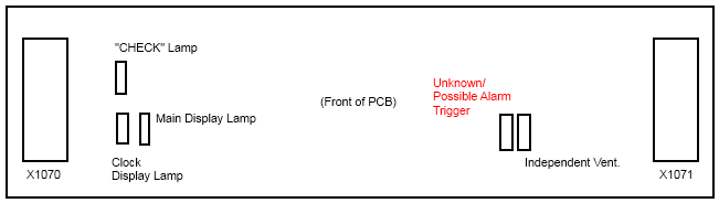
I traced out the 5 power MOSFETs on the PCB and came up with the following diagram:
Also, I updated my OBC external connections diagram:

Last edited by m2pc; 06-30-2010 at 11:58 AM. Reason: Automerged Doublepost
1999 ///M3 TiAg | Heated Power Vaders | DDM Projector36 5000K 55W HIDs | DDM 3000K 35W HID Fogs
DDM Smoked Corners | DDM Weighted Shift Knob | K&N CAI | Mishimoto AL Rad w/Zionsville AL Shroud
Stewart HiPo Water Pump | Samco Hose Kit | 16" SPAL Puller Fan | Viper 5701LE Security
E36 OBC is now open! Join the effort: BF.C Thread | openOBC Wiki
 Posting Permissions


 Reply With Quote


Bookmarks