
 Member
This thread is outdated... The one-touch turn signal (OTTS) module is currently at its third generation with many improvements over the first version described in this thread. The newer versions are built around a microcontroller and new features include exact blink count, comfort mode canceling and full flash functionality. The third generation uses solid-state components instead of relays for reliable and silent operation. The latest version is also compatible with more different makes of cars. For a complete write-up including diagrams and source code, read the one-touch turn signal module article at E31Wiki.org.
One-touch turn signal module - version 3.0
[posted to multiple E31 communities]
One-touch turn signal modification (version 1.0 - OUTDATED - NO LONGER RECOMMENDED TO BUILD - UNSUPPORTED)
I think everyone knows a one-touch turn signal although you may know it under a different name. Its function is simple: You tap the turn signal lever and without holding it the blinkers will blink three times. I always thought of this feature as a stupid gimmick until my last two cars both came equipped with a one-touch turn signal. I noticed I began using the feature more and more often when changing lanes. The gimmick became a habit and I caught myself sometimes tapping the turn signal lever - expecting it will blink a few times - in cars that don't have this feature. The E31 is one of them...
While browsing the Internet I came along a few hardware solutions to add the one-touch turn signal functionality to a car, but none of the solutions could satisfy me. They were too expensive for such a simple device and/or equipped with other useless stuff I don't want. Besides, between the lines of what's possible, I prefer to develop and build things like this myself.
The idea
The most simple approach to implementing a one-touch turn signal is a device that simulates the turn signal lever when it receives a tap from the real lever. The device has to comply to a few basic rules to make sure no unwanted situations occur:
- The blink timer should start immediatly when activating the turn signal lever - not when releasing it. If the blink time is say 3 seconds and you tap the lever for one instance, the blinkers should flash 3 seconds, but when you hold the lever for 5 seconds and release it, the blinkers should stop immediatly and not continue flashing for 3 more seconds.
- When you change direction with the turn signal lever while the blink timer is running, it should stop immediatly and start the blink timer for the other direction. In other words, each direction cancels the other to make sure it cannot blink in both directions at the same time.
The wiring of the turn signal lever can be seen below in the excerpt from the Electrical Troubleshooting Manual (ETM) for the E31. The blinking is of course done by the flasher relay, so all the lever does is applying a hot (12V) signal to either the left or right trigger input of the flasher relay. As long as the input is hot, that side will continue to blink. The device we are looking for detects when the signal on the left or right trigger input goes high (positive edge triggered) and then applies a high signal to that input for a preset time while keeping itself to the aforementioned rules.
The best locations to connect the device to the car's wiring harness is either at the turn signal lever switch itself or at connector X32 (see excerpt from the ETM above) which is located in the left hand lower part of the dashboard. I opted for the switch since its contact pins are soldered so it's easy to add a few wires where X32 involves dismantling the connector. You could also simply splice the wires, but I don't like touching the original harness.
The hardware
Now we know what the unit has to do, we can design it. In these days of microprocessor controlled hardware it's tempting to pour the idea in a piece of programmable logic, but I chose to keep things simple by building around two old school 555 timer ICs. This way anyone can reproduce the device without requiring special hardware like a logic programmer.
Components
- R1, R2, R5, R6: Resistor 1M
- R3, R4, R7, R8, R11, R13: Resistor 100k
- R9, R10: Resistor 10k (see text)
- R12, R14: Resistor 10k
- P1, P2: Trimmer potentiometer 25k Linear (see text)
- C1, C2, C3, C5: Capacitor 10n
- C4, C6: Electrolythic capacitor 100µ / 25V (see text)
- T1, T2: Transistor BC547 or equivalent
- T3, T4: Transistor BC337 or equivalent
- D1, D2: Diode 1N4148
- Re1, Re2: Relay with 12VDC 150mW coil and double pole double throw (DPDT) 24V / 1A contacts
- IC1, IC2: 555 timer IC
Let's take a closer look at the diagram. Even a novice in electronics will notice the diagram is actually made up out of two nearly identical parts. That makes sense because the right turn signal will have to behave exactly like the left. Therefore I will only describe how the left turn signal works (upper part of the diagram).
On its turn each timer is build up out of three parts:
- Inverter (the electronics left from the 555 timer IC)
- Timer (the 555 timer IC and surrounding components C3, C4, P1 and R9)
- Output stage (the electronics right from the timer IC)
The inverter is required because the 555 timer only triggers on negative edges. In other words, the 555 will only start when the input signal drops from high to low. As seen earlier we need exactly the opposite. Transistor T1 and R2, R3 and R4 form a special variant of the [ame=http://en.wikipedia.org/wiki/Common_emitter]common emitter[/ame] circuit. When a high signal is applied to R2, a small current will flow through the base of the transistor causing it to amplify the input into saturation. The transistor will conduct maximal which makes the point between the collector and R4 connect to the ground. When no signal is applied to R2, R3 will draw the transistor's base to the ground and no current flows through the base. The transistor does not conduct and the point between R2 and the collector is not grounded and therefore high. In other words, if the input is high the output is low and vice versa - an inverter. R1 and C1 convert a continuous high signal to a short pulse. Because the output triggers the 555 timer but at the same time also resets the other 555, the other 555 would not be able to start while the 555 is running. We don't want both running at the same time, but it must be possible to switch direction while one 555 is running. Therefore the high input is converted to a very short pulse. The input signal comes directly from the turn signal lever. The left turn signal comes from the grey wire and the right turn signal from the blue wire (see ETM diagram given earlier on).
The inverter is actually a bit more complex than it needs to be for the 555, but it's easy to understand and can be used for a wide range of applications.
The 555 timer is setup for monostable operation. That means the 555 makes its output high for the preset duration when it gets triggered and stops when that time expires. The combination of C4, R9 and P1 form a so-called RC network. If you apply power to it, capacitor C4 will start charging limited by the current through R9 and P1. The lower the total resistance of R9 and P1, the higher the current and the faster it will charge. The reason R9 is there is to limit the current when you turn trimpot P1 all the way down to 0 Ohm. Without R9 that would cause a short circuit when the capacitor is discharged. In normal untriggered state, the 555 will keep the capacitor discharged. Once a negative edge is applied to the trigger input, the 555 allows the capacitor to charge and makes its output high. As soon as the 555's threshold input reaches 2/3th of the power supply, the 555 resets itself by rapidly discharging the capacitor and driving the output back to its low state. It remains in that condition until a new negative edge is applied on the trigger input. At any time the 555 can be reset by a negative edge on the reset input.
Since P1 controls the charge rate, it also controls the time the 555 runs. The time can be calculated as follows:
In the case of our circuit this leads us to following minimum and maximum times, as controlled by P1:
Three blinks on the E31 is slightly over two seconds. The above will do just fine. If you want to use the circuit for other applications that require different timings, change R9, P1 and C4 to suit your needs.
The output stage drives the relay. Transitor T3, R11, R12 and the relay make a circuit that is very similar to that of the inverter. Again the transistor is driven into saturation by the input. Because the load - the relay - is now between power supply and collector (instead of collector and ground) there's no inversion. When the input is high, current flows through the base of T3 making the transistor conduct so current can flow from the power supply through the relay to the ground. When the input is low the transistor doesn't conduct and no current can flow through the relay. The transistor acts just like a switch. With only a small current it can operate something that requires a lot more current.
In this case the transistor step isn't really necessary. The 555 is able to output enough power to drive a small relay, but to make the circuit usable for a wide range of applications I put the transistor step in. Now you can drive bigger relay if needed.
The diode in reverse parallel over the relay is important, though. This is to prevent the kickback voltage in the reverse polarity from destroying the transistor or 555. This reverse voltage occurs momentarily when the normal current stops flowing through the relay's coil. This is normal behaviour for a coil, but if you forget about it you can quickly damage the electronics driving the relay.
The relay's contacts are what will simulate the turn signal lever. When it's activated, it will apply a hot signal to the input of the flasher relay it's assigned to. For the left turn signal that's once again the grey wire and for the right turn signal the blue wire. Yes that's right, the input and output connect at the same point with the car's wiring harness. In the diagram above you could connect the [LEFT] input and output with each other and the same for the right ones. Then won't the output influence the input because it may be hot for a longer time than the actual lever? No, the pulse conversion ahead of the inverter makes sure the 555 cannot get triggered as long as the output stays hot. The only thing that can affect the 555 while it's running is the reset caused by the other side's turn signal.
Now why does the left turn signal also run through the right side relay and vice versa. It's a bit over-the-top, but with this construction it's completely impossible to have both outputs high at the same time. If Re1 pulls it will break right turn signal path and Re2 does the same with the left turn signal. This situation shouldn't occur anyway thanks to the reset lines between both 555 ICs. I have no idea of what would happen when both outputs are high - very likely nothing bad. It's just a situation that shouldn't occur in normal conditions. But just in case it messes up the BMW flasher relay, the interaction between the relays' outputs makes sure nothing can go wrong if something is wrong with the 555 ICs.
I've build the one-touch turn signal module on prototyping board. While that's not as professional or nice-looking as a manufactured printed circuit board, it does the job just fine and you don't need a PCB etcher to reproduce it if you're interested. Prototyping boards often lead to messy layouts with lots of jump wires all over the place and in all directions, but I took extra precautions to develop a clean and structured layout - both on the components side as on the solder side (there are no jumper wires on the solder side). I didn't have the time yet to draw a nice print and components layout view for those who would like to make their own one-touch turn signal module, but if anyone is interested I will make and publish it. It's obviously more work to solder than the very small brightness control from my HVAC/IHKA controller roller wheel illumination mod (duh), but it doesn't involve any more advanced technical skills to build.
Here's the complete built-up unit. The dimensions measure 64mm (2.5") x 43mm (1.7") x 15mm (0.6") so it should be pretty easy to hide the module somewhere in the E31. Remember, if you want you can build it even smaller by omitting the transistor output stage and simplifying the input. But in its current form the unit or parts of it can be used for a wide range of applications.
Installation
The one-touch turn signal module fits nicely in this small box. I padded top and bottom with foam to make the circuit board sit tight when it's closed. I hate rattles in a car. The foam also provides a bit of sound insulation for the clicking of the relays. Not that those are loud, though. With the cover off and the unit hanging next to my knee in the car I could only hear a soft ticking from the relays when the engine wasn't running. Tell me, how often do you sign directions with the engine not running? Of course, the level of noise produced may differ from relay to relay.
Four wires come from the unit. Obviously the left and right turn signals (input and output share the same wire as seen earlier on) and further the 12V power supply and the ground.
In the picture above you can see the connection side of the turns signal lever switch. The wires in the white heat shrink come from the one-touch module. I didn't have the same wire colors as BMW used so it may appear a bit confusing at first, but here's how it's hooked up:
- Module (red wire) <--- 12V power supply ---> Switch pin 5 (green/yellow wire)
- Module (yellow wire) <--- Left turn signal ---> Switch pin 5 (grey wire)
- Module (blue wire) <--- Right turn signal ---> Switch pin 5 (blue wire)
- Module (black wire) <--- Ground ---> Ground location
The ground wire isn't connected to the switch. There isn't a ground connection on it (I think - I must admit I didn't look for it). Just hook it up to one of the many ground locations the car offers. Just out the picture on the right hand side is already one. When you cut the wires at length, don't forget the steering column can move. Don't make the cable too short!
Now is a good time to adjust the timers to set the three blinks period. Just adjust trimpots P1 and P2 until you get 3 blinks upon a tap on the turn signal lever in each direction. I recommend setting the period's end right in the middle between two blinks. That way temperature drifts which may cause a slight increase or decrease in the set period won't have have any influence on the three blinks. When you're satisfied you may optionally apply a small dot of hot glue on the trimpots just to make sure the adjustments don't change on bumpy rides.
Attach the cable to existing cable trees using tie wraps. Chances are small, but you don't want your cable to get stuck between something of the steering mechanism... For the same reason I don't recommend putting the box containing the one-touch turn signal module in the steering column. It's better to move it to the dashboard.
Sorry for the bad focus on this picture. Shooting from this position I couldn't look through the view finder and I just took a couple of shots hoping one would be good. Still you should be able to see where I mounted my module. It's glued right underneath the box containing the LKM Lamp Control Module, EKM Body Electronics Module and ZKE General Module using Pattex Super Mounting Tape. These modules are located in the lower part of the dashboard on the driver's side. They can be reached by taking off the black plastic bottom cover from the dashboard. If you have a taller box, you may not be able to put the box in this location because height is limited.
This location is also very close to connector X32 (see ETM excerpt earlier on). So if you like you may wire the unit to X32 instead of the turn signal switch.
Conclusion
There isn't much left to say. Pictures of the mod in use are a bit difficult, but everyone knows what a one-touch turn signal module is supposed to do - and that's exactly what it does. To some it may look like a useless feature - I once thought the same way - but after being spoiled by this gadget I miss it on cars that don't have it. Whether or not you have a practical use for it also depends on where you drive the car. It's only of good use on the highway - but that's the E31's playground!
Remember, the unit is not limited to the E31 only. Any car that has positive edge triggered flasher relay can be equipped with this module. Negative triggered flasher relays only require a few changes. In fact its usage isn't limited to cars alone. But if you want to switch 110VAC or 220VAC, use bigger relays. The ones used in this mod won't last very long then. In that case also replace the reverse parallel diodes with stronger types like the 1N4001.
The unit as presented operates at 12V battery voltage (actually more like 13.8V in a car), but the 555 and surrounding electronics are designed to operate at voltages between 4.5V and 16V, so that gives enough headroom for other applications. One note though, if you change the power supply significantly from 12V, make sure you use a relay that will work at those voltages. The Maluska M4-12H relays I used will pick-up at 8.4V and can withstand 30V coil voltage, but if your power supply is only 5V it won't switch even though the rest of the circuit works fine at that low voltage...
This concludes the development of the one-touch turn signal module. I hope you enjoyed reading this article!
Last edited by revtor; 06-06-2011 at 03:13 AM. Reason: Updated with link to newer article
Burnin' Rubber
That is great stuff. Every time I read your posts, it makes me wish that I had invested more time studying electronics. I am pretty much a useless idiot when it comes to these sorts of things (and my profession involves micro-mechanical-engineering)
Anyhow, very cool Revtor! If I was closer to Belgium, I'd buy you a bunch of Duvel bottles and watch you do your magic.
Cheers
------------------------------------------------------------------------------------
------------------------------------------------------------------------------------
------------------------------------------------------------------------------------
------------------------------------------------------------------------------------
8-addicted - curable?
Originally Posted by revtor

I did! What about price and shipping for a plug-and-play-module?
Member
I want to commission the mass production of a plug and play module with my name on it. Give me your price per unit!
1992 E31 850I aka M3'S FATHER -- Brilliant Red/Black Interior
2 Wallets' List:
19" DPE LS15 - 19X8 F | 19X10 R | NITTO INVO 245/35/19 F | 285/30/19 R
"All well and cool until one of out Bosch electro gremlins sneaks in whilst you are driving down the mountain road, at night, at a high rate of speed and you lose that charge...."
Member
maybe some westvleteren 12!!!!!!! MMMM what a GREAT beer!
Member
Price per units here too...I have a shop here in Dallas
Ultimate Machine Driver
Another fantastic job Revtor!
Member
Cool idea, but why bother? I always engage it and keep my hand on it (if I am changing lanes, etc) and second I get in to other lane I turn it off.
1989 BMW 750iL (prod 08/88) (vin: 2768675)
Gone but not forgotten: 1994 BMW 740iL (prod 10/11/1993) (vin: *DE89667) 6spd swap, 2001 BMW 740i Sport
Member
as he stated already, if you have another (newer) car that does this, you get used to the feature and forget to engage your signal when changing lanes! It's also a very nice thing to have.
I'll be doing this as soon as I've got the time! Well done
2.8 Z3 coupe + 6 speed || 200kW electric 1970 Jaguar XJ6
Member
Hehe, I'm no expert either, but I manage to get around with some basic electronics
In that case the magic will probably come from the beer instead of my handsAnyhow, very cool Revtor! If I was closer to Belgium, I'd buy you a bunch of Duvel bottles and watch you do your magic.
Member
Stop drinking it! There's only a limited production of this great beer and you guys are stealing it from us
Member
To anyone who requested pricing:
Sorry, but I don't do mods for other people. I try to document my mods so everyone should be able to reproduce it. If one needs more information to complete the mod, I'll try to help where possible. Right now the article is missing a print and components layout view, but if anyone is really interested in building the module for himself I will draw and publish it. That may take some time though - very boring job
I took many components of the shelf so I have no any idea what the total production cost was, but since all components are pretty much standard and very cheap it can't be more than $20. But prices may differ greatly depending on where you get the components.
Member
I was informed by Reinhard at 8er.org that a similar device can be purchased at jalt.de. The website is in German, but the module is called Komfortblinker (Comfort Blinker) and comes in a few different editions. The one you need for the E31 is "Standard Version BF-03". It's sold for 24 euro including box or 21 euro without.
This unit is microprocessor based what means it can be smaller and be more advanced. In fact it does offer one extra feature over my module. If you tap the lever longer than 0.5s the comfort blinker will be disabled. That way you can still do relatively short blinks.
Member
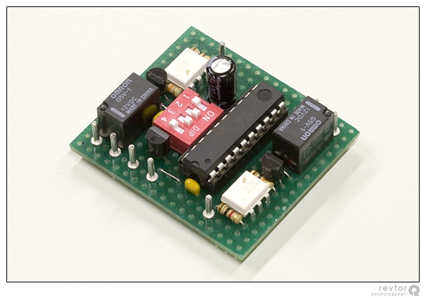
Small update. I have redone my module - this time based on a microcontroller like the jalt.de module. Not that anything was wrong with the first version, but the jalt.de module offers an extra feature and I was pointed at yet another interesting addition by someone at 8er.org. Due to the new features it's impossible to build the module on a small circuit board using classic timer ICs like the first version. Therefore I opted for a microcontroller which also means the board can be smaller. I finished the program code already nearly a month ago, but I hadn't found any time yet to build the actual board. Until now:
The two small white ICs are 4N25 opto couplers. Because of the new full flash functionality the unit has to monitor the output from the E31 flasher relay. Although not strictly necessary, I found it safer to isolate this from the microcontroller. Hence the opto couplers. The small DIP switch block makes it possible to change various settings without reprogramming the unit.
A short explanation of the features:
Comfort blinker: The comfort blinker or one-touch turn signal will cause the turn signals to blink a preset amount of times after shortly tapping the turn signal lever.
Comfort blinker cancelling: Sometimes you still want to be able to do short blinks. By holding the turn signal lever for just a moment longer the comfort blinker is cancelled. Not all cars with a comfort blinker offer this feature, but since it can be enabled/disabled in my version, why not?
Full flash: Normally when you release the turn signal lever or when the comfort blinker timer stops, the blinking will stop immediatly. It's possible the last blink is more like a short flash than a full blink. The full flash functionality makes sure each started blink is completed. In other words, each blink is equally long no matter when you released the lever. The only exception is of course when you switch directions. You don't want the car to blink in both directions for a short moment (I haven't tested whether or not the E31 flasher relay can be fooled like that, but I thought it was safer to implement it in my module anyways). This is of course a purely cosmetic feature, but what the heck...
Differences in functionality between the jalt.de module and my two versions of the one-touch turn signal module:
One disadvantage of the new module is the fact that it requires twice the amount of wires to the E31's wiring harness (8 wires versus 4). Most are easily accessible in the steering column or below the dashboard, but the flasher relay's output is a bit less comfortable to reach (connector X14 in the left hand footwell).
In case anyone's interested I can draw a print & components layout view and publish the program code so you can reproduce the board. Since it's smaller than the original version and requires less traces, it's easier to build... But keep in mind that you will need a microcontroller programmer for the Atmel AVR microcontroller series! It's probably a bit stupid to buy a programmer just to be able to build this single module. In that case you better go with the first version or the jalt.de module.
Member
Hi!
Please, if possible I need schematic, layout, and software to build this module!
Thanks.
Member
I can produce the schematic and layout in a few days, but do you have an AVR programmer for the Atmel ATtiny2313? The source code is written in C, so you'll also need a compiler.
Member
Yes! I have compiler and a home built AVR programmer.
Member
....we are just trying to make room for your new Belgium beer Budweiser
Member
mumtaz: Here you go: One-touch turn signal module. I wrote a complete new article regarding the newer module. It's written with the 8 Series in mind, but there's enough information in it to get the module working in other cars. Sorry for the delay, but other work came inbetween...
Enjoy!
Last edited by revtor; 05-02-2009 at 11:24 AM.
Member
WOW man. This is incredible. I just wait a simple schematic (maybe a layout). And I (and others) got a complete novell.
Thanks man. :-)
Member
Would you be interested in making one for me ? Thank you John
Member
Please check the schematic and partlist.
In the partlist the C1 and C2 is wrong. In the schematic the C1 is electrolytic capacitor, C2 and C3 is capacitor, but in the partlist the C1 and C3 100n capacitor, and C2 is 100µ 25V electrolytic capacitor.
Member
I fail to see the problem... The schematic has C1 and C3 as 100n capacitor and C2 as 100µ electrolytic capacitor - just as the parts list?
Update: I just spotted the problem, the PCB layout has C1 and C2 switched. I will change it in the next few days... Thanks for the heads-up!
Last edited by revtor; 05-09-2009 at 05:28 PM.
Member
Oh yes. The problem is in the layout and not the schematic. Sorry My mistake. (And sorry My poor english
Member
revtor: Something wrong to my "module". I builded the module 3 times from new parts, but 3 other plate (stripborad, engraving pcb, bread board). But I have same problems. If I test the module and connect the 12V positive to "right in" or "left in", the relays switch on, and not switch off. After I switch off the module, and switch back on, the relays is switch back on without the "right in" or "left in" connected to the +12V.
If I change the ATtiny to other new one programmed ATtiny, the first time is ok, but later have same problem, so the first "in right" or "in left" connect to +12V completly kill the microcontrollers.
I killed 5 ATtinys.
Any ideas? Maybe change the "in left" and "in right" direct connect to an optocoupler or what?
UPDATE: Ohh. This is My mistake. So. Now I use optocoupler to switch. This work
Last edited by mumtaz; 06-27-2009 at 12:45 PM.
 Posting Permissions


 Reply With Quote


Bookmarks