
 Member
So my 1996 328is is a used machine, has almost 150k miles on it, and has been mine for just over a year. After reading in these forums about all the cooling system troubles and pathetic plastic part problems, I decided to refurbish the entire cooling system. Plus anything else that looked likely to crap out. And do the Fan Delete Mod (FDM) to see if that works for me (but I'm ready to go back if I have overheating).
There are lots of DIY's out there, some with helpful pictures, and some pertaining to non-328 vehicles or non-M52 engines and so not very useful to me. The Bentley Service Manual is also a good resource, but sometimes it also gives a too-simple explanation or even ignores my 328/M52 variety of vehicle.
You gotta work thru the problens, here's what I did:
Member
A good web source on flushing the coolant from your E36 is:
www.unofficialbmw.com/e36/engine/e36_annual_coolant_change.html
or maybe:
www.pelicanparts.com/bmw/techarticles/E36-Coolant_Flush/E36-Coolant-Flush.htm
www.bimmerdiy.com/diy/e36coolingsystem/
1. Warm up the engine with in-cabin heat full ON, then turn it off.
:
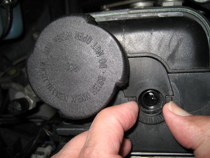
2. DO NOT OPEN THE RADIATOR EXPANSION TANK CAP.
: Remove the radiator cover over the kidney grill. This plastic flat cover
: has 4 standard Phillips screws and 2 Phillips self-tapping screws (07 11 9 907 957).
: On my 328is it also has a ram air tunnel that cools the alternator, remove it too.
: Let the car cool down so you can work with the coolant.
:
3. Look for the blue plastic drain plug (13mm) on the drivers-side bottom of the radiator.
: Also look for the engine block drain plug (19mm) underneath the exhaust collector/headers
: and pointed directly at one of the pre-cat O2 sensors.
:
4. Open the cap on the radiator expansion tank. An inch-plus away
: (towards the middle of the radiator) is the Air Bleed Valve, labeled "entluftung."
: Open the black plug about one turn with a flat-blade screwdriver.
:
5. Get your collection pan ready and under the radiator drain plug.
: Have mop-up paper towels or somesuch ready too.
: Use a flat-blade screwdriver to unscrew the plug and start draining.
: I collected a gallon or more of hot greenish coolant from the radiator,
: which is only about a third of the 3 gallons in there.
:
6. Now at this point the DIY will direct you to unscrew the engine block drain plug
: and let loose coolant from there. I could touch the drain plug with my
: open-end wrench, but I could not apply enough torque to break it free.
: Even if I could move it, the plug was going to rotate right into the wire end
: of an oxygen sensor, maybe hitting it but for sure soaking it in coolant.
: And later I'd have the problem of getting that plug back into the bung
: without cross-threading and then applying the proper torque to seal it up.
:
: Time for Plan B: The Big Flush.
:
7. I closed the radiator drain plug, started the motor (with defrost fully on)
: and fed a gallon of good Sierra Nevada tap water into the expansion tank
: until bubbles came out the bleed valve.
: Shut off the engine and collect another gallon of coolant at the radiator drain.
:
8. Repeat step 7 another 4 to 6 times, until the collected radiator water
: is thinly green indicating the coolant is well diluted.
:
9. At refill 6 I added 22 fl oz of Prestone Radiator Flush (sodium citrate)
: and ran the engine to full operating temperature, per the instructions.
: Drain again at the radiator drain, now the radiator water is soapy and not much green.
:
10 Repeat the one gallon flushes as many times as necessary so you are satisfied
: the soapy radiator flush is itself flushed from the cooling system.
: Since the green coolant has disappeared, I just dumped the collected water in the sink.
:
11 Park your bimmer on car ramps for the next days work.
: Undo as many radiator hoses as you like
: and drain as much water out of the engine as you can.
This may sound like a lot of water filling and collecting, but in the coming days as you detach the water pump and various heater hoses, additional water will dump out. It's just tap water, I catch it if I can or let it fall where it wants if I can't.
Member
A good web source on removing the radiator is in the Tech Articles at pelicanparts.com
For removing the fan and its clutch, I used:
www.understeer.com/fanclutchmod.shtml
Here's what I did:
1. I was ready to try the crescent wrench and big screwdriver technique to loosen
: the fan and clutch from the pulley, but my BMW Parts Man lent me the thin tools
: to do the job. One mild tug and the 32mm nut was free. Couldn't be easier.
: Remember: the threads are reverse rotation, so turn it CLOCKWISE to loosen.
: And it's not difficult to maneuver the plastic fan thru the plastic fan frame.
:
2. To make the next step easier, I removed the Air Filter Box. Just two 10mm nuts
: on the bracket holding the cruise controller, plus clips at the MAF sensor.
:
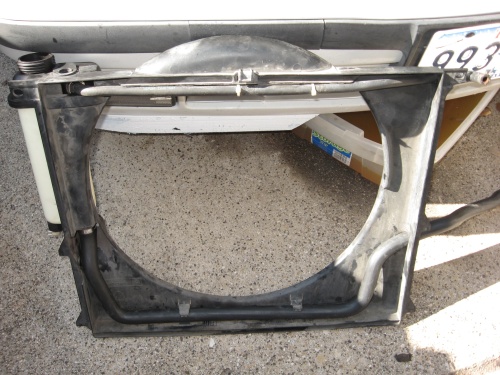
3. Now remove the fan frame with the integrated expansion tank.
: First you will have to disconnect the overflow hose (17 11 1 723 521)
: and the reservoir overflow hose (11 53 1 740 649). This hose winds around
: to the left side of the engine behind the alternator and needs to be disconnected.
: (more coolant fluid will pour out here, good thing it's just water)
:
: The fan frame is held to the radiator with two small plastic expanding rivets (17 11 1 712 963).
: Pop these out to detach the frame from the radiator.
Note: because my goal is to replace all the cooling system plastic/rubber parts, including all the coolant and heater hoses, I'm throwing them away as I go. I have all the new parts on hand so I can verify I have the right shape and size.
And since I seem to break at least one plastic fastener on every major part, I replace them all with new (unless they just hold plastic moldings or bodywork in place). Same for all the hose clamps. And metal fasteners get replaced if they're at all worn or stripped. It's cheaper now than later fighting with a doubly stripped screw. IMHO
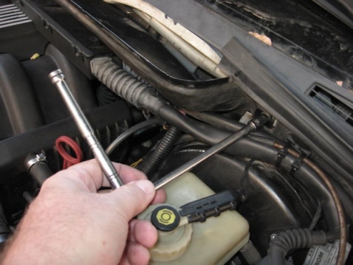
4. Disconnect the connector at the coolant level sensor.
: Remove the fan frame / tank from the car.
:
5. With some fiddling with the tabs on the entluftung, I pried the entluftung up and off
: and removed the expansion tank (17 11 1 723 520) from the fan frame.
: If you have new hoses, tank, and level sensor (before 3/96: 61 31 1 384 739),
: you can reassemble the fan frame and set it aside.
:
6. With the frame out of the way, disconnect the two hoses on the radiator. (more water spills)
: Then disconnect the electrical connector for the radiator temperature switch.
:
7. The radiator is held onto the chassis of the car with plastic clips called upper mounts (17 11 1 723 341).
: These are not difficult to remove, but I was unsure so I bought a pair. But the clips
: released easily and so I didn't use the new ones.
: Inserting a flat-blade screwdriver into the T-shaped hole in the center of the clip,
: move the screwdriver fore/aft (moving with the arrow molded on top of the clip, then against the arrow).
: With each fore/aft motion, the catch mechanism should release one tooth until the clip is free. Easy.
: It's like a tie-wrap: the springy catch grabs or releases one tooth at a time.
:
: With the clips removed, the radiator (17 11 1 469 179) is no longer attached to the car
: and can be easily lifted up and out of the engine compartment.
: (more water pours out as you carry the old unit away)
:
: Be sure to remove from the old radiator the two rubber bumpers on the right and left,
: and the two rubber inserts where the upper mounts grab the radiator. You'll need 'em for your new radiator.
Note the animal life in the radiator, snuffed by your car.
8. Remove the three 10mm bolts on the thermostat housing, then remove the final 13mm bolt.
: That bolt also attaches an engine lift hook, loosen the other bolt holding that lift hook
: and the thermostat housing will be free to come off. You may need to pry a bit to get it off.
: Throw away the old orange gasket seal.
:
: My replacement housing is aluminum (11 53 1 722 531) and comes with a new gasket.
: If your original housing is good to go, I still recommend replacing the gasket (or any other
: O-ring you touch) with a new one (11 53 1 740 437). It's cheap assurance of reliability.
Note: Be sure every gasket groove or O-ring mating surface is CLEAN.
Your new seal is unreliable and leaky if it's pressed against a dirty, gritty, or badly scratched surface.
9. Use a screwdriver to remove the old thermostat from the block.
: Clean any dirt or corrosion from the exposed gasket mating surface on the block.
:
10 Loosen the coolant pump pulley 10mm bolts. With the belts still on, the pulley won't rotate.
:
11 Pop off the covers on the (self-adjusting) belt tensioners on the A/C belt
: and the alternator/pump serpentine belt with a small flat blade screwdriver.
:
: With the poly-ribbed belts, replacement is a snap and is simply described at: www.pelicanparts.com
: The tensioners that hold the belts tight can be easily released using a socket or Allen hex tool.
: On my 328is, the A/C belt tensioner is loosened in a clockwise direction with an 8mm Allen hex tool.
: And the serpentine belt is loosened in a clockwise direction with a 16mm socket
: (a 5/8" socket will do too).
:
12 Remove the coolant pump pulley bolts, remove the pulley, remove the coolant pump nuts, all 10mm.
:
13 Thread two M6 bolts into the threaded lugs on the sides of the old pump.
: Tighten the bolts (10mm), they will push the old pump out of the block. Pitch the old pump.
: (more water pours out of the engine block, I'm glad it's pollution-free)
: Note: if the impeller is shattered, good luck getting all the old pieces out of the block.
Indeed my pump was original with the plastic impeller. While it looked OK, on closer inspection I saw a radial crack in the top disk. And the plastic had a light/dark mottled appearance, kinda like the ripples of light on the bottom of a shallow creek or pool. I grabbed an edge with two fingers, it seemed flexible and (oops) a chunk broke off! Just like that!
I'm glad that pump is outta my car, even if it did last 150k miles.
The replacement pump will have a steel impeller (11 51 1 433 828).
And both belts have dry ribbing with LOTS of cracks, they're getting replaced also (11 28 1 437 873 and 11 28 1 437 929).
Member
Today I need to decide: if I'm going to replace all the heater hoses then I have to remove the intake manifold. Do I need/want to? Some forum commenters claim they can reach and replace all the hoses without removing the manifold. Maybe they can, maybe they've done this before. I can't, there's too much crap under there, I can't see stuff, I don't know what it all does.
Some have suggested removing the outside air intake plenum (the gray grill) and the heavy plastic plenum that the cross-bay cable box attaches to. This allows easier access to the heater hoses attached to the firewall feed-thrus. It will also make removing the intake manifold easier. So that's what I'll do.
Maybe there's a DIY that addresses removing the cabin heater fan that would get me started on removing the air plenums, but I can't locate one so I'll just use Bentley. Section 611 on wiper removal explains all I need:
- remove the windshield wipers
- remove 6 plastic fasteners (twist them off like screws)
- tie the gray grill up and out of the way, doesn't actually have to be removed
- remove two Phillips sheet metal screws and unclip the cross-bay cable box from the center plenum
- remove three 7mm sheet metal screws on the center plenum and pull it out
- move the cross-bay cable box out of the way as best you can
I had a hell of a time breaking the wiper arms loose from the driving axles. I tried Liquid Wrench, a heat gun, levers, rubber mallet,... It took hours but next time will be easier.
A good web source on removing your fuel injectors is: http://e36-tech.com/DIY/5speedswap.htm
or again, pelicanparts.com in the Tech Articles directory,
or also: http://bimmer.roadfly.com/bmw/forums...1908968-1.html
For removing the intake manifold there's a DIY on pelicanparts.com but it doesn't directly address my 1996 328is. So I will use Bentley and my own notes to get me thru this.
1. Get the outside air intake grille and plenum out of the way as mentioned above.
: The air filter box is already off, now detach the MAF Sensor and rubber elbow
: from the Throttle Body (TB), and detach the vacuum hose from intake manifold
: to the brake booster tank (pull it off of the intake manifold nipple).
:
2. Loosen the four 10mm bolts for the throttle body and simply let it hang.
: Be careful of the throttle body cables when you detach the TB, as you dont want to twist or damage them.
: You'll be moving the TB around as work proceeds, be gentle.
: Also, if it's dirty give it a wipe with alcohol; I'm not sure if there's Teflon in there
: so I won't use any petroleum distillate (Techron) product. Alcohol works fine.
: And of course you have to detach the connector for the Throttle Position Sensor (TPS).
:
: I will also put on a new TB profile gasket (11 61 1 716 174) when I finally reassemble everything.
: And I'll be cleaning the gasket groove and the mating surface on the manifold too. That's standard.
:
3. Now onto removing the Fuel Rail and Injectors.
: First remove the electrical rail, the long black box with the connectors.
: I found that with a dental pick (ask your dentist for one) I could easily pick the right
: and left ends of the wire locking bail on a connector and gently move each end back
: and leave them pressing against the side of the connector body.
: The connector on injector 6 is the hardest, but all can be done,
: none of the wire locks went flying, and they all stayed in place while work continued.
: Demate the connector at the front of the electrical rail, move the rail aside.
:
4. De-pressurize the fuel rail by pushing in on the Schraeder valve on the front (remove the cap first).
Note: On the fuel rail is what looks like a tire valve. As stated in the Bentley manual this is used to clear the fuel rail of fuel (attach a high pressure inflator and clear fuel before removing injectors. This will push the fuel back into the gas tank). It makes for less mess when removing the injectors but you'll still get gas spillage.
: Cleanliness continues to count: remove any loose dirt around the fuel injectors before you remove them.
: You don't want random gravel falling on the valves and into the combustion chamber.
:
: Remove the two 10mm bolts that hold the fuel rail on the manifold
: and gently but firmly pull up on the rail until the injectors release (pop out from the manifold).
: The only resistance you'll feel will be the O-rings at the base of each injector.
: Some may be stiffer than others, so take your time to work them loose.
: Have rags handy for excess gas spillage.
: Be careful of the injector tips and don't bend the fuel rail: they're all expensive parts!
:
5. A brass clip holds each injector to the fuel port on the rail. Use needle-nose pliers
: to pull each one off. Now you can pull the injector from the fuel rail port.
: Again, the only resistance will be O-rings, so work each one out gently.
Note: You can decide for yourself if you want your injectors professionally cleaned (about 15$ each) or try it yourself. I used Techron Injector Cleaner and an old toothbrush to brush away the carbon deposits. AFTER I get everything back together and running I may get mine cleaned, in case I added more contamination than I got rid of. 'Cuz now I know how to get them off.
[NOTE: everything runs fine, I'm not getting the injectors professionally cleaned]
6. Now that the fuel rail is out of the way, remove the seven 11mm nuts from the intake manifold and put them away.
:
: I found the safest place to leave the fuel rail after extracting the injectors
: was back on the manifold, just finger-tight with the 10mm bolts.
:
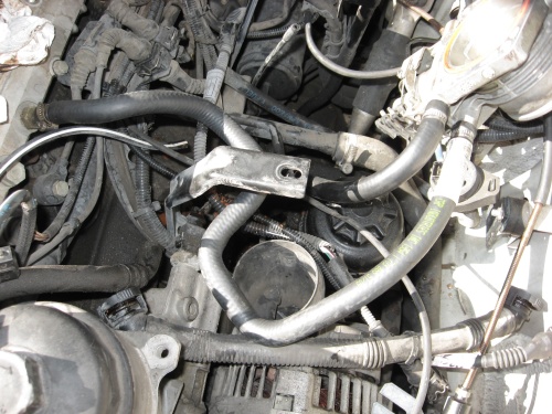
7. Now we move to the other side of the manifold, where there's more stuff in a really cramped space.
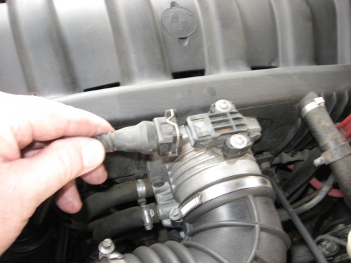
: Begin by removing the Idle Speed Control Valve (ICV). There's DIY's on this somewhere.
: Detach the fresh air input hose (from the MAF elbow) underneath, detach the connector at the back,
: and remove the three 10mm bolts on the little plate attached to the bracket underneath the manifold.
: One of those fasteners holds the oil dipstick tube in place, the other 2 are for the ICV.
: The ICV pulls out of a port on the bottom of the manifold, pop it out, remove it, put it away.
Note: The ICV is probably dirty. If you snap the ICV with your wrist in a rolling motion, you should hear the metal valve inside the ICV rattle back-and-forth with a metallic click. Mine did. Nevertheless I decided to put a small amount of Techron inside the ICV and wipe out the carbon deposits. I got carbon, but almost immediately the internal valve moved to fully open and stuck there! I thought I had crapped out some internal plastic part and ruined my ICV!
I kept wiping it out, using alcohol now, and snapping my wrist trying to free it up. Finally I got my power supply and applied 10-12VDC to pin 2 and ground to pins 1 or 3. A few times of power application and wrist snapping and the valve freed itself. I guess it was some loose grit jamming the valve, we'll see if it works.
: Finally the gas lines to the fuel rail are attached to the bottom of the manifold with a bracket
: and a single 10mm bolt. Rather than detach that bracket, I decided it was easier to go under the car
: and undo the 2 hose clamps at that end of the gas lines. Later when putting the manifold back,
: it wasn't difficult to guide the lines back down and reclamp them (new clamps of course).
:
8. Remove the two 10mm bolts from the brackets to the bottom of the manifold, one at the near front
: and the other at the far rear of the unit. DO NOT remove any fasteners that hold the center bracket
: or other parts to the underside of the manifold. It's not necessary and we got enough loose parts now.
:
: Detach the connector underneath for the Intake Air Temperature (IAT) sensor.
: Detach the 3 vacuum lines (2 small, one a bit larger) from underneath the manifold.
: They don't have to all detach at the nipples on the manifold, find the easiest end to pull them off.
: And note where they re-connect, the vacuum system has to be complete when you put everything back together.
: Detach the vent line from the cylinder head to the whachamacallit underneath the manifold, it's a quick-release type.
:
9. The intake manifold should now be free, if not track down the hitch and detach it too.
: With the plenum removed, it should not be too hard to get the lightweight manifold out.
:
: Take a look inside your engine, note the carbon build-up, and immediately cover the ports.
: We don't want foreign matter or loose screws getting in there.
: Call it a day, it was for me.
There was a lot of carbon inside the manifold too. I decided to swab that out with Techron. But first remove the fuel rail, it doesn't need the extra handling nor exposure to carbon grit. Clean the fuel injector ports also.
I made a big Q-tip by slipping a string thru the center of a small pipe and trying a lump of rag (wet with Techron) to the end. This ensured I had a grip on the rag and it would not slip off of some wood stick and get jammed inside the manifold. I could tighten or loosen the string as needed as I swabbed in-n-out of the airways. As the rag got dirty, I changed it. And at the end, I sloshed some alcohol thru the airways; alcohol is cheaper than Techron and it evaporates quicker.
Last edited by berkeleyEE; 02-25-2009 at 12:29 AM. Reason: update
Member
I've basically got everything apart, now it's time to replace the heater hoses and start putting my machine back together.
1. I replaced these heater hoses:
: 64 21 1 394 291
: 64 21 1 394 292
: 64 21 1 394 293
: 11 53 1 703 844
:
: and these throttle body cooling hoses:
: 13 54 1 703 865
: 13 54 1 703 945
:
: Double-check your torqueing of the new hose clamps before covering them up.
:
2. I put new profile gaskets (11 51 1 740 069) on the manifold ports,
: lightly oiled for a good seal and to keep them in place while I man-handle the manifold.
: And I gave the mating surface on the head a final wipedown for good measure.
:
: The manifold went into position easier than it came out, guiding the protrusions and gas lines
: as needed. I hooked up the vacuum lines (I think I got them all).
: I placed the ICV back where it belongs, not too difficult either.
: Reattach the oil dipstick tube, reconnect the electrical connectors, reattach the air input
: to the ICV, fasten the brackets to the bottom of the manifold.
:
: Place the 11mm nuts on the manifold head studs and torque'em down.
:
3. If you've got everything attached, move on to the throttle body and MAF sensor.
: As always, the TB gets a new gasket (11 61 1 716 174) at the manifold too.
: Reattach the vacuum line to the brake booster.
:
4. Starting with injector port 6, place the injector into the fuel rail port and snap it in.
: Add the brass lock. Be sure each is in correct position.
: Repeat for each injector in turn.
: Finally align all 6 injectors with the manifold ports and snap them into place.
: Inspect for proper seating and alignment of the connectors for the electrical rail.
: Don't forget the little bracket in front that holds the electrical valve for the Secondary Air
: check valve, include it when you fasten the fuel rail with its 10mm bolts.
:
5. Put the intake air plenum back, reattach the cross-bay cable box, reattach the gray plenum grill.
: If you removed any tie-wraps, replace them.
: Reattach the wipers.
:
: Review your work, expecially the water hoses and the vacuum tubing.
:
6. Now to the front end of the motor.
: Lightly lubricate the O-ring for the new coolant pump (11 51 1 433 828) with a bit of oil
: (or coolant or lithium grease).
: Install the new pump in the block (get the orientation right for the M6 extraction bolts),
: install and tighten the nuts.
: Install the pump pulley and start the pulley bolts.
:
7. Get your belts (I'm installing new ones).
: Relax the belt tensioner (clockwise) and install the serpentine belt.
: Tighten the pulley bolts and replace the dust cover over belt tensioner pulley.
: Repeat the belt installation for the A/C belt.
:
8. Install the new 80°C thermostat (11 53 1 466 174, 'cuz I'm doing the Fan Delete Mod)
: in the block with its new O-ring (also v lightly oiled). Be sure to have the arrow pointing up.
:
9. Install the new aluminum thermostat housing (11 53 1 722 531). I v. lightly oiled that gasket too.
: Start the three smaller bolts, then start the larger 13mm bolt with the lift hook back in place.
: When all are threaded well, torque 'em: the three 10mm _and_ the two 13mm.
:
10 Prepare the new radiator (17 11 1 469 179). Place the rubber bumpers on the sides
: and the rubber inserts on the top slots. If you don't have them, the radiator won't be secure!
:
: Install the 22mm radiator dual-temperature switch (80°/88°C: 61 31 8 376 440). Don't over-tighten.
: This switch is not for my later E36: it has a key slot on the right but the mating connector
: has the key on the left. Take a look, you'll see. So take your Swiss Army knife and trim away
: the key on the connector. Then it will fit switch units for any year E36.
:
11 When you install your new radiator, make sure that it sits firmly on the mounts attached to the chassis.
: It is possible to install it slightly cocked if you don't pay attention to these mounts.
: If you damaged your plastic clips (17 11 1 723 341) removing the radiator,
: be sure to replace them with new ones. Be sure the clips mate with the rubber inserts.
:
12 Install the radiator hoses (11 53 1 708 499 and 11 53 1 726 344,
: or equivalent if you prefer something different; I have silicone hoses from Bimmerworld).
Note: the blue Bimmerworld hoses seem a bit longer than the originals. So they touch stuff.
: Use high quality hose clamps for best reliability, not the dollar hose clamps from the hardware store.
: I left the top hose loose at the radiator end so I could put the first gallon of coolant in there first.
:
13 Check the expansion tank to be sure it's ready for installation. You might leave the level sensor loose
: as I had to loosen the tank and move the level snsor connector to a new position so it would
: mate correctly with its plug. But then be sure to tighten it before adding water.
:
: Install the tank and fan frame, pay attention to the clips and slots it fits into.
: Use new expanding rivets (17 11 1 712 963) to attach the frame to the radiator.
: You'll probably have to pull up the entluftung and free the expansion tank to get that rivet in.
:
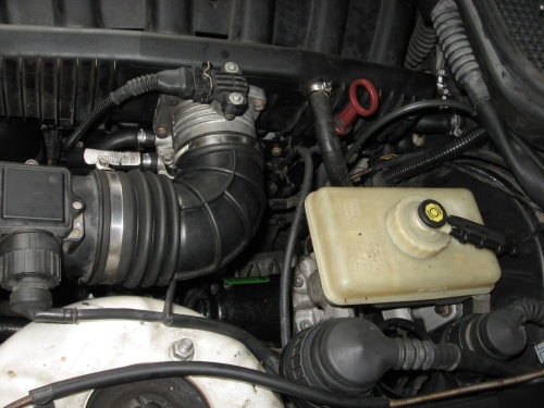
: Be sure to connect the expansion tank small hose to the radiator top
: and connect the tank large hose to the coolant pipe back on the left side of the engine.
:
14 Review your work again, it's time to add 50/50 water and BMW blue coolant.
: I added one gallon straight away at the radiator top hose going to the engine block.
: The second gallon I added slowly and not all of it went in. So clamp the hose to the radiator
: and move on to adding coolant at the expansion tank. As much as it will accept.
:
15 Put the air filter back in and attach it to the MAF sensor and bolt it to the cruise control module.
: Put the air pipe to the alternator in. Finally put the radiator cover back on.
:
16 Bleed the cooling system.
: The best DIY for this is described in: www.understeer.com/fanclutchmod.shtml
: as part of their Fan Clutch Removal Mod. But experience is the best teacher.
:
17 When you first fire up the engine, be alert for coolant leaks (obviously),
: for vacuum leaks (I had none luckily), and for gas leaks at the fuel injectors
: and under the car where the gas lines were detached (also none for me).
So it all looks successful, pretty good for a newbie with access to a lot of resources. But I'll be watching the temp gauge and looking under the hood for next few weeks, just to be sure.
Member
OK, so these "days" are days in the biblical sense: periods of time not particularly accurate to anything. I did the 328is refurbishment in July and then drove it normally around town and on the freeway, always alert to the temperature gauge and with a gallon of water and a few tools in the trunk.
The road trip was up I-5 in August, thru the Sacramento Valley, over the Siskiyou Summit, on to Oregon, Washington and back.
All is good. I know I improved the reliability of my vehicle. I don't know if the Fan Delete hurt anything, but for sure there's no harm.
And the cost? At first it appeared to be 500 to 600 dollars for all the cooling system components, mostly at an independent parts retailer but some from the dealer. But when I needed coolant, fan belts, manifold gaskets, lotsa small plastic fasteners, etc on the same day then I went to the dealer. So my final cost was 900 dollars.
And the experience? Priceless.
Member
wow.. what a long detailed write up. good read.
Member
this is going to come in handy as I planned to do all of this in the coming months as well. one thing kinda scares me though, your final cost. I was aiming to be under 500 with pullies/FDM/pump/Tstat and housing...
Member
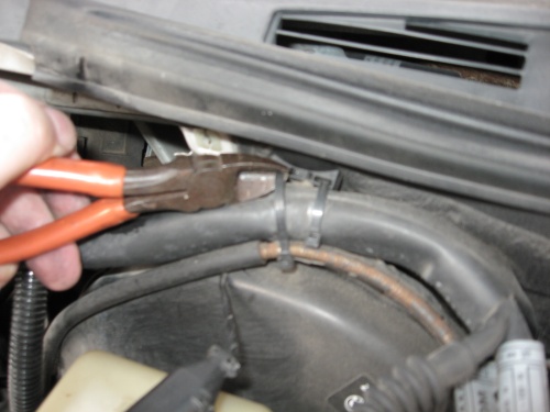
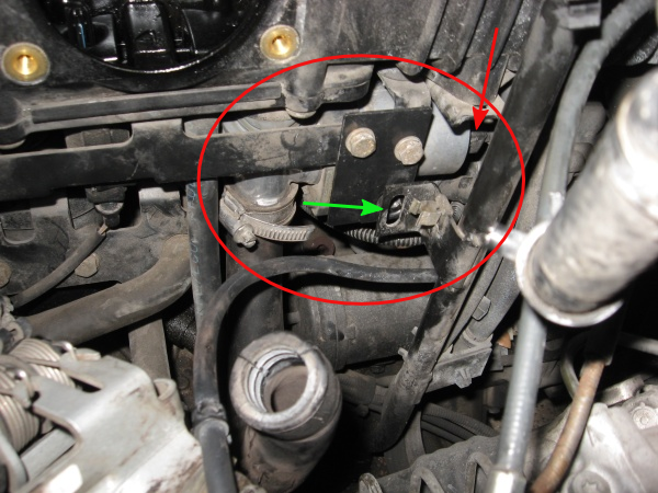
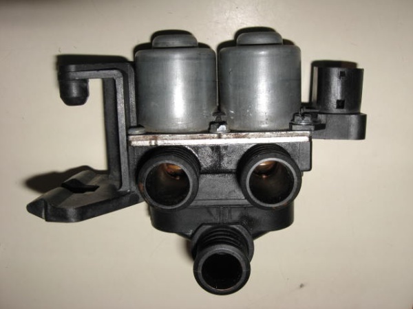
With some fiddling with the tabs on the entluftung, I pried the entluftung up and off
Can you give more details on how to remove the expansion tank? I had a hell of time yesterday trying without any success to push the rivet pin in with the tank in the wayway.
Member
If you disconnect everything from the Tank, it comes right out.
Here's the trick to pinching the ears on the entluftung to get it up and off:
Entluftung.jpg
Member
Nice writeup
92 325i- afe intake, bavauto coils, m3 h&r race springs, m3 koni yellows, m3 solid rubber bushings, sparco strut bar, TMS sway bars, bavauto chip, shorty headers, AA track pipe, borla exhaust, evosport pullies, FDK, stewart waterpump, silicone intake hose, silicone rad hoses, alum rad, reinforced subframe, brembo BBK, 3.23 LSD, uuc weighted shift knob, AA short shifter, m3 bumpers, DS1's, TURBO S50 BUILD IN THE WORKS
06 GSXR-600- jardine gp1 pipe, PC3, RK quick accel kit, k&n filter
04.5 duramax CCSB- K&N filter, AFE turbo inlet pipe, 4 inch turbo back straight pipe, PPE xcelerator 120hp tune, 6 inch tip
Member
That helped. Thanks.Originally Posted by berkeleyEE

Member
Great Write up berkeleyEE ... worthy of an engineer!
I had read this when doing research last spring for my upcoming heater hose replacement. I knew my Heater Control Valve (HCV) had frozen up and with the well documented cooling system issues and potential high cost of any failure had decided to replace the rest of my cooling hoses. I had done the basic cooling system rebuild (radiator, upper/lower radiator hoses, water pump, T-stat, t-stat cover) a little over a year ago. So with the heater hoses, throttle body hoses, expansion tank and hoses I also figured the only way was remove the intake manifold. As a plus I also wanted to replace all rubber vacuum hoses under there and I had some idle issues at cold start so good time to clean out the Idle Control Valve (ICV). But by the time I got around to doing the job at Thanksgiving I had lost track of this thread, so unfortunately I had to reinvent the wheel. It does seem I did most things the same way you did. As you mentioned, there was very little in a single spot on doing this task which surprised me. I had looked through the DIY forum also with no luck. So I hope you don't mind if I ask a moderator to move this thread to the DIY forum. It covers all aspects of rebuilding the cooling system so people that are searching for more specific individual tasks would have a hard time finding it with general search terms.
As my contribution I will quote your instructions on just the intake manifold removal and cooling line replacement and note any observations I had in red. I will also add some pics I took of the process to help illustrate things. I wish I had taken more pics, but I really was taking them more to help me remember where things were than thinking of a diy write up so several areas are missing pics that would be helpful.
Continuing to note my observations in red and add some pics I took of the process to help illustrate things. I wish I had taken more pics, but I really was taking them more to help me remember where things were than thinking of a diy write up so several areas are missing pics that would be helpful.
After finishing this up I have a LOT more piece of mind. Plus the car idles better from r&r the ICV and fixing small vacuum leaks and I have HEAT!Again the best thing is knowing every single component in my cooling system has been rebuilt/ replaced. ... well other than the heater core, keeping my fingers crossed on that one!
SUMMARY:
Total time to remove/install intake manifold, all the hoses underneath, remove/install radiator shroud, expansion tank and hoses about 9 hours less some lunch/break time. You could probably save at least an hour on that with the tips posted above. With the shroud already off the radiator, upper/lower hoses, water pump and t-stat would probably add on a little over another hour. So if you needed you could knock everything out in a long day.
My Parts List:
11 72 7 545 323 Vacuum Hose $ 5.00 a meter
11 61 1 716 174 Throttle Housing Gasket $ 4.70
11 61 1 740 069 Intake Manifold Gasket $ 6.00 each (two needed)
13 54 1 703 865 Block to Throttle Body Water Hose $ 11.00
13 54 1 703 945 Throttle Body to Coolant Pipe Water Hose $ 5.06
11 53 1 740 649 Expansion Tank to Heater Coolant Pipe Hose $ 13.52
17 11 1 723 521 Radiator to expansion tank overflow hose aprox $10
11 53 1 703 844 Heater Core to Coolant Return Water Hose $ 7.65
64 21 1 394 291 HCV to Firewall Heater Hose $ 6.86
64 21 1 394 292 HCV to Firewall Heater Hose $ 9.21
64 21 1 394 293 Block to HCV Heater Hose $ 6.06
17-11-1-723-520 Expansion Tank $40
61-31-1-384-739 Coolant Level Sensor 18.00
Total just under $160 from Cmuzyy at BimmerParts.com (forum sponsor), see group buy forum. The radiator, upper/lower lines, water pump, t-stat and housing I got in a group buy for like $300. So complete system rebuild parts if you shop can be had for $460 range. Various clamps, connectors, wire ties budget $20 and a gallon of BMW coolant ($20). So total budget a little over $500 with shipping.
If you are not doing the Fan Delete Mod, take a hard look at the clutch fan, they fail about this time too. Any visible leakage, usually seen as dark, wet looking crud clumped to the fins, and it is done. Mine went last spring ... you can find the OEM Behr for around $100, aftermarket around $60. I got a new Behr from ebay for $50.
Thanks for a great write up berkeleyEE!
edit: well I tried to do each day in a separate post like the original, but I guess the forum software didn't like that and merged them all together. Oh well one huge post!
Last edited by paniolo; 12-16-2010 at 03:39 PM. Reason: Automerged Doublepost
David M.
'96 328 Sedan
Member
Great write up. On my m52 the tranny cooler is attached to the radiator. Did you remove the tranny cooler with the radiator, or detach the tranny cooler from the radiator?
Member
Is that black canister with the hose part of the evap system? My 96 E36 M3 does not have it.
Though it does have a large canister under the spare tire in the trunk
Last edited by Bimmerman4ever; 06-10-2014 at 05:09 PM. Reason: legally blind and certified insane
Member
I'm wondering this as well, I'm doing this next week on a 328is with auto transmission. Hopefully I can get the cooler off the radiator, I don't feel like adding a trans top off to the list.
The photos and details that were added were awesome, should help me a bunch.
I'm also going to rebuild the injectors and change the fuel filter while I'm there. I bought a fuel injector rebuild kit off ebay(comes with new tips rings and filters), and a new oem radiator from ebay, and a level 2 coolant hose kit for M52 from FCP and intake gaskets.
I'm new to bmw lol this is gonna be fun......
Last edited by intj123; 08-29-2014 at 01:39 AM.
Member
Member
The 2 O rings to the heater hose pipe was included in the kit I bought from FCP (M52 comprehensive hose kit) which they horribly messed up my order with 1 missing hose and 1 febi brand hose instead of OEM hose they gave me. So watch out if you buy this off them, check that you have all parts and that they are the correct brand before starting the job, they are shipping me the missing hose very slowly....(7 days from when I called) and I had to contact them for a partial refund on the non oem hose.
This is the kit and the part for the 2 O-rings should be
2x O-Ring 11531703848 Reinz
$1.43
http://www.fcpeuro.com/products/bmw-...s52-m52hosekit
The O-Rings are not shown in the photo, but it is listed on parts included list, and I did receive them.
Now since they are making me wait so long, I decided to start checking other stuff around there while I had the intake manifold off. I have now ordered new genuine bmw fuel rail feed and return fuel lines, and a new CCV (aka PCV) with new grommet.
This seems to be the perfect time to change that CCV out as it has been reported to cause some major oil problems if it breaks.
They go from as little as $25 Chinese - $90 for oem. I bought a hamann brand CCV off ebay and a new grommet for $46 shipped for both.
I was confused with the grommet and not sure if I even need on because there was no grommet when I removed the CCV and there doesn't seem to be much space for one.
http://www.ebay.com/itm/CRANKCASE-OI...5c1420&vxp=mtr
This link shows one of the cheapest CCV kits with all the parts needed, I didn't buy this one but you can see the grommet on the very left side of the picture, I just bought it just in case, seems like it would be important if I'm supposed to have one.
Member
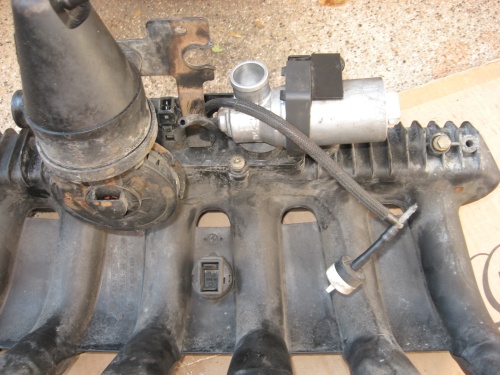
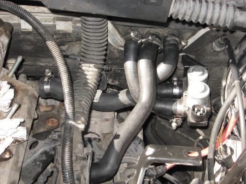
See this video to see "guts" below intake manifold:
92 325i intake manifold removal part #2
https://www.youtube.com/watch?v=FPKsexU1mqk
[ good guide for DIY ]
He is using blue silicone vacuum hose, from FPR (Fuel Pressure Regulator) to intake-manifold. See attached pic
I'm getting the blue silicon vacuum hose frome here:
https://www.ebay.com/itm/4mm-Silicon...m/232137327265
NO MORE rubber vacuum hose for me!! they eventually deteriorate/fail.
 Posting Permissions


 Reply With Quote


Bookmarks