
 Member
The strut tower problem:
After 10 minutes of hammer work, still needs more:
Notice that I'll be doing some welding and painting on the outer edge. Initially, I was considering replacing the whole inner apron, but after beating on it a bit, I think the cut and reweld would likely cause more problems than it fixed. The gap is already 1/2 of what it was prior to the hammer work. I suspect with a custom built mandrel and more body hammer work I'll be able to restore most of the original shape. Since I'll be doing some paint work there, I'll probably stitch weld the entire cap as I'm increasing the front spring rate.
yes, new mounts, new reinforcement plates are 'in the mail'. TC Klines are here ready to install.
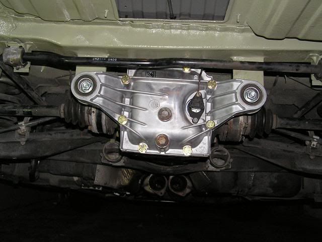
Now for the part that I overlooked when I purchased the car.
Poking around the car, I realized the subframe/suspension carrier was replaced as well as the left corner of the suspension. Alignment sheet shows the car all within spec, but the hidden damage hadn't been repaired yet. *note* 98% of this rear damage was covered by the factory seam sealer and dynomat that had been in there for years. Not until I tore back the seam sealer did I realize the extent of the damage.
Sorry I blew out the photo. Wasn't paying attention. With the jack and a 2x4 block on the end, I was able to push the metal back straight and repair from the rear of the car forward. (basically, in opposite direction of the point of failure)
My Harbor Freight transmission jack proved to be just the item I needed.
And no thread is complete without pictures of my future helper:

Last edited by brad bedell; 12-10-2012 at 09:39 AM.
Yeah, that just happened.
Ha! Last picture is hilarious. Just make sure you save a few projects for him down the line...
DIY/Project Links:_TC Kline D/A & Suspension Refresh_|_Oil/Engine Cooling Options / Install_|_
Dinan/Fikse FM-5 Build_|_Stereo Install_|_HID Retrofit_|_
Member
Thanks! He's a bit of a clown already. After 40 years without children, he's my first. It's fun to see his personality develop.Originally Posted by BMWBergy

I'm sure he'll have plenty to tinker in the in the future. I had mastered a screwdriver by the time I was 2. I'm not sure his mom is looking forward to our 'bonding' time in the garage. Especially when that boding will likely involve a, paint gun, welder, mill or lathe.
I suspect "we" will build a bicycle before we do any car work. Fortunately, we're a few years away.
More pics of the car by this weekend. I had to order a whole stack of parts. Remind me again, why I didn't buy Randy's 'kit'? I bet it would have saved me 10-12 hours plus his guidance would likely have saved me more than a couple years in learning.
Member
Notice the crack in the front left corner of the battery hole. I think dragging around that 85lb battery has as much to do with the trunk floor failing as the diff mount pulling down does. I went with a light 12 lb battery for autocross and my damage has stopped. I have the same crack at the corner of the battery hole and a few slightly pulled pop welds but it hasn't gotten any worse since I put a light battery in.
Member
*nod* it's a problem of too much flex back there. The vibration of the differential really doesn't help. I'm tempted to yank the whole floor out and build it out of a thicker metal. I'd get to buy a bead roller to reshape the pan then.
Fortunately, because it's thin its' easy to manipulate.
Member
Yes, metal working tools are always fun, if only I had the room.
Member
A little progress this afternoon. In retrospect, I probably would have been better peeling the trunk floor off the frame bit and cleaning it up. I have a bit of a mess to clean up as the metal was really dirty between the layers. Nothing 10 minutes with the grinding wheel won't fix, but I don't like having to clean up a mess when I'm using a TIG. I had to put more heat to it than I'd have liked to get the weld to be solid. I bet 8 out of 10 spot welds were bad. I still have a few more to inspect/touch up but first glance, they look and feel solid. What's interesting is the differential bracket itself was VERY solid. All the welds were in tact and didn't come off without a serious fight. Even with my spot weld cutting bit.
I've got daddy duty tomorrow but expect to get some real progress done on Friday and Saturday. All my parts will be here and I can start mocking up the bracket/support system that I've decided to fabricate.
I've also figured out how to build a mandrel tool to help shape the strut tower again. It's been a while since I fired up a lathe, I may go borrow one vs try and use the little one I have here. He's got better lathe tooling than I have.
Sorry for the cell phone pic It'll have to do.

Member
A bit more progress today. Only had a couple of hours to tinker with it. I also got the differential cover mocked up and the tabs cut. I need to trim the trigger/impulse wheel or wait for the new one. Dealer swears it'll be here by mid next week. I do wish I had slipped some sandpaper between the trunk layers. It was nasty between the layers and getting a good weld required me to more or less make a mess. I still have a little cleanup work with the dremel, but Once the seam sealer is in place, it won't be seen, so I'm not "too" worried about it.
I may prepare the car for a proper set of coilovers on the rear and reinforce the shock towers and tie them together with a rectangle channel of some sort that's tacked to the bottom of the convertible/firewall. We'll see. I want to get the rest of it buttoned up and then decide how motivated I remain.
Called it quits. Made a mess initially with my MIG. Seems 110v mig isn't enough juice (or I'm doing something wrong) I quit and just dug out the TIG. I so need to get a better process for this as laying on my back, pedal control and avoiding popping dirty metal doesn't allow me to relax and concentrate on my beads.... On well, it's going under seam sealer anyhow.

Last edited by brad bedell; 12-02-2012 at 10:06 PM. Reason: Automerged Doublepost
Member
Had about an hour tonight. I at least got the tabs welded up:
Top side is next. Will weld in the frame rail reinforcement next chance I get.
Member
coming along nice!
Member
Made a little progress today.
I found a pretty close etching primer. It's a little more green than OEM, but with a coat of dirt on it, it'll be VERY difficult to tell. you can see the 'blend' line below.
You can see the 'blend' here, in more accurate color contrast. This is more or less how it is seen in person:
What caused this diff tab failure?
The damage on my car was likely a combination of a curb on the left rear that replaced the sub-frame and left control arm in 2007. The struts both looked to be OEM of 75k miles. Both were worn equally. The bulk of the damage was likely that curb as the front two bolts of the sub-frame left their tattle-tale mark in the structure above it and the heat shied. After that, just time weakened it more.
Last edited by brad bedell; 07-29-2013 at 08:46 AM.
Member
Close copy, I hope that nobody mistakes it for the one I produce.
Last edited by Randy Forbes; 12-10-2012 at 02:19 AM.
Ralph
No danger Randy--not that good a copy--but it is a good demonstration as to the value of your kit. How much better would this job have come out if the the OP had bought your kit and followed your procedures and recommended materials (and had the benefit of being able to contact you throughout the instal). It's a shame really, because the real cost of this job is the labor, not the kit, and here he has done all the labor plus, to end up with something less than he would have if he had installed your kit, all for the savings of just a few hundred dollars--and he clearly has the skills and facility to install your kit. There is an amount of cringing associated with following this thread.
Member
Thanks Randy. I know that's as close as I'll get on a compliment on this subject. I don't think people will be confused, even without a side-to-side comparison. I will not advertise the car as your kit,now or when I sell the car in a few years. I have never implied that it was your kit. If you read, post #3 is me cursing at myself for not purchasing your kit. Not to mention, I'm sure MrBlingley will make sure his time is well-spent making it known to all future owners.
I would have gone with your kit, but have other ideas, (unfinished at this stage) that necessitated the metal shapes to be a bit different. At the end of the project, I'd have thrown away several of your pieces.
My opportunity cost of not purchasing your kit was about $1,000 worth of my time. I didn't have to purchase any specialty tools. (although, I wish I had bought a different size spot cutting tool) I have the digital degree level and 8020 extrusion for the parallel bars laying around. My calculations show that my 'savings' actually cost me $487.43 more than simply purchasing your kit.
Anyhow, I'll pick up bearings from you on the next phase with this car. I still have a few days left on finish out work with this one and then move to the front of the car.
I will add that I am currently regretting not just purchasing another twin turbo as I'm really not enjoying the sheet-metal deficiencies inherent with this car. Alas, I have agreed to the wife to only purchase disposable cars until the house note is paid in full.
*edit* Sprayed the undercoating; I couldn't find white or light gray.

Last edited by brad bedell; 12-10-2012 at 07:09 PM.
Member
I think you did a great job although I could swear I have already seen a pretty similar design elsewhere...
Still I would change some details about this kind of repair.
Best regards,
Phil
Member
Thanks Phil! I'm curious, what would you change? I didn't like doing it this way myself. If I knew my end plan would have looked like this, I would have ordered Randy's kit. But it was a work in progress that went through several revisions. The whole concept of triangulating (now a trapezoid?) the suspension through the differential really bugs me. They should be on different sets of bushings. I mocked the below up with cardboard and even managed to cut one piece out of ground 3/16" 4130 The goal was to box it and use extra differential bushings to mount it to the body (after I boxed the frame that's cut open).
Once I mocked it up, ordered the parts and rounded up a plasma cutter to finish the project, I decided to test fit the one piece that I had cut. Without moving/rebuilding the factory "I" beam frame rail and taking away some trunk, there wasn't a decent way to build the bracket with any sort of strength. I didn't even bother thinking through on how I was going to tie the the sub-frame to the new bracket together after I realized it wouldn't work.
After I trashed this idea, I bought a second OEM ear and test fit it to attempt to run two dual ear connections. This was a solid idea, but the M3 Diff cover and Z3 diff cover mounting centers was around 3/4" difference. (I'd have to check my welding table notes to be exact) With the M3 cover holes being lower. I suppose I could have slotted the holes, or bought 4 diff mounts and spliced them together. But at the end of the day, a pair of 3/16" brackets tied would out last the car. I'll loose the diff cover before the tabs bend.
I do wish I could have gotten my bead roller to bend the edges of the tabs for the diff mount. It would have made a nice finishing touch. I could have done 1/8" mild steel pretty easily but the 3/16 4130 was just too much for it.
I still have rear strut towers to reinforce, but that will be another project. My time is better spent on finishing this up and moving to the front of the car. I have quite a bit of work there and I can't cover it up with under-body coating.
Last edited by brad bedell; 12-10-2012 at 09:20 PM.
Ralph
Hey, please don't think I'm being smarmy here--I gave you credit for having the skills and facility; it just seems like a lot of work reinventing the wheel. Plus I feel like Randy Forbes has done a lot of work over many years developing and refining this particular fix for our cars, and that we should reward him for doing so not by copying his work, but by purchasing it from him. He did a really nice job on my car for what I consider to be a very reasonable price, and I happily and unabashedly promote the value of his workmanship and products, especially as he won't do it himself. You have done a lot of work on this and it shows, and I follow the thread with interest--I look forward to the finished product--I just call em' as a I see em'.
Member
Thanks for the reply and clarification.
Last edited by brad bedell; 01-07-2013 at 11:36 PM.
Coupeless Racer
Why does that bug you so much? That itself should not be an issue. Having a drivetrain item be a "stressed member" of the suspension is a tried-and-true concept, including on lots of real race cars. For packaging purposes it's often even necessary. Using the entire engine/transmission as a stressed member is very common on motorcycles for this reason.
I like the unicorns.
'99 Z3 Coupe - Jet Black/Black (1-of-114)
'99 M Coupe - Estoril Blue/Black (1-of-82)
'03 540iT - Sterling Gray/Black (1-of-24)
'16 Z4 sDrive35i - Estoril Blue/Walnut (1-of-8)
Member
I lack the formal education to properly answer your question. However, I'm sure one of our ME's could jump in and write several pages on it.
I do acknowledge that you are correct in the fact that this is a tried and true implementation. Especially so if you consider that motorcycles very rarely have over 120hp and don't withstand 1.5 tons of force in a corner. Considerably more if you dare hit a pothole. Not to mention, very few of them actually see the duty cycle of an car. (lets leave race tires, larger tires and after-market components out of this equation)
Race cars are not a good comparison as the acceptable mean time to failure expectations is considerably different in a race car than a road car. Ones that integrate drive-train and suspension are also ultra light weight.
I suspect the real answer lies in the fact that we see very few Z3's fail and a high percent of Z3M's fail. On average, M's are driven harder. Have bigger tires, generate higher forces on all planes. Had BMW reinforced the chassis for the power the M version produces, I would wager that we would be in a different thread.
With all that said, this type of repair will out-last the car and likely it's driver. Or on other-words, it moves the 'good enough' factor for me to move on and look at strengthening other deficiencies in the car.
BMWCCA #381563
Looks like the car is coming along; nice fab skills by the way.
Randy's kit really is a time-saver. I installed his kit on my car, back in 2005 and have not thought about the "sub-frame" issue since!
Member
It is a fact that the Ms fail here and that the construction sucks. I like Randys kit and will install it in my car. But there should be other ideas around. Do you have to use the diff for this. Couldn't you (not you personally... generally) lengthen the subframe and attach that by the means of bushings to the crossmember? Just playing with ideas here.
Driver
Awesome, yeah cute kid. Ready for spanner-ing ASAP : )
Member
Short answer is Yes. There's pics of a white V8 Coupe(?) in Europe somewhere that put in a M5 (I think) rear sub-frame. It was a major undertaking and required someone with some serious fabrication skills.
As for the Z3 car: The place that would make the most sense to tie the sub-frame/suspension carrier to is the spring perch mount locations. It's already reinforced there and the unibody was designed to carry a load at that point. Where it gets tricky is that you really want to box the rear suspension carrier. It's usually high strength steel or some variety of 4130 steel. Boxed with at least 10 gauge material. There really isn't room to go over the differential at this location. So, reinforcing the differential 'box' would then be necessary to ensure the load was on the sub-frame and not on the differential. All this fabrication time = +costs.
As with most engineering. (BMW did this with our Z3) The most cost effective re-engineering of the rear of this car would be to reduce as much *new* engineering as possible and pick from existing parts and fixtures. Yanking the rear end out of a Z4 might actually be a reasonably 'simple' fix. Where Simple is being relative to the difficulty at hacking out both frame rails and retrofitting them into a different car. At this point, even if you go with wrecking yard parts, you're looking at close to half the value of most of these cars and that's not even factoring in how big of a mess of re-engineering sheet metal. But something like this would easily cost $5-8k to do and I've not done enough measurements to verify the hypothesis. Not to mention, it'd have to be done on a frame machine or at least on a properly leveled lift for accuracy.
After looking around at all sorts of options when my car was torn apart. I concluded that Randy's fix is really the best compromise of new and existing BMW engineering.
On the topic of next failure item:
Those of you who have cut these cars apart, what does the sub-frame/suspension carrier mounting points look like? I believe the E30(?) has a problem of these points rusting and/or fatiguing over time. Should we consider reinforcing this location now that the car has urethane bushings and now properly transfers the load as well as road vibrations to this location? I would expect our next point of failure here. I'd rather reinforce it before it broke. (assuming I'm not being 'too' paranoid)
very much so...
I think you're talking about this car:
http://www.e90post.com/forums/showthread.php?t=418262
And yes, there's some major fabrication involved. It's not just the subframe; they also cut/grafted in pieces of an M6 rear unibody to mate it.
It also helps when the car has a roll cage to provide stiffness and hard-points as required.
I wouldn't sweat it. The subframe mounting points are tied directly to the rocker rails on top and bolted in on bottom. This is one of the strongest parts of the car.
Last edited by Gofast; 12-11-2012 at 10:22 PM.
 Posting Permissions


 Reply With Quote


Bookmarks