
 License Revoked
Amping the stock nokias, factory amp bypass
Well it appears that Bimmerlounge.com has gone tit's up, so I will have to re-write this and post it here.
Phase 1: Aftermarket HU install with glovebox mounted changer. Easy enough and documented elsewhere on here I believe.
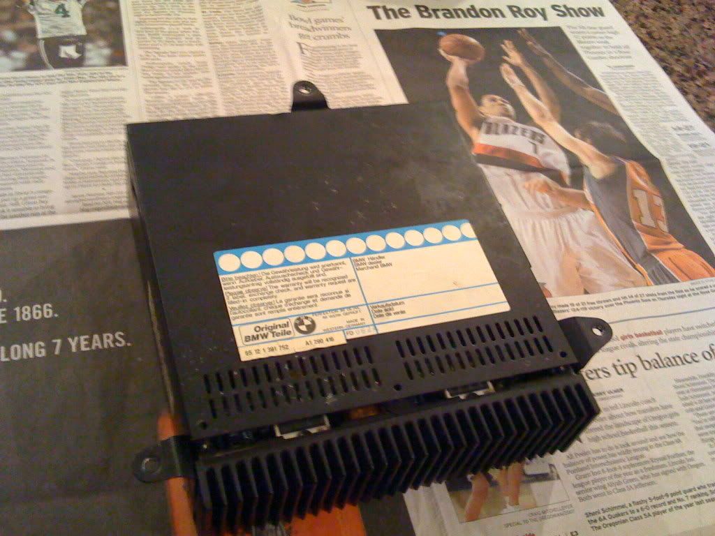
Phase 2: i pulled the actual amplification section off the stock amp and soldered on a set of harnesses I had sitting around in my toolbox for the last 7 years.
I then soldered a reverse set of harnesses to the high level inputs inside the amp (I am using an aftermarket head which has more RMS output than the factory amp ever did). Note the shared negative... I tried NOT running a shared negative and running a seperate set of negatives forthe rear speakers directly from the the head unit and got noise, lots of it, so I reverted to the factory shared negative as seen here.
Note: a sharpie works great for marking the circuit board before soldering... and just might keep you from making a mistake.
That completed I connected the harnesses together and took the gutted amp out to the car and plugged it back in
NOTE: I had messed up the retainer-spacers taking the lower board out of the amp, so I laid a simple sandwich sized ziploc bag on the bottom of the amp shell to prevent any shorts before reassembling the amp. It fits perfectly.
Abracadabra, better sound... and by simply plugging an unmolested amp back into the OEM plug I can RTS.
But that wasn't good enough...
Phase 3:
JPWheeler kindly provided me with an amp with a high level input section to try out, SO I attached another set of matching radio side and reverse harnesses to the highlevel input and to the Output on said amp. These match the set i installed inside the amp in phase 2.
After running a power and ground (harnesses already had a turn on lead incorporated) I took one more listen, and then plugged the external amp in between the highlevel input and the crossover side of the amp...
IN short it made a world of difference... The stock nokias now have enough power to play with authority (perhaps a bit too much authority on the dash " upper mid/ tweet") and the active xover lets me protect the stock midbasses. Overall after a little tweaking, I'm pretty happy for now. At least until I can install a sub, etc.
Best part is I can swap in different amps in a matter of Minutes. And it all tucks away nicely...
Well nicer than this photo would suggest, as I still hadn't rewrapped the OEM harness when I took this pic.
I have decided though that watercooling the PPIs with an externally mounted radiator & fans will definately be the way to go because I can hear the little Next amp's fan running full bore after listening at moderately high to high volumes. And to be honest hearing fans between tracks annoys me.
IT is in the left cubby... behind the insulated wall.
Establishing shot:
Panel open
Here you can see how I moved all the harnesses so I could lay it down in the cubby floor semi permanently. Unfortunately that meant I had to break the mounting tabs off.
hope that helps.
ST: mine has been amped for about 2-3 months now. I have had no difficulties with anything at all. Others before me have amped the system thru the stock crossover section with no problems either.
NO problem...
but lets clarify first...
the average modern day 40-50Wx4 head... is only 15-18w rms x4.
The factory amp, is only about 15-20w x4 peak.
Your speaker level inputs to the amp are not cumulative with it's output.
Any improvement in sound (until the earlier point of distortion) after adding an aftermarket head to the factory amp is strictly from having a better, more dynamic signal to the amp.
my suggestion is to go get a set of harnesses like you would use for a radio... you want a matching radio side and reverse (carside) harness.
Doesn't matter what they are for, just that they have all 8 speaker wires and match each other. It will also give you the same color combo as seen in my pictures.
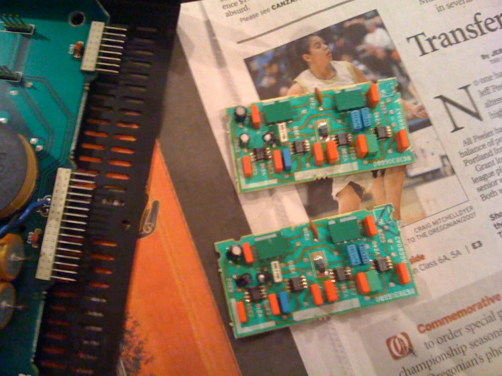
when you pull the old "amp" off the board horizontally (it is just the heat sink part, and it is not reused) you do this... I took my board completely out of the shell and did my soldering on the reverse side.
I put it back in the amp shell once finished. notice in this picture the vertical input board is still not on it.
now you can input a signal directly to the speakers thru the factory xover. This would be your stopping point if you had an amp running off rcas.
For head unit power, or to source a high level input for an amp:
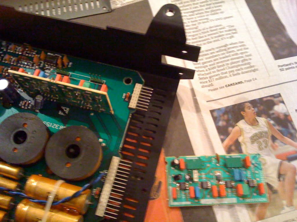
To source the speaker outs from the head unit in a clean way, I simply took my other matching harness, and soldered it on the correct pins inside of the upright input board. I soldered on the pins that matched this plug. note I wrote each one on the back with sharpie first so I wouldn't bollox it.
You can see here that I have almost finished attaching all the wires to the backside of the board, on the opposite side of the plug... thus giving me speaker level signals inside the amp shell... instead of tapping the wires outside of it. (which looks terrible and is hack-ey)
Once you have both of them done, and both pieces reassembled and back in the car (remember you do NOT reuse the 4x15 amplifier board!) connect the plugs for your harnesses together...
Then you are taking the speaker level output of the radio... running it to the rear of the car via factory wiring. This mod loops it inside the reminder of the factory amp directly to the xover input (instead of forcing you to turn down the head and signal low enough that it can amplify what could have been higher powered)
That xover splits it up and sends it back out of the "amp" to the speakers via the factory wiring.
Make a little better sense?
Once you take the cover off the amp and look at the board arrangement, you'll see what I mean
Last edited by attack eagle; 09-19-2012 at 12:16 AM.
Member
This is great info. I'm in the middle of upgrading the audio in my e34 touring as well.
First question - where the heck is the amp located!!
Second - is there any concern that the stock cross-overs will have problems with the increased current you are pumping. Especially with the amp?
Member
It is located on the left side of the trunk.
Member
I see. But where is it in the Touring? I had heard it was behind the CD changer (in the left side compartment), but mine wasn't there. I'm thinking it might be behind the left side panel covering the wheel-well...
License Revoked
erased
Last edited by attack eagle; 09-18-2012 at 11:17 AM.
Member
Found it! There was actually a panel installed that the CD changer mounted to. It was behind the panel. Thanks
Member
Awesome writeup.

Kesslerbmw
This is kinda how I have mine set up.. Im using a dead head unit w/RCA's ran to aftermarket amps in the trunk which are then ran to the Factory Nokia's and it sounds fabulous. With a sub installed its just right. Its by no means a competition stereo but those little Nokia's rock and roll if you give them clean signals.
Member
Well I went ahead and installed new 6 1/2's in the back (Infinity components) and 5 1/4's in the front (Infinity 2-ways). The 6.5's fit fine in the roof, although I did need to drill new holes for the screws and the stock covers no longer fit. I put 6.5 components in the back BUT am powering the tweater in the front door with the provided crossover. I've just left the tweeters in the rear dead. I also installed a 12" sub in a sealed box and have a small 200W amp running just for this. The other speakers are powered from the head unit.
With the sub filling in the bottom end the system now rocks. With the sun roofs open it's a little stretched - so I might get a small 4x50W amp in the future.
Here's the thing - one of my front 5.25's was broken so I left the nokia on one side and upgraded the other. I think the Nokia sounds better!! I must admit that I was chuckling at previous posts saying the Nokias sounded great. Shame on me! I do thik the 6.5's in the rear have better sound - but I'm really impressed with the Nokia's up front. I think I'm going to put the stock one back in the front
E34 Elite Member
so lemme get this straight... My alpine 7894 headunit is not getting its full 30watts rms to each speaker because the stock amp is limiting it to an only (very optimistic)18watts? And by doing this bypass, it allows the alpines 30w rms to power the speakers rather than the stock amp?
I was under the impression that the alpine and stock amp worked together to get a compined power rating of about 48 watts. It seemed right because it only took 8 clicks of the volume knob before the speakers started getting distorted, rather than the 15-20 clicks of my old 15w sony headunit...
Attack Eagle, please show some pictures of the harness you soldered onto the amp and where it connects, im still very confused about this.
1995 BMW 540im/EAT/3.64lsd/M Parallels/Eibach/Koni/Magnaflow & M-tech exhaust
License Revoked
erased
Last edited by attack eagle; 09-18-2012 at 11:18 AM.
Member
BMW CCA Member
Nice write up.
Too bad I just yanked all that crap out and built a new system from scratch.
95 540i6 M Sport - 95 525it S52/OBD2 - 433k E36 328i5 - X5D that hit a pothole - IG: @justinmurray95
E34 Elite Member
Ok, now i can see what you did. Nice write-up. The Alpine headunit i have has a built in amp that produces 27watts RMS and 60watts Peak, its beefy as hell for a headunit.
1995 BMW 540im/EAT/3.64lsd/M Parallels/Eibach/Koni/Magnaflow & M-tech exhaust
MORΩN ΛABIA
BMW CCA Member
So I've got my amp in lots of pieces, and I've been poring over this writeup and its photos for the last hour or so. I'm still confused, but at least I have specific questions now.
The 4 pairs of wires soldered onto the amp board - the grey, white, purple, and green - where do they go? Are they just wires that are supposed to run all the way up to the new headunit's wiring harness, connecting to its speaker leads? If this is the case, then what do I do with the OEM speaker positive leads up front when connecting a new headunit?
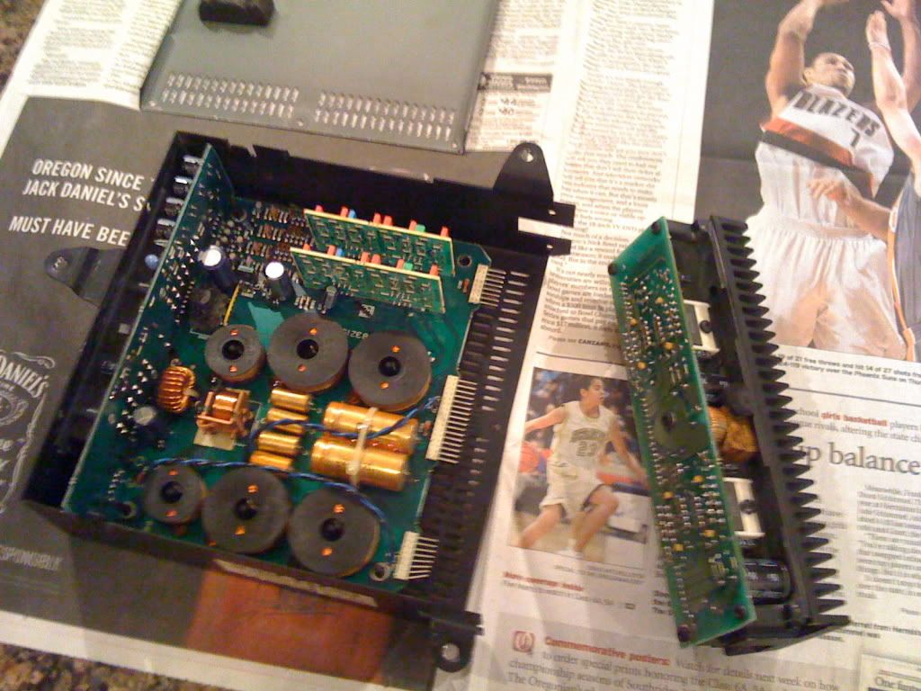
In the third photo, where do the other ends of the wires on the left connect to?
In the photo showing the amp board in its case on top of the sandwich bag, what are those intertwined blue and black wires?
If my new headunit's instructions and tech support both say to not use a common ground, does this writeup still apply? If not, what do I need to do?
My amp looks slightly different from yours - it's missing a few components like the three blue capacitors. Does that matter?
Last edited by moroza; 06-08-2007 at 04:59 PM.
MORΩN ΛABIA
BMW CCA Member
Great...so my car's an oddball among oddballs, in an area of expertise that is by no means mine. Dammit. No, I never had the big plug - I had the little individual ones.Originally Posted by attack eagle

While clueless about car audio, I'm rudimentarily familiar with guitar amps, and one of the first things to learn about those is that they can be fried (as in, smoke and sparks, not just a wispy fuse) if run without a speaker attached. It's not an instant kill, because I've done it accidentally a couple of times, but I can't imagine it'd be good for my shiny new headunit?If they are not common ground for the amp to speakers themselves... My suggestion would be to wire up the aftermarket radio in the trunk temporarily, (with the factory radio unplugged completely!) and see if it works by applying 2 of the 8 wires directly to 2 of the 8 wire locations you would have added to the amp pins.
That would be the first thing I'd try, but judging by your description of the white plug, there's no (easy) getting around the common ground that the E34 has and my new headunit is supposed to be unable to handle. Or is there?...revert to the write up on bmwe34.net for getting the head to work with the factory amp as is...
Speaker level input...from the headunit's speaker output?http://i18.photobucket.com/albums/b1...4AMPbypass.jpg
I'm glad to help Mor.(no pun intended) in the interest of clarity.
these wires would the new speaker level "input" to the passive xover board.
What's up with the blue one? It's not one of the 8 wires soldered to the big amp board. Do these wires connect to the headunit along with the aforementioned 8? And something above about external amplifiers and RCA's? I'm lost...http://i18.photobucket.com/albums/b1...r/100_1137.jpg
Those would be the speaker level outputs from the headunit (92-93).
You can connect them to the wires above to avoid running all new wires from the radio, or if you have an external amp that accepts high level inputs and dont feel like running rcas (yet) they will connect to it.
If you look carefully, the board is upside down compared to the pin out picture directly above it, but the colors/locations correspond to those in the previous picture (#3).E&M and anything related to it has always been a problem for me. Baby steps, please? The extent of my knowledge on car audio is Ohm's law and miscellaneous other bits of electrics, a vague idea of what a crossover is, and that's about it. I much appreciate the assistance, but a lot of it is over my head.
MORΩN ΛABIA
BMW CCA Member
Ok, I played around some with a multimeter and learned a few things. First, the impedance ratings on my speakers are off. The 8-Ohm tweeters are actually 5.9, the 4.5-Ohm mids are 4 or so, and the 4-Ohm woofers are 3.5.
Is the crossover before the amp or after?
Mulling over the writeup and trying to figure out where things go with my amp, it seems that my circuitry is sufficiently different from yours that I can't connect wires in the same places and expect it to work. At the very least, the speaker leads to the big board (this is the crossover in its entirety, and nothing else?) are reversed in places on mine. But with some assumptions, it looks like your method would work for mine, but only if I could figure out the equivalent soldering points. So how'd you determine yours? I don't suppose you found a schematic somewhere?
I assume that what my headunit really wants is for the speakers to be grounded to nothing, and just loop back to the unit via negative leads, though components at each respective corner will share a ground. Does that sound right? If so, it looks like the only other modification I'd need to make to the crossover is disconnecting its shared chassis grounds (at the white plug), which is ok since the 8 wires running to and from the headunit would take care of grounding. This is just starting to make sense to me, so please let me know if it sounds right.
Last edited by moroza; 06-09-2007 at 09:05 PM.
License Revoked
I think your last paragraph is about what I was thinking.
Be aware, when you look at my picture of the big board (passive xover only) you are looking at the REVERSE side. NOt the side with all the parts on it that is facing you normally.
MORΩN ΛABIA
BMW CCA Member
Yes, I'm aware of that. Mine is definitely different from yours. Can you tell me how you figured out what goes where on yours, so I can do the same to mine?
On a side note - do I have to worry about impedances when doing this? I know that the front corners are going to be different from the rears no matter how they're all arranged. Will that cause a volume imbalance, or hurt the headunit, or cause some other problems?
License Revoked
I found a picture thread about doing the passive xover mod... I jsut took it one step further in figuring out how to loop it to head unit power
MORΩN ΛABIA
BMW CCA Member
Ok, I've figured out how to do this writeup with my current system. I drew a schematic and it's all pretty and symmetrical, and everything would be kosher if not for the last question - I've got 1.7 ohms (nominal) on each front channel. I don't fully understand how inductors and capacitors affect this, so this measurement is done the "stupid" way - assuming a direct current.
The instructions for the headunit say that its operating range is 4-8 ohms. I assume that's nominal, and with no filters. Can I still hook up my HU the way you did, and have it work? I can't imagine yours has a drastically different operating range, and yours worked fine when directly powering the speakers (same speakers I have)?
License Revoked
like you said mine worked fine...I didn't even bother to measure the impedance... I'll do it next time I have the backseat off ( the factory amp rememnant is under there now).
MORΩN ΛABIA
BMW CCA Member
JVC tech people say it'll run 1.7 but might overheat. I interpret that as a green light, so I'm good to go. Now to run all those damn wires. Or rather, fix my AC so I can actually be inside the car for any of this. Thanks much for your help!
Member
revival of old thread FTW!
but really, i've got a few questions... and pics
first off, i have a 1990 535i, which means i have a common ground system... riiiight? well that's what i thought too... i FINALLY got around to removing my amp and dismantling it a little bit, and i have realized that it appears to be the exact same amp as yours, attack eagle.
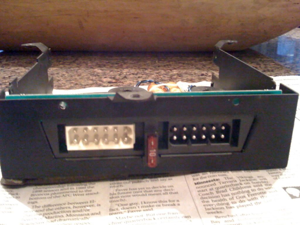
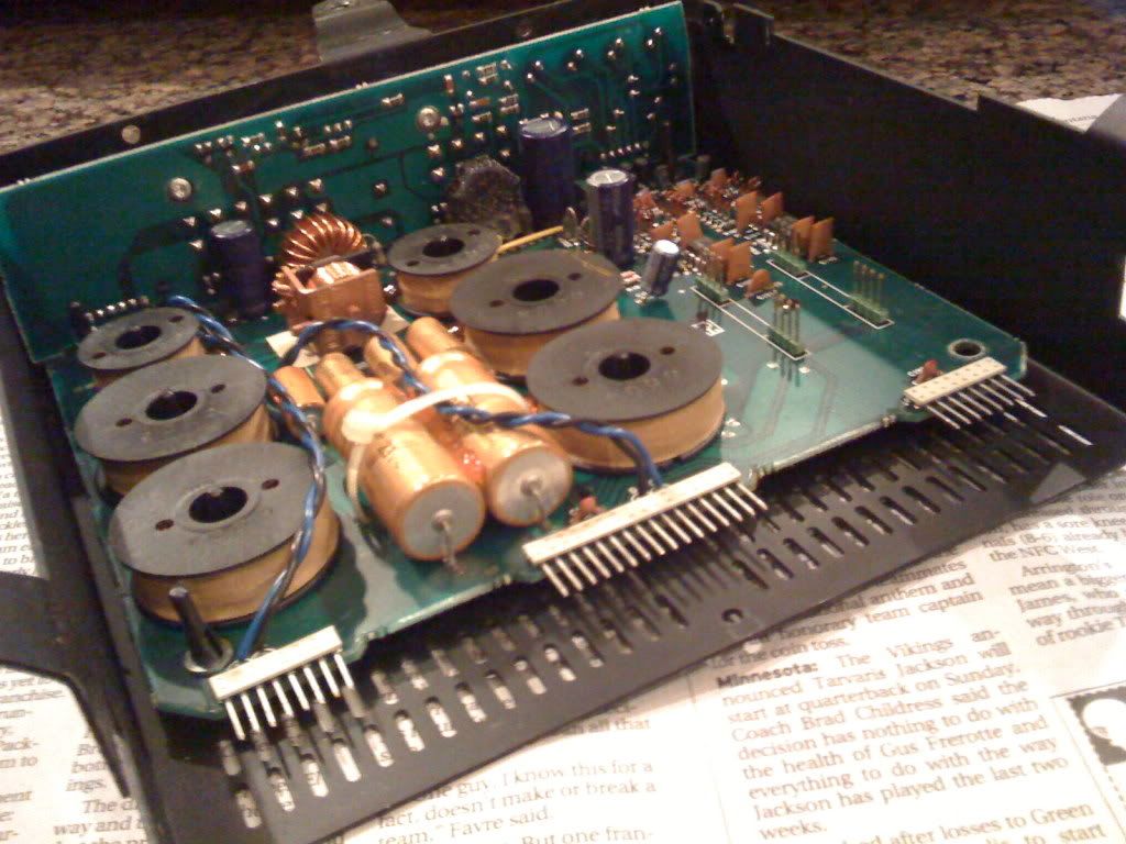
amp
rear
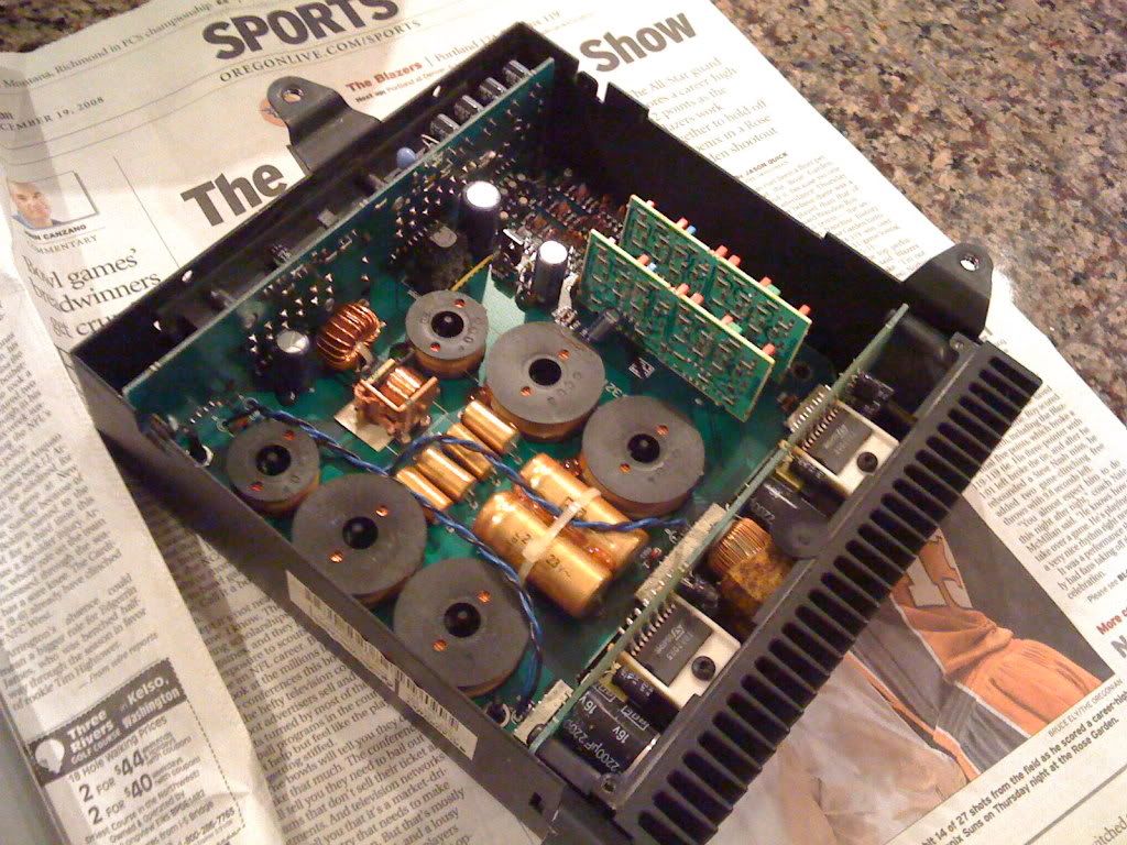
open
question: is the amp on the right with the heatsink, and the crossover everything else?
what are these little guys mounted onto the main board?
i haven't removed the board completely from the casing, but it appears to be exactly like yours attack eagle..
what do you guys think?
my goal is to run an aftermarket HU to an aftermarket amp via rca, through the stock crossover to the speakers.. can this be done with this crossover?
License Revoked
yes, the common ground amps look very much like the 91-93 amps.
that is definately a common ground amp... i don;t have those extra circuit boards you were talking about.
What you are talking about doing with an external amp sounds excellent.
Last edited by attack eagle; 12-19-2008 at 08:28 PM.
Rotary engine goes hmmmmm
I'd love to do this to my car. Subscribed.
 Posting Permissions


")
Bookmarks