
 Member
Hi!
In my car doesn't work driver lock and mirrors heating. This missing relay can cause this issues? Which relay should be there?
I've took a few photos but i can't post it here :/
Thanks for your help!
Member
theres no such thing as a 95 328.
Member
There is when you get outside the US.Originally Posted by BMW325issport

OP your windows and locks are controlled by the ZKE module. Behind the glovebox is a stack of control modules. the one on top will have 3 different colored connectors. That's the ZKE module. Your heated mirrors dont use a relay. I can't remember if they are wired through the ZKE module or not.
The control modules in these cars are pretty robust and its fairly rare for them to go bad. I would look for another cause before you spend money on a new/used module. Check all your fuses first. If you have a test meter then pull each one out and test it even if it looks good.
You can also post the symptoms you're having and we can try to help you fix it.
Bleed your cooling system http://forums.bimmerforums.com/forum....php?t=1709482The ULTIMATE OEM Alarm/Keyless thread http://forums.bimmerforums.com/forum....php?t=1792200
shade tree mechanic
Moderator
mirror heating must be different from ZKE, it is not mentioned in the function description of the ZKE IV.
here is the complete system explained, central locking - ZKE IV
http://www.unofficialbmw.com/images/lock.pdf
Central Locking
Purpose of the System
The Central Locking System provides locking/unlocking of the entire vehicle from one central exterior point. From the drivers door, passengers door or luggage compartment (>96 MY), a lock/unlock request will lock/unlock all exterior doors, luggage compartment and the fuel filler flap (and glove box E36iC only).
Locking from the luggage compartment lock cylinder and leaving the lock cylinder in the horizontal position will manually lock the luggage compartment in the valet position.
From inside, the vehicle can be locked using one of the front door lock knobs or a central locking button (>96 MY E36 which also unlocks the vehicle) located in the center console.
The doors can be unlocked by pulling twice on the interior door handle.
Locking the vehicle from the central switch or door lock knob
will single lock all doors, luggage compartment and not lock the fuel filler flap (or glovebox on the E36iC). The Central Locking System utilizes the GM IV to carry out all of the locking/unlocking features:
When locked from the outside, the vehicle will double lock and arm the alarm system (only if equipped with DWA, not the accessory Alpine Alarm). The ignition must be switched
off and the drivers door must be opened and closed.
The EWS II is interfaced for double lock monitoring and unlock function(>1/95 Production Date). With the presence of an accepted EWS II key and switching the ignition on, the
GM IV will unlock the vehicle.
In the event of an accident (ignition must be switched on), the GM IV will be signalled to unlock all of the doors.
Anti-theft drive away protection feature with double lock (>1/95 Production Date when locking the vehicle from the exterior).
Comfort closing of the windows is posible from both front door locks if held in the lock position.
1996 E36 - Sunroof added to comfort closing feature.
E36iC - The trunk is locked out when the convertible top is in operation. Fully automatic convertible top added to comfort closing feature (97 MY and later vehicles).
Hardware Features
The door lock buttons are mechanically uncoupled from the lock actuators when locked. The door lock buttons also mechanically lock the individual doors. This provides manual
locking in the event of a central locking malfunction.
Child safety locks (located in the rear doors on a four door vehicle) are actuated by sliding a lever. The door can now only be opened from outside.
The luggage compartment can be manually locked with a Master Key and leaving the lock cylinder in the horizonta position which prevents opening by any other method (secured
for valet).
The Fuel Filler Flap mechanical release is found in the right side of the luggage compartment.
The glove box has a lock cylinder to secure the contents by manual locking with a Master Key and leaving the lock cylinder in the horizontal position which prevents opening by
any other method (secured for valet).
The valet key is not mechanically capable of entering either of these lock cylinders.
The locking and unlocking of the lock actuators is controlled from three relays in the GM. The door lock actuator Pin Contacts and lock micro-switches provide the inputs to the
GM for locking/double locking and unlocking of the doors, trunk, fuel filler flap (and glove box on the E36iC only). The relays in the GM provide both power and ground depending
on the direction of actuator movement (lock/unlock).
Lock Actuator Operation
The lock actuators contain the electrical motor drive, the lock/unlock switch contacts and the integral single/double lock limiting switch.
The actuators control the mechanical locking/unlocking function of the doors by sliding two protruding levers. The precise ositioning of the levers provides the unlock, single lock and
double lock positions of the latch mechanism. The electro-mechanical operation of all the lock positions are provided on the following pages:
UNLOCKED-NEUTRAL POSITION
All switch contacts are in their rest positions.
The lock actuator/latch mechanisms are in the unlocked position.
Raising the door handle or pulling the interior door latch will mechanically open the door.
Central Locking System Terminology
Single lock, Central lock: Vehicle is locked via the lock knob, or the console mounted central lock button (>12-95 prod).
Double lock, Central arrest: Vehicle has been locked from the exterior with the key at the drivers door, passengers door or trunk.
SINGLE LOCK - Phase 1, mechanical lock at door and lock signal generation
The lock button and key mechanically rotate the lock lever which decouples the exterior door handle from the latch.
When rotated, the lock lever also slides an internal switch ramp to the left closing the lock microswitch.
This provides the lock signal to the GM
SINGLE LOCK - Phase 2, activation of actuators at all door locks
When the GM receives the lock signal it activates internal relay #1, providing power through the closed single lock contact to the actuator motor. Ground is provided through the modules
closed contact of relay #3.
All of the vehicles actuator motors are energized until the single lock circuit is opened by the gear driven slider. The actuators stop at the single locked position.
At this point, the external door handles are decoupled from the latch mechanism preventing entry from outside of the vehicle.
If the internal door handle, the lock buttons or the central lock button on the center console are operated, the door returns to unlock mechanically and can be opened.
DOUBLE LOCK - Electrical Activation
Turning the key from any outside lock cylinder causes the external double lock micro-switch to close. The GM recognizes this high signal as a double lock request.
The GM activates internal relay #2, providing continued motor operating power through the closed contacts of the internal double lock circuit. Ground is provided through the GMs
internal relay # 3. The actuator motors are energized until the internal double lock circuit is switched back to the single lock circuit by the gear driven slider.
DOUBLE LOCK - Mechanically Decoupled
When the slider switches the circuit back to single lock it also pushes the double lock lever to the left until it stops. In this position, the double lock lever decouples the lock button from
the latch mechanism. The lock button can be pulled but will not unlock the door since it is not coupled to the mechanism. Spring pressure pulls the button back down when released.
At this point, unlock is only possible when a key is turned to the unlock position from an outside door lock or if the GM receives the unlock signal from the EWS II control module.
UNLOCK FROM DOUBLE LOCK
When the GM receives the unlock request from a key location it activates internal relay #3 providing operating power to the actuator motor in the opposite direction.
The single and double lock circuits (internal relays 1 & 2) are not activated at all during the unlock function providing ground for the motor to bring the actuator back to the fully unlocked
position.
Locking Protection
Power protection for the door locking circuit is provided by a time monitored activation of the door lock actuators by the GM. The door lock actuators are provided power for the
duration of time needed to run the actuator to the desired position.
The maximum on time for the actuators is 0.7 seconds.
Crash Signalling
The Supplemental Restraint System control module provides a switched signal to the GM in the event of an accident. This signal was previously provided by the Crash Alarm located
in the left front kick panel on earlier models (<97 MY).
The signal is an output function of the control module and becomes active when the impact threshold has been exceeded. The GM unlocks the vehicle, switches on the interior lights
and signals the Crash Alarm Relay to flash the exterior lights when this signal is active.
Door Lock Heating (optional)
Purpose of the System
The Drivers door lock cylinder is surrounded by a heating coil to warm the lock cylinder if in case it is frozen due to moisture and below freezing temperatures.
Principle of Operation
The GM controls the lock heater by providing voltage through a final stage transistor. The heater is switched on by raising the drivers door handle. Prerequisites for heater operation
include:
Vehicle locked
Door handle raised for approximately 3 seconds
Power is applied to the heater for a maximum of 32 seconds. A timed arrest of 16 minutes is activated after 3 heating attempts. The door lock heater is switched off immediately after unlocking the door.
Shogun tricks and tips for the E32 series are HERE!
Member
Thank you guys for your replies!
Yes, you're right. But on the left you have a 'distribution box' (I'm not sure if it's a proper word) with relays...
And what about driver lock heating? Or this is the same wiring?
All fuses are ok. In the cold mornings mirrors are always steamy. I've also checked wires behind mirrors, it looked alright. What's wrong?
Can anyone send me an email (ppiotrek90 at gmail.com)? I will show you this photo with missing relays.
Member
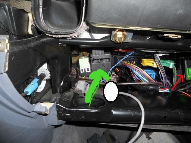
The green arrow points to a large box with lots of wires. This is a splice panel. Its used to tap into the factory wire harness without cutting/splicing any wires. There aren't any relays that go in that box. Just to the right of that box/arrow you can see the three colored connectors that plug into the ZKE module. Just to the left of that box is a relay. Your car may or may not have that relay. You may have more than one there. Im not 100% sure what its for. I never had to find out.
The heated mirrors and door lock don't use a relay. You may not even have heated door lock or mirrors. To find out if you have heated drivers door lock take the door panel off and look at the outside door handle. The wire harness in the door will have 3 connectors going to it. Yellow, Gray, White. The yellow one will be plugged into a corresponding connector on the door handle. That yellow one is for the micro switch that gets triggered when you turn the key in the lock. If the gray one is plugged into a gray connector then that one is for the micro switch that turns on the interior lights when the door is locked and you lift the handle. If the white one is plugged into a connector that is for the lock heater. Its activated only if the door is locked. Lift the handle and it turns on the heater for a max of 1 minute. Its not a super powerful heater.
As far as I know the heated mirrors come on as soon as you turn the key. According to the wire diagram there is no thermostat of any kind that controls them so they will actually come on when its above freezing. If you have wires that plug into the glass plate on the mirror then the heater is probably bad. You can test it with a meter. If you get any voltage to those wires then you need to replace the glass. I got replacements on ebay for under $25. Make sure you get glass for your body style. Sedan mirrors are different from coupe mirrors.
Last edited by flyfishvt; 11-25-2012 at 05:14 PM.
Bleed your cooling system http://forums.bimmerforums.com/forum....php?t=1709482The ULTIMATE OEM Alarm/Keyless thread http://forums.bimmerforums.com/forum....php?t=1792200
Member
I went through diagrams and it looks like that this is horn relay! Maybe this is the reason for my faults below.
13 hood/radio - sensoring hood-/radio-contact
5 alarm horn output (relaisbox)
 Posting Permissions


 Reply With Quote
Bookmarks